Publisher’s version / Version de l'éditeur:
International Journal of Road Materials and Pavement Design, 2, 2, pp. 205-216,
2001-08-01
READ THESE TERMS AND CONDITIONS CAREFULLY BEFORE USING THIS WEBSITE. https://nrc-publications.canada.ca/eng/copyright
Vous avez des questions? Nous pouvons vous aider. Pour communiquer directement avec un auteur, consultez la première page de la revue dans laquelle son article a été publié afin de trouver ses coordonnées. Si vous n’arrivez pas à les repérer, communiquez avec nous à PublicationsArchive-ArchivesPublications@nrc-cnrc.gc.ca.
Questions? Contact the NRC Publications Archive team at
PublicationsArchive-ArchivesPublications@nrc-cnrc.gc.ca. If you wish to email the authors directly, please see the first page of the publication for their contact information.
NRC Publications Archive
Archives des publications du CNRC
This publication could be one of several versions: author’s original, accepted manuscript or the publisher’s version. / La version de cette publication peut être l’une des suivantes : la version prépublication de l’auteur, la version acceptée du manuscrit ou la version de l’éditeur.
Access and use of this website and the material on it are subject to the Terms and Conditions set forth at
A New way to mitigate frost heave around manholes
Svec, O. J.
https://publications-cnrc.canada.ca/fra/droits
L’accès à ce site Web et l’utilisation de son contenu sont assujettis aux conditions présentées dans le site LISEZ CES CONDITIONS ATTENTIVEMENT AVANT D’UTILISER CE SITE WEB.
NRC Publications Record / Notice d'Archives des publications de CNRC:
https://nrc-publications.canada.ca/eng/view/object/?id=5fd70a81-446f-4a40-ad41-ada71e27710e https://publications-cnrc.canada.ca/fra/voir/objet/?id=5fd70a81-446f-4a40-ad41-ada71e27710e
Svec, O.J.
A version of this paper is published in / Une version de ce document se trouve dans : Road Materials and Pavement Design, v. 2, no. 2, 2001, pp. 205-216
www.nrc.ca/irc/ircpubs
A new way to mitigation frost heave around
manholes
O.J. Svec
Senior Research Officer
Institute for Research in Construction National Research Council Canada Montreal Rd, Ottawa, Ontario,Canada K1A 0R6, otto.svec@NRC.CA
ABSTRACT: Frost heave of pavement around manholes in northern cities all over the world has been a costly problem ever since sanitary and storm sewers were installed. Freezing of frost-susceptible soil under the road structure can lead to substantial uplift, deformation and cracking of the pavement surface. This new technology is based on utilizing the heat in flowing water in sanitary and storm sewers, as well as the existing heat in the soil located deep around the manholes. Inside the manhole during winter, the air temperature is cold at the top and warm at the bottom generating air convection. The warm air flows from the bottom to the top of the manhole where it cools; this cold air then flows down to the bottom of the manhole where it warms up again. The heat energy in manholes with a perforated steel cover is simply lost. The innovation described calls for a closed system, where the heat energy is transferred to the area under the pavement structure, thus preventing the 0ºC isotherm from reaching the frost-susceptible soil below.
In collaboration with the City of Nepean, part of Greater Ottawa, Ontario four manholes were reconstructed using the new frost-heave mitigation principle. A third manhole was instrumented as a control. The author, who is also the applicant for a patent on this new technology, provided the design for the reconstruction. The results of the trials during the winter of 1998-99 demonstrated that the innovation “works,” as the frost did not reached the frost susceptible soil (Leda clay) surrounding the manhole and did not cause any pavement deformation.
1. Problem
Deformation and cracking of asphalt pavements around sanitary and storm sewers are major and costly problems for many municipality in Canada and the northern United States, except those on the West Coast. This is also true for cities in most of the northern countries . The major cause of this pavement deterioration is frost heave. Frost heave of soil can lead to a substantial uplift (5 to 10 cm) as well as cracking of the pavement surface around manholes (see Photographs 1 and 2). For frost heave to occur, three conditions must exist: a) sub-zero temperature, b) availability of water and c) frost-susceptible soil. If one of these factors is removed, the frost heave will not occur. This paper describes an innovative process to prevent frost heaving and pavement deterioration around manholes. The concept of this
innovation is based on removal of the first factor, i.e., on stopping freezing temperature, from moving below the pavement structure down to frost susceptible soil.
Photograph 1. 5-cm frost heave and pavement damage around a manhole.
A tremendous amount of field and laboratory research has been performed over the last 70 years to understand the freezing process. Although the process of frost heave, i.e., of soil segregation (ice lensing) is now reasonably well understood, alleviation of this problem has been difficult. Many attempts to develop realistic numerical models leading to frost heave prediction have not borne fruitful results. Therefore, reasonable numerical and analytical solutions resulting in quantitative determination and engineering prediction of this phenomenon are not yet at hand.
Tile of Journal. Volume X – No. X/19993
Photograph 2. Cracking of the reconstructed pavement around a manhole.
The mitigation of frost heave and consequently the alleviation of cracking of the asphalt pavement around manholes has never been solved. The only method, that has so far been used, is the placement of high-density polystyrene insulation under or in the pavement structure. However, that has led occasionally to even more dangerous problems particularly in the autumn. At sub-zero temperatures in the autumn the pavement does not freeze, because there is enough heat in the ground moving up to the pavement surface. The insulation in the road structure stops this heat from flowing and thus allows the pavement to cool and freeze. Therefore, at the interface between the non-insulated (unfrozen) and insulated (frozen) road sections this caused vehicles to skid. The same situation would occur if the road around the manholes were insulated; it would create many such interfaces between frozen and unfrozen pavement.
Considering the number of manholes in countries with frost heave problem, a huge amount of money could be saved through a considerable reduction in the frequency of pavement repairs around manholes. The author believes that a new patented invention described below can solve this problem completely or, in very cold regions, partially
.
2. Concept Basic to the Innovation
As described above, one of the ways to stop frost heave of pavements is to prevent the 0ºC isotherm from moving down into the soil below the road structure. To do this, which is also the basic feature of this innovation, the existing heat in a manhole must be transferred under or into the road structure. This heat creates an energy barrier preventing the downward movement of the 0ºC isotherm. For this purpose, the heat from flowing water in sewers; i.e., sanitary and storm, as well as the heat from the soil located deep around the manholes is used. The key to this innovation is the use of the natural air convection caused by the difference in temperature boundary conditions in an enclosure:
Inside a manhole during winter, the air temperature is usually cold at the top and warm at the bottom. For example, the air temperature at the top (just below the steel manhole cover) inside the manhole might be -10°C, while at the bottom, it might be +10°C. Such a temperature difference generates air convection because of differences in air density and gravity inside the manhole. The warm air flows from the bottom to the top of the manhole where it cools, and then this cooled air flows back down to the bottom of the manhole where it warms up again. Normally, the heat energy in manholes with a perforated steel cover, such as storm sewers, is simply lost without being of any beneficial use. The innovation described calls for a closed system, where the heat is transferred to the area under the pavement structure, thus preventing the 0ºC isotherm from reaching the frost-susceptible soil below.
Tile of Journal. Volume X – No. X/19995
Figure 1. Concept of mitigation of frost heave of pavement around manholes.
This can be achieved by modifying one of the manhole rings, i.e., by introducing vertical slots in it (see Figure 1 and Photograph 1). If such a modified ring is placed at the upper part of the manhole, warm air can flow through the holes into a special aggregate layer, located under the pavement structure (see Figure 1). As a result, the 0ºC isotherm stays in the pavement layers and does not move into the frost-susceptible soil below, where it would cause frost heave. To enhance this action, a large-stone (i.e., 51mm), clean aggregate layer with a high air void-ratio replaces the subbase or a soil layer around the modified manhole. During reconstruction, a geotextile blanket is placed under, around and on top of this special aggregate layer, thus creating a “radiator bag.” The heat in this bag (which is circulating from inside the manhole) stops the frost from reaching the frost-susceptible soil, such as clay or silt, below. In addition, polystyrene insulation is prepared in the form of two half-circular plates and placed on the internal edge of the top manhole ring to stop the heat from escaping to the atmosphere (see Figure 1).
3. Construction of Field Tests
In collaboration with the City of Nepean two manholes were reconstructed using this new frost-heave mitigation principle (see Figure 1). The author, also the applicant for the patent, provided the design for the reconstruction. The process of reconstruction was as follows:
1) Two meters of the pavement and soil were first removed from around the manhole, thus creating a circular hole 5 m in diameter. The depth of excavation was about 1 m.
Photograph 3. A new modified manhole ring with eight vertical slots.
2) During excavation, the existing rings of the manholes were removed to approximately the same depth, 1 m. In order to obtain the proper level for placing the ring with slots (modified ring), another new (standard) ring was placed on the remaining manhole as a spacer.
3) On top of that, a new modified ring with eight vertical slots [2 in. (51 mm) wide and 10 in. (254 mm) high] was placed and properly cemented (see Photograph 3).
4) Around this specially manufactured modified concrete ring, galvanized steel mesh was placed (see Photograph 4), to prevent small stone chips from falling into the manhole. This photograph also shows the placement of thermocouple cables and the box for the data logger.
Photograph 4. Modified manhole ring with galvanized mesh around it and the geotextile and clean large aggregates creating the “bag – natural radiator.”
5) The bottom and sides of the excavation (around the concrete manhole) were then covered with a geotextile blanket and filled with clean 2 in. (51 mm) stone aggregate (see Photograph 4) to constitute a layer about 16 in (408 mm) thick.
6) The top of this 16 in. (408 mm) thick layer was then covered with another sheet of geotextile, creating a complete “bag” (a natural radiator) full of clean, well compacted stone aggregates (see Photograph 4). This special layer allows movement
Tile of Journal. Volume X – No. X/19997
of warm air through the large, connected air voids. The air circulation transfers heat from inside the manhole to the “bag” and back.
7) Next in the reconstruction process, the regular ring (without holes) was placed on top of the new one with vertical openings.
8) The subbase was then created by placing crushed stone aggregate over the geotextile “bag” and properly compacting it.
9) On top of that, a regular stone base and asphalt pavement, using two separate layers, were placed and compacted.
During the reconstruction, four cables with 12 thermocouples (i.e., sensors for measuring the temperature with an accuracy of ±0.25°C) in each cable were placed in all key locations. All cables were connected to data loggers, which recorded data automatically at 0.00 a.m., 8.00 a.m. and 4.00 p.m. daily. Periodically, usually once a month, the data were collected in the field and processed in the laboratory.
4. Results
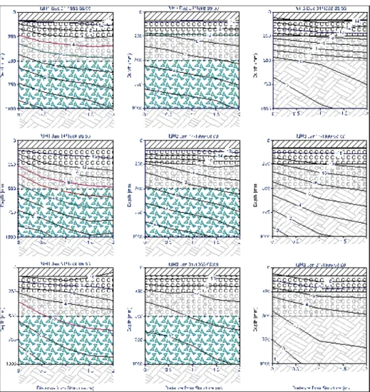
Results described below and shown only in graphical form are based on data taken three times per day between Dec. 24, 1988 and March 10, 1999. For a clear understanding of subsequent figures, a general cross-section including the manhole and temperature profile around the manhole 1 (MH1 – on sanitary sewer) on Feb. 25 is shown in Figure 2. All selected and compressed results describe temperature profiles only. Presented results are from selected dates only more or less at the coldest temperatures. Because all the results indicate that the coldest temperatures occurred early in the morning, graphs (for reason of simplicity) contain only data taken at 8 a.m.
Figure 3 consists of six sets of three graphs, based on results from modified MH1 and MH2 (on storm sewer) and from standard MH3 (on same storm sewer as MH2). Each graph depicts the temperature profile in a vertical cross-section beside the manhole shown in Figure 2. This represents a side section of a “donut” with an outside radius of 2.5 m, the hole radius of 0.5 m and the overall thickness of 1 m. The cross-sectional geometry can be seen on Figure 2.
The following 16 figures show the temperature profiles around the manholes; and show the movement of the 0°C isotherm through the road structure, including the soil below and beside MH3. The first frost under the asphalt layer (90 mm) occurred on Dec. 14, 1998. The 0°C isotherm reached the bottom of the road base (at 250-mm depth) on Dec. 20. On Dec 24. 1998, the 0°C isotherm around all the manholes was at a depth about 400 to 500 mm, i.e., the top of the “bag” (MH1 and MH2) and the bottom of the
Figure 2. Cross-section of the manhole, road structure and the “bag natural radiator”.
sub-base (at 500 mm depth) on Dec. 27. On Dec. 31, 1998 (see Figure 3), the 0°C isotherm around MH1 was slightly inside at the top of the “bag.” Around MH2, it was still above the “bag,” while around MH3 (see third graph), it was already in the soil below the road structure (i.e., 500 to 700 mm depth). The following three graphs demonstrate the position of the 0°C isotherm in the road structure on Jan. 14, 1999 at 8.00 a.m. The 0°C isotherm around the MH1 almost reached the bottom of the “bag,” while around MH2, it remained in the upper half of the “bag.” However, around MH3, the 0°C isotherm had moved into the soil far below the 1-m level (from the surface of the pavement). In fact, the 0°C isotherm is hardly visible in Figure 3 (MH3).
It is important to note that MH2 and MH3 are connected to the same storm sewer. Because an unidentified local industry was dumping warm water into this particular sewer, all temperature results from both MH2 & MH3 were higher than those from MH1. Consequently, the 0°C isotherm around MN3 was considerably higher than it would be otherwise. This indicates that the new frost mitigation system performs even better than measured.
Tile of Journal. Volume X – No. X/19999
Figure 3. Temperature profiles around all three manholes from Dec. 24, 1998 to Jan. 31, 1999 at 8 am.
All the other results (for February and March) demonstrated the same performance throughout the winter 98/99. The movement of the 0°C isotherm was as follows: in MH1 it touched the bottom of the bag 1.5 m away from the manhole, in MH2 it stayed at the top of the bag and in MH3 the 0°C the isotherm moved deep into the soil below. It should be noted that in all figures the interface between the road structure and soil around MH3 is only 500 mm below the pavement surface. Therefore, the frost during the winter was deep in the soil and free to create ice lenses. This certainly proves that this new concept for mitigation of frost heave around manholes works as expected.
Figure 4 shows the freezing process, plotted vs. time, around all three manholes. It can be seen that even at a depth of 0.5 m the effect of the heat from the warm wastewater, which was dumped into the storm sewer, is noticeable. MH2 and MH3 are connected to this storm sewer. It can be seen on the graph for MH2 how significantly
Figure 4. Freezing process around all three manholes in 0.5 and 1.0 m depths at 8:00
AM and at 0.0, 1.0, and 2.0 m distance from manholes
higher the temperature is compared to that around MH1. Furthermore, it can also be seen how large the difference in temperature is between MH2 and MH3. Without the dump of the warm water into the storm sewer, the temperature around MH2 would be similar to that around MH1. Without the warm water, which affects MH3, as well as MH2, the freezing temperature around MH3 would be significantly deeper than that shown in Figure 4. There is clearly no other reason, except the efficient cycling of warm air from the bottom of the manhole to the “radiator bag,” why the temperatures around MH2 are higher than around MH1. (The hotter air from MH2 (when compared to MH1) was also detected during construction.)
The temperature distribution at 1 m depth is shown also in Figure 4. Considering the above, the temperature distribution around MH2 should be similar to that around MH1 (i.e., somewhat colder) and significantly colder (several degrees from January
MH1-Temperature (08:00 am) @ 0.5 m depth -10 -8 -6 -4 -2 0 2 4 6 8 10 12 T em pe ra tu re , °C MH2 - Temperature (08:00 am) @ 0.5 m depth MH3 - Temperature (08:00 am) @ 0.5 m depth 0 m Dist. 1m Dist. 2 m Dist. MH1-Temperature (08:00 am) @ 1 m depth -10 -8 -6 -4 -2 0 2 4 6 8 10 12
Dec-98 Jan-99 Feb-99 Mar-99 Time, Months T e m p e ra tu re , °C -MH2 - Temperature (08:00 am) @ 1m depth
Dec-98 Jan-99 Feb-99 Mar-99 Time, Months
MH3 - Temperature (08:00 am) @ 1 m depth
Dec-98 Jan-99 Feb-99 Mar-99
Time, Months
0 m Dist. 1m Dist. 2 m Dist.
Tile of Journal. Volume X – No. X/199911
on) around MH3. Even so, the temperature around MH3 in January and March was considerably lower than around MH1 and MH2, thus proving the validity of this concept.
5. Conclusion
These results clearly demonstrate that this frost mitigation method is effective. The following important facts were generated from this project:
Observations of the test sites from December 1998 until present (2001) show that the surface of the asphalt pavement around the modified manholes has not deformed, i.e. no uplift from frost heave has occurred.
Because of the lack of deformation or uplift, no cracks have developed in the pavement and, as well, no cracks (space) appeared between the manhole top steel ring and the asphalt pavement occurred.
Based on these observations one can conclude that the possible problem of water infiltration into the manhole through the vertical holes in the modified ring will not occur, simply because there are no “openings” (cracks) in the asphalt pavement for water to flow into. This can be recognized as an additional advantage of this technology.
Water infiltration is usually caused by an open space (due to cracks in the asphalt) between the pavement and the manhole top steel ring. This space normally increases in size every winter as a result of frost heave (uplift) of asphalt and the crumbling effect of dynamic traffic loads. This problem will not occur when the innovation is used. In order to make this system even “safer” from the standpoint of water infiltration, we are suggesting that a hot sealant (or rubber ring) be applied around the top steel ring, before the final hot asphalt layer is placed. This will completely seal the asphalt/steel ring interface.
Another small but very important change in the design of the modified ring will be the geometry of the holes. For better structural strength and for avoiding stress concentration in sharp corners in vertical rectangular holes, the shape of the holes will be either a vertical “rectangle” with rounded top and bottom, or a vertical “ellipse.” In addition, the bottom of the holes will be slanted down in an outward direction, so that any water (condensed moisture in the “bag-natural radiator”) around the manhole will not flow into the manhole. Again, this new design will be tested in the upcoming project.
In general, the results show that this new method is effective, i.e., capable of preventing frost penetration and therefore mitigating frost heave of the pavement around manholes. Clearly, this new system performed its function well. It could therefore, be considered for new road construction, reconstruction and, slightly modified, for rehabilitation.
Acknowledgment
The author wishes to express his deep gratitude to the staff of the Public Works Department of the City of Nepean, Ontario, Canada, in particular to Mr. Wayne Newell, General manager, for their receptiveness to innovative ideas and their support in kind. As well, the author wishes to thank his own colleagues Dr. Don Taylor, Mr. Neil Wakil, Mr. Ted Hoogeveen and Mr. Rock Glazer.