HAL Id: hal-01680649
https://hal.uca.fr/hal-01680649
Submitted on 6 Mar 2018
HAL is a multi-disciplinary open access
archive for the deposit and dissemination of
sci-entific research documents, whether they are
pub-lished or not. The documents may come from
teaching and research institutions in France or
abroad, or from public or private research centers.
L’archive ouverte pluridisciplinaire HAL, est
destinée au dépôt et à la diffusion de documents
scientifiques de niveau recherche, publiés ou non,
émanant des établissements d’enseignement et de
recherche français ou étrangers, des laboratoires
publics ou privés.
Tactile sensing in dexterous robot hands - Review
Zhanat Kappassov, Juan Antonio Corrales Ramon, Véronique Perdereau
To cite this version:
Zhanat Kappassov, Juan Antonio Corrales Ramon, Véronique Perdereau. Tactile sensing in dexterous
robot hands - Review. Robotics and Autonomous Systems, Elsevier, 2015, 74, Part A, pp.195-220.
�10.1016/j.robot.2015.07.015�. �hal-01680649�
Tactile sensing in dexterous robot hands – review
Zhanat Kappassova,∗, Juan-Antonio Corralesb, Véronique Perdereaua
aInstitute of Intelligent Systems and Robotics, University of Pierre and Marie Curie, CC 173 - 4 Place Jussieu 75005, Paris, France bInstitut Francais de Mecanique Avancee, Campus de Clermont-Ferrand les Cezeaux BP265 63175 AUBIERE Cedex, France
Abstract
Tactile sensing is an essential element of autonomous dexterous robot hand manipulation. It provides information about forces of interaction and surface properties at points of contact between the robot fingers and the objects. Recent advancements in robot tactile sensing led to development of many computational techniques that exploit this important sensory channel. This paper reviews current state-of-the-art of manipulation and grasping applications that involve artificial sense of touch and discusses pros and cons of each technique. The main issues of artificial tactile sensing are addressed. General requirements of a tactile sensor are briefly discussed and the main transduction technologies are analyzed. Twenty eight various tactile sensors, each integrated into a robot hand, are classified in accordance with their transduction types and applications. Previously issued reviews are focused on hardware part of tactile sensors, whereas we present an overview of algorithms and tactile feedback-based control systems that exploit signals from the sensors. The applications of these algorithms include grasp stability estimation, tactile object recognition, tactile servoing and force control. Drawing from advancements in tactile sensing technology and taking into consideration its drawbacks, this paper outlines possible new directions of research in dexterous manipulation.
Keywords: Tactile sensing, tactile sensors, robot hands, dexterous manipulation, tactile sensing application, review 1. Introduction
Autonomous dexterous manipulation, also known as in-hand object manipulation, is one of the much-desired key skills of industrial and social robots [1]. The develop-ment of autonomous dexterous robotic systems is a com-plex process of an interdisciplinary nature involving such diverse research fields as computer vision, force control, motion planning, grasping, sensor fusion, digital signal processing, human-robot interaction, learning and tactile sensing [2]. In this paper we address the issue of tactile sensing reviewing the current state-of-the-art tactile sen-sors and their applications in dexterous robot hands.
During the last decades, industrial robots have replaced humans in heavy, repetitive or/and unsafe manufacturing tasks [3]. The car, consumer electronics, and aerospace industries, to name only a few, have used pre-programmed robotic manipulators equipped with simple two-finger grip-pers in large scale production lines. Nevertheless, current manufacturing demands dictate a need for lower volume assembly of more customizable and variable products, re-quiring robots with higher adaptability, easy reconfigura-bility in software and hardware, more flexireconfigura-bility and more manipulation capabilities [4]. This need can be met by re-placing grippers with multi-fingered dexterous robot hands
∗Corresponding author
Email addresses: [email protected] (Zhanat Kappassov), [email protected] (Juan-Antonio Corrales), [email protected] (Véronique Perdereau)
that are able to grasp very different objects and even ma-nipulate them with the use of fingers [1]. Dexterous robot hands are also essential in the new generation social and service robots which can replace humans in daily routines [5], and provide assistance to the elderly and the disabled. The incursion of robotics in domestic life presents new challenges to robotic design. Unlike industrial environ-ments domestic spaces are typically unstructured which means that perception needs to be added to the robots’ control strategies.
Among perception modalities, tactile sensing plays an important role in physical interactions, especially with hu-man beings. Neuroscience has long demonstrated the im-portance of tactile feedback in human manipulation. Dif-ferent studies have shown that people with anesthetized fingertips are unable to maintain a stable grasp [6], and children with deficient tactile sensing have difficulties in performing manipulation tasks [7]. Tactile sensors provide robots with information about physical contact, whereby autonomous robot hands can operate in unstructured en-vironments and manipulate unknown objects [8]. At the same time, the availability of sensory information to the robot ensures its safe operation in direct human-robot in-teraction applications.
In traditional industrial approaches control of robot end-effectors is achieved by embedding prior knowledge about articulated object and environment into the con-trol algorithm. Robot hands are thus able to manipulate only known objects and work in a structured environment, *Manuscript
which means they are less adaptive to unexpected events. To overcome these limitations, an approach based on ac-tive exploration, which relies on data from tactile sensors, can be implemented to let robot hands explore objects and run control actions when unexpected events occur. Only a few approaches use tactile feedback inside autonomous control schemes [8].
Artificial tactile sensors in robotic applications are rep-resented by pressure profile sensing arrays, force-torque sensors, and dynamic tactile sensors [9]. Information ac-quired from artificial sensing systems can be used for find-ing contact locations, reconstructfind-ing and recognizfind-ing ob-ject shape, and measuring contact forces and temperature. Even though tactile sensory information is an essen-tial element in the process of manipulation, technology and research in artificial tactile sensing is not developed as well as other perception modalities [10]. Promising new technological advances in tactile sensors based on micro-electromechanical systems [11] and organic transistors [12], have not been applied yet to robotic devices.
Currently research is focused on developing new tactile skins, covering robot hands with tactile sensors and inves-tigating new algorithms and approaches for using tactile information in autonomous manipulation. New techniques that use tactile sensing information include object recog-nition and exploration, grasp stability estimation, force control, tactile servoing and slip detection.
This paper presents a thorough review of the most re-cent advances in robotic tactile sensing. Previous review articles have mostly concentrated in tactile hardware deal-ing with tactile sensdeal-ing technologies for robot hands [13], for minimal invasive surgery [14], for biomedical applica-tions [15], slip detection in hand prostheses [16], robotic tactile skins [17] and large area tactile skins [18]. This paper will review the techniques for handling tactile data in robotic manipulation applications covering approaches and applications of tactile sensors in the control of multi-fingered robotic hands. The paper is organized as follows: Tactile sensing technologies are given in Section 2. Inte-gration of the sensors with robot hands and tactile data acquisition are reviewed in Section 3. This is followed by a survey of computational techniques that use tactile in-formation to control the robot hands. These techniques include grasp stability estimation 4.1, object recognition 4.2, force control 4.4 and tactile servoing 4.3. A summary of the conclusions appear in Section 5.
2. Tactile Sensing Technologies
Information about interaction properties can be ac-quired from proprioceptive (intrinsic) sensors, such as joint angle sensors with actuator torque sensors, and cutaneous (extrinsic) tactile sensors [17]. Even though, intrinsic sen-sors can give approximate information about interaction force as shown elsewhere [2], extrinsic tactile sensors give much more precise and multi-modal information about in-teraction properties [19]. Thus, tactile sensors can be
de-fined as a tool that can evaluate a given property of an object through physical contact between the hand and the object [20]. When a tactile sensor is represented by an array, each sensing element of the sensor is referred dif-ferently in robotics literature, e.g. sensing cell, taxel or tactel.
Tactile sensors meet the following task-related require-ments of in-hand manipulation [10]:
1) Response. In collision avoidance [21] and human-robot interaction tasks, tactile sensors must provide information about the presence of contact and measure the strength of contact force, respectively.
2) Exploration. During exploration, tactile sensors should provide information about: surface properties from mea-surements of a texture, hardness, and temperature [22]; structural properties from shape [23]; and functional prop-erties from detection of contacts and vibrations [24]. 3) Manipulation. In autonomous manipulation tasks, tac-tile data is used as a control parameter in: slip detection; estimation of grasp stability[25]; contact point estimation, surface normal and curvature measurement [26]; tangen-tial and normal forces measurements for achieving stable grasps [27]; and contact force measurements for fingertip force control [28].
Depending on the task, the sensor has different design specifications, which were first determined by Harmon [29]. The basic design criteria for tactile sensors have been pre-viously reported in [17] for humanoid robots, in [15] for biomedical engineering, in [16] for prosthetic hands, and in [18] for manufacturing and large tactile system implemen-tation. In autonomous manipulation applications, tactile sensors meet requirements for object characterization and identification (e.g. they estimate the compliance, thermal and textural properties) and for manipulation (e.g. they control the force applied to the object) [19].
The most important design criteria for tactile sensors with application in manipulation tasks are summarized in Table 1 and discussed in following:
1) Requirements on spatial resolution of a tactile sensing array depends on both the size of the objects to be recognized and the location of the sensor on a robot hand. A rather high spatial resolution is desirable in in-hand object manipulation [30] or tactile servoing [31] tasks, whereas in the cases when high sensitivity or high fre-quency response are desirable, e.g. reactive force control [32], the spatial resolution is limited by for the following reasons. A higher spatial resolution unavoidably leads to a longer acquisition time [33], a larger number of wire con-nections and a stronger sensitivity to external electromag-netic noises. The first two consequences are straightfor-ward, high resolution requires a large number of sensing cells, which in turn causes longer processing time. These sensing cells also require more wire connections. The high-est limit of sensitivity is given by the minimum detectable variation of the measured signal. As sensing cells become smaller the sensitivity to external electro-magnetic noises and crosstalk increases. Thus, the sensitivity degrades
be-cause the level of noise can become comparable with the signal. By considering these pros and cons, the require-ments on spatial resolution can vary for different parts of a robot hand. It was previously investigated that the res-olution on the fingertips should be as high as 1mm since the fingertips are mostly involved in fine manipulation [29]. In the current state of the art, fingertip tactile sensors integrated with robot hands have a spatial resolution of around 5mm [34], [35]. On less sensitive parts of a robot hand like the palm, the spatial resolution decreases up to
5mm as stated in [17]. Requirements for spatial
resolu-tion can be omitted when only slippage is of importance, e.g. automatic grasping using vibrations to achieve stable grasp [32] and slip-detection with center-of-pressure tactile sensor [36].
2) Sensitivity in the tactile sensors is given by the smallest detectable variation in pressure/force. A small detectable variation means a high sensitivity. High sensi-tivity is very important in manipulation tasks with fragile and deformable objects as in [37] or [38]. However, the range from the minimum to maximum detectable pres-sure/force, i.e. dynamic range, shrinks with the increase of the sensitivity of a tactile sensor, which is caused by the technology used in the structure of the current sensors. An area of sensing cells the sensor also causes contradiction between sensitivity and spatial resolution as was discussed above.
Dahiya et al. [17] impose following requirements. The sensitivity on the fingertips should be not less than 1mN, while a dynamic range of 1000 : 1 is desirable.
3) Requirements for frequency response highly de-pend on the application. In general, tactile sensors can be dynamic or static [9]. If the hand is required to detect vibrations during slippage, the frequency response should be as high as the vibration frequencies occurring during a slippage [16], [32], [38], [39]. In human hands, the de-tectable vibration frequencies vary from 5Hz to 50Hz and from 40Hz to 400Hz for different afferents [6]. Thus the frequency response of a dynamic tactile sensor should be at least 400Hz, i.e. the sampling rate must be at least
800Hz according to Nyquist–Shannon sampling theorem.
When only spatial resolution is of importance (e.g. tac-tile object recognition [40]), then the frequency response is not restricted by the response time. On the contrary, when measurements of vibrations are used to prevent a slippage [41], to detect a contact of a grasped object with an environment [38] or to recognize a texture of a surface [22], then the response time of a sensor becomes crucial. The frequency response (bandwidth) is limited by the soft-ness (elasticity) of a tactile sensor. The use of soft materi-als, that are used to increase surface friction, causes phase delay in propagation of the waves of the mechanical vibra-tions that occur at the point of contact.
4) Hysteresis and memory effect ideally should be as low as possible. Tactile sensing arrays incorporating flexible foam in their structure it unavoidably leads to an elas-tic behavior of the sensors. Once the sensor is pressed
and released, the flexible foam first compresses and then regains its form but not immediately (hysteresis effect) and sometimes not to the previous shape (memory effect). Moreover, the sensor could be covered by a soft material, e.g. silicon rubber as in [42]. The advantage of using flex-ible materials is the increase of a contact friction. How-ever, sensitivity and frequency response of a sensor may degrade with the increase of flexibility. Though, reading devices can have high sampling rate, a sensor may have significant hysteresis, which reduces dynamic response [9]. The memory effect could be avoided by use of a thinner foam, which in turn decreases the dynamic range, since the maximum charge (in capacitive sensors) that can be stored is proportional to the thickness of the foam. This maximum charge represents the largest detectable force.
5) Wiring of tactile sensors should not affect the workspace of robot hands [18]. Integration of a high number of tactile sensors in the robot hand is challenging due to wiring con-straints. As an example, in [43] a multimodal tactile sensor is installed as a complete fingertip with bulky backside in-stead of distal and middle phalanges. Shielding and smart wiring should guarantee minimum sensitivity to noise and minimum tactile cross-talk. Use of serial communication protocol decreases the number of connection wires as in iCub skin [44], but it increases the sampling rate.
6) A sensor itself should be flexible so it can be at-tached to any type of robot hand [44], unless the sensor is designed as a complete part of a robot hand, as for example the 3D-shaped tactile sensing fingertip in [34].
7) Surface properties of tactile sensors, such as me-chanical compliance and surface friction coefficient should fit to various manipulation tasks. Elastic material with given friction coefficient and compliance can cover tactile sensors. If the contact sensing surface has very low friction, then the hand must apply high normal forces to keep the object stable, which can lead to breaking the object [34]. However, the low friction of the sensor surface is needed in tactile exploration procedures [31].
8) A robust sensor design should guarantee that the sensor can withstand highly repetitive usage without its performance being affected. The sensor should endure nor-mal as well as lateral forces.
2.1. Tactile sensor types
Change of capacitance, resistance, optical distribution, electrical charge can be used in the sensing systems [45], [46].In the robotics literature, these different ways to con-struct the sensing systems are referred as transduction of contact information [10]. And the types of tactile sensors vary depending on the transduction.
In the following we describe the basic types of tactile sensors and their transduction methods. The advantages and disadvantages of each sensor type are given in Table 2.
Table 1: Design criteria: pros and cons.
Criteria pros cons Application
High spatial resolution
A smaller objects can be recognized and features with a higher precision
can be extracted.
A smaller sensitivity and a longer processing time.
Contact pattern recognition, fine manipulation. High
sensitivity Detection of a rather small changeof a contact force.
Dynamic range of the sensor shrinks, spatial resolutions
decreases. Light touch detection and fragile object manipulation. High frequency response
A rather fast response to the changes in the level of the contact
force
Spatial resolution and dynamic range decrease
Detection of a slip and texture recognition. Low
hysteresis High frequency response Degrease of the sensor’s surfacefriction and dynamic range.
Detection of a slip and texture recognition. Low number of wire connections
The workspace of robot hands does not change.
Decrease of the frequency response (in case of using serial data
communication).
Dexterous manipulation High surface
friction Insuring stable grasp withoutapplying high forces.
Imped tactile exploration procedure. Reduces the frequency
response of the sensor (in case of using soft paddings).
Grasping
2.1.1. Piezoresistive sensors
The piezoresistive effect is a physical process during which electrical resistance changes when the material is mechanically deformed (Figure 1(a)) [45]. Materials pos-sessing this effect are called piezoresistors [51].
There are several technologies for artificial tactile sens-ing based on piezoresistive materials: Force Senssens-ing Resis-tors (FSR), pressure-sensitive conductive rubber, piezore-sistive foam, and piezorepiezore-sistive fabric.The simplest way to incorporate tactile sensing via discrete components is by using FSRs [9] and they are widely used in position-ing devices such as joysticks [52]. Piezoresistive rubber is a composite material made by mixing non-conductive elastomer with homogeneously distributed electrically con-ductive carbon particles [53], [47]. Figure 1(b) shows the structure of conductive rubber at nano-scale level [48]. Sensors based on conductive rubber with multilayer struc-tures as in [49], [39], [35], [54] (Figure 1(c), 1(d)) may suf-fer from delamination of top layers. This can be avoided by using a single layer of the conductive rubber with a stitched array of wires in orthogonal orientations as in [55]. Another method of designing tactile sensing arrays using the conductive rubbers incorporates a non-flexible pattern of the electrodes on one layer and piezoresistive rubber on a second layer (Figure 1(e) [34]. Some of the sensors and components are commercially available from Interlink [56] and the Tekscan [57] (FSRs), Weiss Robotics [58] (rigid tactile sensors based on carbon enriched sili-cone rubber), Inaraba [59] (pressure conductive rubber), Eeonyx [60] (piezoresistive fabric), ATi industrial
automa-tion [61] (Force/Torque sensors).
It is worth mentioning that currently developed tac-tile sensors based on pressure sensitive rubber and organic transistors, such as the ones used in the bionic skin [62], are exceptionally thin and highly flexible. Conductive rub-bers used in piezoresistive sensors have a nonlinear force-resistance characteristic (please refer to sensor calibration plot in [31]). As a consequence of using elastic materi-als, the sensors have severe hysteresis. The sensitivity in the piezoresistive sensors may decrease due to wearing and tearing off, since the resistance of the conductive rubber does not depend on deformation only but also on thick-ness. Moreover, materials used in the piezoresistive sen-sors could change their properties due to variation of the temperature and moistness [45].
Piezoresistors also suffer from lower repeatability:after multiple deformations, an elastic material may never re-gain its initial form. Some of the piezoresistive sensing arrays are also fragile to shear forces, e.g. Weiss tactile sensors [58]. In spite of these drawbacks, a number of robot hands incorporate piezoresistive tactile sensing ar-rays, since the sensors are relatively simple to manufac-ture, can be flexible and many commercial solutions exist. Compared to capacitive sensors that will be discussed in the next section, the piezoresistive sensors are more robust (not completely) to electro-magnetic noises.
2.1.2. Capacitive sensors
Capacitive sensors consist of two conductive plates (Fig-ure 2(a)) separated by a compressible dielectric material
Figure 1: Piezoresistive Tactile Sensor Arrays: (a) illustration of resistance changes in conductive rubber [47],(b) nano-scale image of conductive rubber [48], (c) structure of piezoresistive tactile array [49], (d) piezoresistive fabric tactile sensor [50], (e) schematic of electrode layer of the 3D-shaped tactile sensor [34], (f) tactile image of a piezo-resistive pressure sensor array [35].
(Figure 2(b)). When the gap between plates changes un-der the applied forces, the capacitance is also changed. Besides normal forces, the shear forces can be calculated by the sensor with the use of embedded multiple capaci-tors [63]. Pressure sensing arrays can be constructed by overlapping row and column electrodes isolated from each other by elastic dielectric [33]. Sensitivity to small forces can be achieved by using more compressible elastic mate-rials or thin sensors. As a flexible foam between two plates gets thinner than a smaller charge in the sensor could be measured that is in turn means a higher sensitivity.
Capacitive technology is very popular among the sens-ing transducers and it has been widely used in robotic applications [17]: for example, in tactile the skin (Figure 2(c)) for the iCub humanoid robot [44], in the PR2 robot grippers [38], with the multifingered "Allegro" robot hand [64], and with the Robotiq robot gripper [65].
There are commercial capacitive pressure sensing ar-rays such as "DigiTacts" from Pressure Profile Systems (PPS) [66] and capacitance-to-digital-converter (CDC) chips such as "AD7147" from Analog Devices [67].
The major disadvantages of capacitive sensors are sus-ceptibility to electro-magnetic noise, sensitivity to temper-ature, non-linear response (please refer to the plot with response of excited taxel in [68]), and hysteresis. Their advantages include a higher frequency response relatively to piezoresistive sensors. Since capacitive technologies are
Figure 2: Capacitive Tactile Sensing Technology: (a) capacitance of a parallel plate capacitor depends on distance between plates d and area of the plates A (q is the stored charge) [45]; (b) two conductive plates are separated by an elastic dielectric – as force is applied, the distance between the plates reduces, changing the capacitance [9]; (c) mesh of triangle shape capacitive sensors for the palm of the iCub humanoid robot [44].
used in every day life applications, as for example touch screens, this type of tactile sensing have been well investi-gated and used in robotics and especially in robot hands. 2.1.3. Piezoelectric sensors
The piezoelectric effect (Figure 3(a)) is described as electrical charge generation in the crystalline material due to deformation caused by applied force/pressure [45]. The piezoelectric effect is produced in quartz crystals, as well as in human-made ceramics and polymers, such as
polyvinyli-Figure 3: Piezoelectric Tactile Sensing: (a) the piezoelectric effect – an applied force causes rearrangement of positive Si and negative O2
particles leading to an increase of potential [45]; (b) a tactile sensing array based on the piezoelectric effect with electrodes on the bottom layer, piezolectric material in the middle and rubber on the top [24], (c) schematic model of a piezoelectric sensing tactel [71].
dene fluoride (PVDF) [69]. A piezoelectric tactile sensor can be created with the PVDF film strips embedded into a rubber material. Piezoelectric materials, being restricted for dynamic measurements and used in ultrasonic-based sensors, are suitable for dynamic tactile sensing [17], [33]. Among other piezoelectric materials, PVDF polymer has features such as flexibility and chemical stability, which makes it preferable for use in touch sensors. Seminara et al. [69] conducted research on PVDF electro-mechanical design of tactile sensors with frequency range of 1 Hz to 1 kHz. Goger et al. [24] developed a combined dy-namic/static tactile sensor (Figure 3(b)) based on PVDF polymer and piezoresistive foam from Weiss Robotics for a fluidic robot hand [70]. Chuang et al. [71] developed a flexible tactile sensor based on piezoelectric film with structural electrodes for grasping an object of unknown weight (Figure 3(c)).
Piezoelectric materials have high bandwidth up to 7kHz as reported in [24]. These materials have faster dynamic response than capacitive sensors. Their disadvantages in-clude fragility of electrical junctions, temperature sensitiv-ity [52] and they are suitable for dynamic measurements only.
2.1.4. Quantum Tunnel Effect Sensors
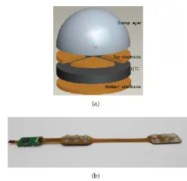
Quantum Tunnel Composite (QTC) sensors can change their properties from insulators to conductors under com-pression [17]. QTC sensors are more technologically ad-vanced compared to piezoresistive and capacitive sensors. The metal particles in QTC get so close to each other that quantum tunneling (of electrons) takes place between the particles. Using QTC material, Zhang et al. 2013 [72] (Figure 4) developed a flexible tactile sensor for an an-thropomorphic artificial hand with capability of measur-ing shear and normal forces. The sensor has sensitivities of 0.45mV/mN in x- and y-directions and of 0.16mV/mN in z-directions, and dynamic ranges up to 8N in z- and y-directions and 20N in x-direction. QTC-based tactile sensors [73] were integrated with previous versions of the Shadow robot hand [74] and used in the tactile glove for the Robonaut hand [75]. The sensors have linear response (please refer to sensor outputs w.r.t normal force in [72])
Figure 4: Quantum Effect Tactile Sensing: (a) structure of a tactel of the QTC based tactile sensing array with capability of measuring shear and normal forces [72]; (b) the flexible tactile sensing array for a finger of an anthropomorphic robot hand with the tactels that can measure shear forces [72].
and a dynamic range starting from 0 to 22N which out-perform the piezoresistive sensor with a maximum force of 5 N [31] in terms of the dynamic range. These sensors suf-fer from wear and tear of and, therefore, their sensitivity decreases as in the case of the piezoresistive sensors. To the best of our knowledge, for the tactile sensing materi-als within this category, there are no commercial products that are designed for use with robot hands.
2.1.5. Optical sensors
Optical sensing is based on optical reflection between mediums with different refractive indices. Conventional optical tactile sensors consist of an array of infrared light-emitting diodes (LEDs) and photo detectors (Figure 5(a)). The intensity of the light is proportional to the magnitude of the pressure [45]. Optical sensors can also be made sensitive to shear forces, e.g. Yussof et al. [37] devel-oped an optical three-axis tactile sensor for the fingertips of a two-fingered hand (Figure 5(b)). The sensor consists of 41 sensing elements made from silicon rubber, a light source, an optical fiber-scope, and a current charged cou-pled device (CCD) camera. With the optical tactile sen-sor, the hand is capable of manipulating a light paper box (Figure 5(c)). Kampmann et al. [76] embedded fiber op-tic sensors to a multi-modal tactile measuring system of a three-fingered robot gripper (Figure 7(d)). Xie et al. developed a flat 3x3 optical tactile sensor array (Figure 5(d)) with elements of the sensor that are magnetic reso-nance compatible for use in Magnetic Resoreso-nance Imaging [77]. Johnson et al. [78] proposed a novel "GelSight" tac-tile sensor to capture surface textures using an elastomer coated with a reflective membrane and a camera with res-olution of up to 2 microns. (Figure 5(e)). A fingertip with a "GelSight" (Figure 5(f)) tactile sensor can measure the surface roughness and texture, the pressure distribution,
Figure 5: Optical Tactile Sensors: (a) an optical tactile transducer based on the principle of frustrated total internal reflection [45], (b) a structure of optical three-axis tactile sensor: a displacement of a sensing element fixed on flexible finger surface causes changes in light propagation in opto-fibers [37], (c) fingers with the sensitive optical sensors manipulating a light paper box [37], (d) photo of an optical 3 x 3 tactile array with magnetic field compatibility [77], (e) "GelSight" optical sensor consisting of a piece of clear elastomer coated with a reflective membrane senses the shape of the cookie surface [79], (f) finger configurations of the "GelSight" sensor [79].
and even a slip [79]. Another example of an optical tactile sensor with transparent elastomer material is presented in [80], where an LED and a photo-diode distant from each other are placed against a reflecting (contact) planar sur-face. When surface deforms it causes changes in reflected beams. Similar concept is used in the OptoForce sensors [81]. These sensors are based on the use of infrared light to detect deformation of the contact surface, which in turn transforms to force. The forces in three dimensions are estimated from measurements of four photo-diodes that surround one infrared source. The reflecting surface has a semi-spherical shape.
Sensors within this category have good spatial reso-lution, sensitivity, high repeatability and immunity from electro-magnetic interference [15]. The disadvantages of these tactile sensors are their relatively big size, high-power consumption and high computational costs [10]. 2.1.6. Sensors based on barometric measurements
Tactile sensors within this group use pressure trans-ducers that have been long used for measuring the
pres-Figure 6: Sensors based on barometric measurements: (a) the struc-ture of a tactile sensing cell with a barometer and silicon rubber (b), the TakkStrip tactile array of these cells [87], (c) custom shaped array of the pressure sensing barometers of the iHY hand [42], (d) micro-vibration sensing system based on a fluid pressure sensor of the BioTac tactile sensor [83].
sure in liquids and air [45]. Use of liquid inside a tac-tile sensor allows getting high frequency response and de-formability of the sensor at the same time. A liquid is used as propagation media for vibrations, which are rep-resented by changes in pressure value. This approach takes advantage of the conventional pressure sensors, as for example the digital barometer [82]. Wettels et al. [19] introduced the sensing system that incorporates electro-conductive fluid to produce both constant and dynamic signals (Figure 6(d)). Micro-vibrations, caused by either motion over textured surface or slippage at any contact point, propagate as sound waves through the liquid media to a pressure transducer [83]. The bandwidth of the sen-sor is 1 kHz, which makes the sensing system well suitable for slip detection applications. The sensor is embedded
in the multi-modal biomimetic �BioTac fingertip sensorR
from SynTouch LLC [84].
In [85], no liquid is used as a propagation media, a barometer is instead molded within a silicon rubber in each tactel. The rubber acts as a membrane (Figure 6(a)) . Once the rubber is deformed due to the contact with an environment, it causes changes in the pressure values of the barometer. Using the same digital barometer, Odhner et al. [42] developed a tactile sensor array (Figure 6(c)) with a spatial resolution of around (3 − 5mm), sensitivity 1mN, and dynamic range up to 4.9N for a three-fingered robot hand [42].
Sensors involving liquid and barometers have high fre-quency response [86]. Sensors with silicon rubber and barometer are low-cost, but has low frequency response [85] as a result of the elasticity of the silicon rubber. Hence, the use of a liquid as a propagation media is more suitable when frequency response is of importance.
2.1.7. Multi-modal Tactile Sensors
To match the human hand’s different types of tac-tile sensing modalities (thermal, fast adapting and slow adapting afferents) [6] as close as possible, a robot hand should be equipped with multi-modal tactile sensors. Cur-rent multi-modal tactile sensing systems incorporate static pressure distribution arrays, dynamic tactile sensors, ther-mal sensors, and proximity sensors. The BioTac finger-shaped sensor array (Figure 7a,b) provides information about the contact forces, microvibrations, and tempera-ture produced during contact with external objects [19]. Some tactile sensors have the ability to sense dynamic and static contact forces since they have been constructed us-ing a combination of piezoresitive and piezoelectric ma-terials. Examples of such material include piezoresistive rubber with PVDF (Figure 3(b)) [24] that is integrated with an anthropomorphic fluidic hand [70] and pressure variable resistor ink with PVDF that is integrated with a four fingered robot hand [88]. Another hybrid sensing system with similar combination of dynamic and static transducers combines carbon micro-coil touch sensor and a force tactile sensor [89]. Hasegawa et al. integrated proximity and pressure sensors on the fingertip (Figure 7(c)) to enhance autonomous grasping [90]. Optical sen-sors also found their application in the multi-modal ap-proach. A three-fingered robot gripper described in [76] incorporates optical sensors and combines measurements of absolute forces by strain gauge sensors, dynamic forces by piezoelectric sensors, and force distribution by fiber op-tic sensors, as shown in Figure 7(d). Unlike the above multimodal sensors, in which locations of sensing units are known, a sensing system of a robot fingertip proposed by Hosoda et al. [91] has random distribution of the sens-ing units. Similar to [24], the senssens-ing system consists of piezoresistive and piezoelectric sensors to measure static forces and vibrations. The piezoelectric sensors are placed at a skin layer and inside the fingertip thus giving possi-bility to measure internal vibrations. The only drawback of the multimodal tactile sensors is their size.
2.1.8. Structure-borne sound tactile sensors
Vibrations and waves in solid structures are sumrized by the term "Structure-borne sound" [92]. In ma-nipulation tasks, structure born sounds occur at the ini-tial contact of a manipulated object with the environment or during the slippage. Accelerometers and microphones can be used as detecting devices. In pick-and-place ma-nipulation tasks, these structure born sounds can serve as indicators to trigger the placement of the object by the ma-nipulator. Romano et al. [38] use a high sensitive 3-axis accelerometer in the base of PR2 robot gripper in order to detect the contact of the object with the table and to release the object. Earlier, Kyberd et al. [32] integrated a microphone with an anthropomorphic prosthetic hand for automated grasping.
Sensors within this group have wide bandwidth, but are suitable for dynamic measurements only. However, in
Figure 7: Multimodal Tactile Sensors: (a) schematic of the biomimetic BioTac tactile sensor with 19 electrodes, fluid pressure sensor and thermometer [84], (b) photo of the multimodal BioTac tactile sensor, (c) combined tactile-proximity sensor that can mea-sure both the distance to an object and the contact presmea-sure [90], (d) drawing of a multi-modal tactile sensing module consisting of optical and piezoresistive sensors [76].
a close proximity of an object, it is possible to estimate the distance to the object by comparing a level of an environ-mental acoustic noise and a level of noise within the sensor as has been shown by Jiang et al. [93]. The presented con-cept of the sensor is based on Seashell Effect - increase of a level of noise in cavities due to resonance of sound waves and intrinsic resonance frequency of a cave. The sensor incorporates a cavity and a microphone located inside the cavity. The cavity has its own resonance frequency that depends on both the structure of the cavity and the dis-tance from an object to be grasped.
Data stream coming from tactile sensors has different physical meanings for different transduction technologies. In general it can be dynamic or static according to the time response and may represent an array of data, vector or scalar value. Hence, data acquisition from different sen-sors has its own approaches as discussed in the following section.
2.2. Tactile data types and acquisition
Force torque sensors installed on the fingertips of a robot hand provide with force and torque values in each
direction in R3. A contact point location can be estimated
from these forces and torques as long as the shape of the fingertip is known [26]. The measured forces and torques can then be used for force control (Section 4.4) and in haptic object recognition (Section 4.2).
Table 2: Tactile sensing types: advantages and disadvantages of ma-jor sensor types. Abbreviations for the names: PRes. - piezoresistive sensors, Cap. - capacitive, PEl. - piezoelectric sensor, Opt. - optical sensors, BarS. - sensors based on barometric measurements, MultiM. - multimodal sensors, SoundS. - structure borne sound sensors.
Type Advantages Disadvantages
PRes. Many commercial solutions exist, simpler for manufacturing, can be flexible. Non-linear response, temperature and moistness dependence, fatigue, permanent deformation, hysteresis Cap. A number of commercial solutions, can be flexible, may have higher bandwidth than PRes. Susceptibility to electro-magnetic noise, sensitivity to temperature, non-linear response, hysteresis.
PEl. bandwidthVery high dependence, dynamicTemperature
sensing only QTC Linear response, higher dynamic range (w.r.t Cap. and PRes)
More complex for manufacturing (w.r.t
in Cap. and PRes)
Opt.
High spatial reso-lution, high sensitivity, repeatability, immunity to EM noise Bulky, high-power consumption, high computational costs BarS. (fluid) High bandwidth, high sensitivity, temperature and moistness independence Low spatial resolution
SoundS. High bandwidth Dynamic sensing only
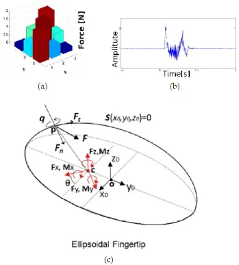
Tactile sensors with fast response (such as accelerom-eters, microphones, piezoelectric and capacitive technol-ogy based sensors, and barometers with fluid media) pro-vide information about vibrations at the contact point (see Figure 8 (b)). Information about vibrations can be fur-ther used for slip detection and haptic object exploration (Sections 4.2.2 and 4.1.2). The dynamic response of the tactile sensing arrays is limited by the sampling rate of reading devices. In [39], the sampling rate of data acqui-sition board is 10 kHz, while in [9] the signal bandwidth is limited by the sampling rate (300 Hz) of a commercial capacitance-to-digital-converter [67]. Figures 9(a) and (b) show schematic diagrams of reading devices for dynamic capacitive and piezolectric PVDF sensors.
Information from pressure sensing tactile arrays can be
Figure 8: Tactile sensing signal types: (a) a two-dimensional pres-sure distribution of a tactile sensing array, where the sensing tactels are located on xy plane and force/pressure is measured along z-axis [77]; (b) dynamic tactile signal from a single tactel or from an en-semble of tactles, which can be acquired during a slippage [24]; (c) 6 DoF force/torque sensor measurements in the ellipsoid-shape finger-tip [26] including normal forces in each direction Fiof the Cartesian
space, torques Mi, contact point P , forces and torques at contact
point F and q.
treated as a gray-scale image in computer vision [40] (see figure 8(a)). Although some tactile arrays may have tac-tels (Figure 4(a)) that can measure pressure in the three-dimensional space as in [72], the value of each tactel in most of the current tactile sensors is proportional to ap-plied normal pressure only. Tactile sensor arrays provide information about contact shape and pressure distribu-tions [41].
In capacitive and piezoresistive sensors, data from each tactel can be acquired either directly, which means that a high amount of wires is required, or by using a multiplexing circuit (Figure 10(c)), which decreases twofold the number of wire connection.
Piezoresistive tactile arrays consist of a common elec-trode, of sensing electrodes that are arranged as a ma-trix, and of conductive rubber in between. Pressing on the sensor’s surface provides an image of the applied pres-sure profile [53]. Figure 1(f) illustrates the image of the sensing array which is produced when a spherical object is pressing the tactile surface. Tactile images can be used for contact pattern recognition [94], grasp stability estimation [95], object classification [49], and tactile servoing [31].
For tactile sensing arrays, data acquisition involves the usage of analog to digital converters (Figure 9(d)) as well
Figure 9: Tactile sensing reading circuits: (a) the condenser mi-crophone circuit for capacitive sensors [9]; (b) a circuit for utilizing piezoelectric PVDF film as a stress rate sensor [9]; (c) signal condi-tioning and voltage multiplexing for a 3 x 3 tactile sensing array [49]; (d) the voltage-divider circuit for a pressure conductive rubber [39]; (e) network structure of the iCub tactile sensing skin using CAN-bus for connecting tactile sensing patches, 12 tactels in each patch, with a main processing unit [44].
as of microprocessing units for polling each tactel [18]. The capacitance of capacitive tactile sensors can be measured by commercial CDCs chips. The CDC chips can include
I2C serial interface. Digital barometers such as the
abso-lute digital pressure sensor "MPL115A" [96] that is used
in the iHY robot hand [42] has also I2C serial interface.
Communication with processing units can be realized via different transmission protocols (e.g. controller area net-work (CAN), and universal serial bus (USB), RS232). In iCub skin [44], local measurements are sent by an on-board processing unit over a CAN bus (Figure 9(e)). Multimodal tactile sensing data in the BioTac sensor [19] is acquired by the PIC microprocessor and sent to the host process-ing unit over serial peripheral interface (SPI). In order to minimize memory use of micro-processing units, data com-ing from sensors can be preprocessed by signal condition-ing circuits, which can be implemented as system on chip (SOC) or system in package (SIP) [18].
In some specific applications, for example in fast reac-tion to slip [24], signals from tactile sensors can be ana-lyzed and processed within a controller without sending information to the host computer. In most of the appli-cations, middleware and high-level software installed onto the main processing unit is used to compute acquired data and control the system. For these purposes versatile open source and commercial robot control platforms are avail-able: in [30], robot operating system (ROS) [97] is used to control Shadow robot hand [98], robot platform (YARP) [99] is used to control iCub humanoid robot [100]; the con-trolling operating system dSPACE from dSPACE Co. is used in [39] to control high speed-robot hand [101] in real-time and C++ libraries of open Robot control software (OROCOS) [102]. Among open source robot control plat-forms, ROS is the most widely used and supports both simulation (Gazebo simulator) and control of the Shadow hand, the Barret hand and many other manipulators and robots.
3. State of the art tactile sensor integration with robot hands
In this section we review the existing robot hands equipped with tactile sensors and discuss several issues related to the integration process.
3.1. Issues related to the shape of the attachment surface Mounting tactile sensors on the palm, a jaw grippers or on fingers with flat surfaces is relatively straightfor-ward, one of the simplest ways involving using a double side tape. Figure 10(a) shows an experimental setup con-taining the Shadow Hand and the Tekscan tactile sens-ing system (Model 4256E), which was used for contact shape recognition [94]. In another manipulating setup, off-the-shelf capacitive arrays have been installed on the fingertips of the four-fingered "Allegro" robot hand (Fig-ure 10(b)). Fig(Fig-ure 10(c) illustrates the Robotiq adaptive
Figure 10: Simple integration of tactile sensing arrays: (a) the Tekscan tactile sensing system consisting of 349 taxels with the Shadow robot hand [94], (b) the Allegro robot hand with PPS RoboTouch capacitive arrays [64], (c) the Robotiq adaptive gripper with sensor suite installed on the contact surface [65]
gripper covered by capacitive pressure sensing arrays used for the recognition of the type of the slip [65]. Attaching tactile sensors on fingers and fingertips is a complex pro-cess as curved surfaces with small radius of curvature have to be taken into account. Tactile sensors should be either: a) flexible and appropriately shaped to envelop a given surface, as in iCub tactile fingertip sensors (Figure 11(a, b) [103]; b) rigid and shaped as an attachment part, e.g. [34] or [104] where a 3D-shaped tactile sensing array and an ellipsoid F/T sensor (Figure 11(c) and (e) ) replace the fingertips of the Shadow robot hand [98]. In another ver-sion of the Shadow robot Hand with the integrated BioTac multimodal tactile sensor, each finger loses one DoF (Fig-ure 11(d)), – the sensor is as big as the two last links, distal and middle phalanges of the human index finger.
The shape of the links of the fingers in robot hands is different from the shapes of human finger phalanxes. The proximal and middle links of fingers in artificial robot hands have a smaller contact surface than those of hu-mans, a fact that significantly decreases the sensing area and causes difficulties with attachment. Figure 12 shows the difference between sensing areas on the middle and proximal links of a human finger and a robot finger. Cur-rent artificial tactile sensors are not as flexible as human skin and cannot cover the empty space between the links for closing the finger of robot hands.
3.2. Wiring issues
A key issue in tactile sensing array integration is the amount of wires required to read and transmit the data from the sensing arrays. Any increase in the number of tactels in tactile sensing array causes an increase either in the number of wires or/and on the time needed for data acquisition from sensors. A serial data communication can be used to reduce the number of connections. For exam-ple, in the iCub skin, communication was implemented through I2C serial bus, where only four wires were con-nected to the PCB of the sensing array [44]. However, se-rial access of data is slower than parallel access. In iCub,
Figure 11: Advanced integration of tactile sensors on the robot fin-gertips: (a) a flexible PCB for a capacitive tactile sensing array with 12 taxels designed for the iCub humanoid robot [103],(b) the iCub flexible PCB wrapped around the inner support of the fingertip [103], (c) a 3D-shaped rigid tactile sensing array with 12 sensing elements attached to the fingertip of the Shadow robot hand [34], (d) the Bio-Tac multimodal tactile sensor installed on the Shadow robot hand by replacing two last links of the finger [43], (e) ATi nano 17 force/torque sensor on the fingertip of the Shadow robot hand [30].
the skin sampling rate for each tactel decreases from 100 Hz to 25 Hz as the number of tactels increases. If the real-time pressure distribution is of interest, as for exam-ple in tactile servoing [31], the serial data access may fail to produce time-series images of the contact image. The parallel access of data provides higher acquisition rate, but requires a higher number of wires than the serial one. Em-ploying advanced addressing schemes is a way of reducing the number of wires needed in the parallel access schemes. For example, in the row-column scheme [49] n + m wires are needed for n ∗ m array of sensors instead of n ∗ m + 1 wires required in the schemes with one common ground [34]. Other approaches dedicated to reducing wiring issues include wireless data and power transmission and imple-mentation of a decentralized data pre-processing of tactile signals [24], [76].
3.3. Integration steps
One way to integrate tactile sensors in robot hands is in using tactile gloves. A number of tactile data gloves have been designed for use in human grasping applications rather than in autonomous manipulations tasks, e.g. [54]. However, tactile data gloves could be worn on robot hands,
Figure 12: Difference in contact surfaces between a human finger and a robot finger [105].
Figure 13: Tactile data glove based on conductive rubber (a) and the tactile information from the data glove during a grasp (b) [54]. as in the Robonaut robot hand [106] capable of sensing 19 points of contact. Commercial tactile data gloves are available from Tekscan [57] and CyberGlove [107]. Figure 13 shows a tactile data glove based on piezoresistive and conductive fabrics.
A more effective way of integrating tactile sensors is to embed them into the robot hand. The embedding pro-cedure of the tactile sensing skin within the robot hand involves the following steps [44]:
• definition of the surface to be covered by the available 3D computer-aided-drawing (CAD) model or by means of a 3D scanner.
• manufacturing of the supporting part using tactile sens-ing PCBs. This part is to be attached to the robot hand. The use of a 3D printer can facilitate the manufacturing procedure. This step is not applicable if integration of fingertip-shaped tactile sensors is required, which involves changing the structure of the finger.
• identification and wiring of the sensing elements. • gluing the sensing elements down on the supporting part. • covering the sensing elements with flexible material, e.g. silicon rubber. For a specific surface shape , custom molds should be designed.
3.4. Robot hands equipped with tactile sensors
This section presents an overview of manipulating plat-forms with sensorized artificial hands, developed in the framework of research projects in autonomous manipula-tion and tactile sensing applicamanipula-tions. A list of these plat-forms is presented in Table 3 and a summary with com-ments about the different hand/sensor combinations are given in Table 4.
In [49] an 8x8 tactile array based on piezoresistive rub-ber has been attached onto the grippers of the 3-fingered Schunk SDH hand for classifying deformable objects. Out-standing in speed performance, the Lightweight High-Speed Multifingered Hand System [101] integrates Center-of-Pres-sure (CoP) sensor for the force meaCenter-of-Pres-surements and PVDF based high sensitive tactile sensor for slip detection, as shown in Figure 14(a) [39]. Commercial 3-finger Schunk SDH hand [109] with integrated Weiss Robotics piezoresis-tive tactile sensors [58] incorporates a 14x6 array on each distal link and a 14x7 array on each middle link. The Uni-versal robot hand [35] has 102 tactels on fingertips and 70 tactels on the rest of the links. In contrast to the serial connection of sensors present in the iCub skin [44], each tactile array has its own connection with the acquisition board (Figure 14(b)).
Capacitive arrays from Pressure Profile System [66] have been integrated with PR2 robot grippers [95]. The sensor array on the PR2 robot has tactels in back and front, on left and right sides, and finally on the tip. Very sensitive tactile sensors with fibers connected to capacitive sensor akin to animal whiskers have been integrated with the parallel jaw gripper of a humanoid robot platform to explore object surfaces and for human-robot interaction purposes [113]. The Barret hand [114] has capacitive tac-tile sensors on the tips, distal link and palm.
The "Takktile" arrays [87] based on barometric mea-surements have been integrated with the iRobot-Harvard-Yale (iHY) Hand [42]. The hand is covered by an array of 48 tactels on the palm, a 2x6 array on proximal links, and a 2x5 array on distal links with two of the tactels on the tip (Figure 14(c)).
An optical tactile array of 41 tactels with the ability to measure normal and tangential forces has been placed on the tips of a two-fingered robot system [13]. A multi-modal tactile sensing system may require a larger space, especially if optical tactile sensors are incorporated within it. Figure 14(d) illustrates the robot hand with the multi-modal sensing system [76]. Force torque sensors are placed at the base of each finger, not on the fingertips as in the Shadow hand [104]. The three-axis opto-force sensors [81] can be installed on the tips of the Barret Hand [114].
In [117], photo-reflectors have been attached to the three-fingered robot to provide proximity information for preshaping the fingers during grasping. The Seashell ef-fect sensors [93], which also provide proximity information, have been installed on the PR2 robot grippers.
The tactile sensing system for the DLR robot hand-arm system [116] is designed as large scale tactile skin using the
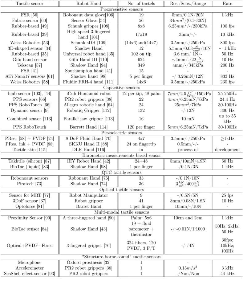
Table 3: The list of tactile sensors that have been integrated with robot hands. Number of tactels (No.), spatial resolution (Res.), sensitivity (Sens.), dynamic range (Range) and data acquisition rate (Rate) are provided where possible.
Tactile sensor Robot Hand No. of tactels Res./Sens./Range Rate
Piezoresistive sensors
FSR [56] Robonaut data glove[106] 19 5mm/0.1N/20N 1 kHz
Fabric sensor [60] Sensor Glove [54] 56 34mm2/(0.1–30N)
-Rubber-based [49] Schunk gripper [108] 8x8 6.25mm2/-/250kPa 100 fps
Rubber-based [39] High-speed 3-fingeredhand [101] 17x19 3mm/-/- 10 kHz
Weiss Robotics [53] Schunk sDH [109] (14x6)and(14x7) 3.5mm/-/250kPa 800 fps
3D-shaped sensor [34] Shadow Hand 12 5.5mm/0.03 N
cm2/10N ∼ 1 kHz
Rubber-based [35] Universal robot hand [35] 102 on tip 3.6 mm/ 1N/- 50 Hz
Gifu hand sensor Gifu Hand III [110] 624 ∼4mm/-/22 N
cm2 10 Hz
Tekscan [57] Shadow Hand [94] 349 4mm/-/345kPa 200 Hz
FSR [41] Southampton hand [41] 15 -
-ATi Nano17 sensors [61] Shadow hand [98] 5 per finger -/ 3.26mN/12N 833 Hz
Weiss Robotics [58] Fluidic FRH-4 hand [111] 14x6 3.5mm/-/250kPa 230 fps
Capacitive sensors
Icub sensor [103], [44] iCub Humanoid robot 12 per tip, 48-palm 7mm/2.5f F
kP a/150kPa 25-250Hz
PPS sensors [66] PR2 robot grippers [38] 22 4mm/6.25mN/7kPa 24.4 Hz
PPS RoboTouch [66] Allegro robotic hand [64] 24 25mm2/7kPa 30-100Hz
Dynamic sensor [9] Robotiq Gripper [112] 132 -/-12N 300 Hz
Combined sensor [113] Parallel jaw gripper [113] 16 10 mN up to 35kHz
PPS RoboTouch Barrett Hand [114] 120 per finger 5mm/6.25mN/7kPa 30-100Hz
Piezoelectric sensors
PRes. [58] + PVDF [24] 8 DoF Fluid Hand [70] 4x7 3.5mm/-/250kPa ≥1kHz
PRes. ink + PVDF [88] SKKU Hand II [88] 24 on fingertip 0.5mm/-/-
-Tactile skin [115] DLR Hand [116] in process of development
Barometric measurements based sensor
Takktile (silicon) [87] iHY Robot Hand [42] 24+48 5mm/10mN/4.9N 50 Hz
BioTac (liquid) [83] Shadow Hand [98] 1 per finger -/0.1N/3N 1 kHz
QTC tactile sensors
Robonoaut sensors Robonaut Hand [75] 33 -/0.1N/10N
-Piratech [73] Shadow Hand [74] 36 3kN
m2/400kNm2
-Optical tactile sensors
Sensor for MRT [77] Robot Manipulator 9 -/0.5N/5N 25 fps
3DoF sensor [37] Robot gripper 41 3mm/0.08N/1.8N 10 Hz
Optoforce [81] Barret Hand 1 per finger 10mm/-/10N
-Multi-modal tactile sensors
Proximity Sensor [90] A three-fingered hand [90] Palm: 5x6 10cm and 2cm 1 kHz
BioTac sensor [84] Shadow Hand [43] barometer +19 + fluid
thermistor -/∼0.01N/1:1000
50Hz; 2kHz; 50 Hz
Optical+PVDF+Force 3-fingered gripper [76] 324 fibers, 120PVDF, 3 F/T -/-/4N 10kHz;30fps;
100Hz "Structure-borne sound" tactile sensors
Microphone Oxford prosthesis [32] 1 -
-Accelerometer PR2 robot grippers [38] 1 0.15m/s2 3 kHz
Figure 14: Three-fingered robot hands with tactile sensors: (a) a finger with tactile sensor of the 3-fingered high-speed robot hand [101], (b) assembly of tactile sensing arrays with a robot finger of the Universal robot hand with 3 movable and 2 immovable fingers [35], (c) schematic illustration of a finger of the iHY robot hand with embedded array of pressure sensors based on digital barometers placed inside the soft paddings of the fingers [42]; (d) schematic illustration of the integration of a multimodal sensing system with a three-fingered robot hand [76]
column-row net structure [115]. The robonaut hand has tactile feedback through the tactile data glove incorporat-ing piezoresistive technology [106] and QTC technology [75]. Figure 15(a) shows the Fluidic hand [70] with modi-fied version of the Weiss [58] sensors. The dexterous Gifu III robot hand (Figure 15(d)) has a sensing array of 859 taxels (Figure 15(c)) based on piezoresistive conductive ink [110]. An array of 24 conductive ink in combination with piezoelectric PVDF material has been used in the SKKU II robot hand [88]. The Shadow Hand [98] has different inte-grated tactile sensors: force/torque sensors (Figure 11(e)) [30], multimodal Biotac tactile sensors (Figure 11(d)) [43], 3D-shaped fingertip tactile sensors (Figure 11(c)) [34], and QTC sensors [74]. The robot hand of the iCub humanoid robot [100] has sensors on the fingertips and palm, but not on the middle and proximal phalanges (Figure 15(b).
Besides the five fingered robot hands, a number of an-thropomorphic robot hands with three fingers and thumb exist, including the "Twendy one" robot hand covered by capacitive tactile sensing arrays [118] and the "Allegro" robot hand [119] developed by SimLab Co.
3.5. Large area tactile skin
There is a high demand for manipulators and humanoid robots whose whole surface is covered with tactile sensors [18]. Large sensing areas embedded in robotic systems enhance human-robot interaction and are important for safety reasons. However, a large area tactile skin and the
Figure 15: Five-fingered robot hands with tactile sensors: (a) the fluidic robot hand with combined piezoelectric and piezoresistive tac-tile sensors that can sense high-frequency vibrations due to the ab-sence of electric motors [24], (b) the robot hand of the iCub hu-manoid robot with tactile sensors on the fingertips and the palm [44], (c) flexible tactile sensing arrays of the SKKU robot hand [88], (d) the SKKU robot hand [88]
concomitant increase in the amount of tactels present chal-lenges with regards to optimal data acquisition and wiring. The number of sensing tactels should be easily change-able for arbitrary surfaces to enhance the performance of the system. The iCub skin uses flexible triangle patches consisting of 12 sensing tactels each and off-the-shelf CDC AD7147 [67] (Figure 2(c)). Up to 16 triangle patches in series can be connected with each other but only one of them must be connected with the micro-processing unit which significantly reduces the amount of wires required. However, polling time increases proportionally to the num-ber of serial sensing elements. The iCub skin has been integrated in the child-sized humanoid robot KASPAR [120] and the autonomous humanoid robot NAO. iCub skin based on capacitive technology can sense applied pressure only.
Unlike the capacitive technology based iCub skin which can only sense applied pressure, HEX-O-SKIN measures temperature, vibrations and light touch [121]. Each patch of the HEX-O-SKIN is a hexagonal printed circuit board equipped with proximity sensors, accelerometers, thermis-tors, and a local controller. Each patch is less than 2 g in
weight, 5.1 cm2 in area, and 3.6 mm thick.
A limited number of tactile sensing skins has been in-tegrated in robotic manipulators for applications that re-quire tactile feedback, as in safe human-robot interaction. An example of an industrial manipulator covered with an array of capacitative proximity sensors is described in
Table 4: Sensors integrated with robot hands: advantages and disadvantages of major approaches.
Hand/Sensor Combination Advantages Disadvantages
3D-shaped array [34] & Shadow Hand; iCub robot fingertip
sensor [68]
Multiple point of contact, covers spherical shapes, wires - within
fingers
Normal force measurements only
Ellipsoid f/t sensor [104] & Shadow Hand; OptoForce [81] &
Barret Hand
Covers spherical shapes, high
sensitivity, shear forces. Single point of contact only,wires - outside of fingers
BioTac [84] & Shadow Hand Multiple point of contact, highbandwidth, wires - inside Last joint static (20 degrees)
Robonaut glove and Hand [106] Ease of replacement, low cost Not reliable compared to rigidlyattached sensors
Fabric sensor [54] Ease of replacement, stretchable Wear and tear off
Tactile sensing array (PPS [66], Tekscan [57], and etc.) & any
robot hand
Can be easily attached to any
flat and cylindrical surfaces Cannot cover spherical shape,wiring issues
Weiss Robotics [58] & any robot
hand; Takktile [87] & iHY hand Robust Flat surface only
SeaShell effect sensor (Cavity
with microphone & PR2) [93] Pre-touch sense Direct contact of the cavity withan object limits forces
Proximity Sensor [90] Pre-grasp sense Cannot measure very closeproximities
Accelerometer at the base of
robot grippers [38] Vibration detection Interference with electric motornoise
Microphone at the tips of the
Oxford Hand prosthesis [32] Vibration detection No interference with motornoises
Object Recognition Tactile Servoing
Force Control Grasp Stability
Tactile Sensors
Figure 16: Tactile sensing techniques. Tactile sensing in robot hands is used for object recognition, tactile servoing, force control and for assessing grasp stability.
[21]. A commercial industrial manipulator that incorpo-rates 118 proximity sensors is shown in [122]. Research in design of multi-fingered dexterous robot hands, being previously focused on prosthetic hands only, has surged in recent years. Various dexterous robot hands were de-veloped in research laboratories and became commercially available [74], [118], [119].
4. Computational Techniques in Tactile Sensing Ap-plications
In the robotics literature, tactile feedback has been widely used for telemanipulation, haptic devices, and legged robots [123]. In event-driven manipulation, tactile sig-nals have been used for detection of the current manip-ulation phase (contact/no contact, rolling, sliding) [124].
The use of tactile information for object exploration and recognition, material classification, and slip prediction has recently become rather popular as is reflected in [40], [95], [23], [19].
In robot hand applications, tactile signals are used to recognize objects, control forces, grasp objects, and to servo surfaces (Figure 16). Each of these applications will be discussed in following sections. The major computa-tional techniques used in these applications are illustrated in (Figure 17). As discussed in the Section 2.2, differ-ent tactile sensor types have differdiffer-ent sensing quantities, including force vectors, vibrations, and contact patterns. These quantities are then subjected to various computa-tional techniques. The same computacomputa-tional technique may be used in a number of applications, as it illustrated in the latter figure.
4.1. Grasp stability and slip detection
Grasping is one of the basic skills service robots and industrial manipulators are expected to have. Before per-forming a grasping procedure, a robot must plan the grasp. Grasping is a complex process for robot hands even if ob-ject parameters such as shape, position, physical proper-ties are known. When the properproper-ties are known, analytical approaches involving force and form closures can be em-ployed to perform grasping [125]. In unstructured
environ-Figure 17: Overview of computational techniques applied to tactile sensing signals in the reviewed robot hand applications. Each tactile data type is shown on the left. The computational techniques applied to the tactile signal are shown in the middle. Different applications of sensorized robot hands exploiting these techniques are shown on orbital on oval blocks. Arrows indicate only the major techniques of deriving information.
ments, object parameters are uncertain, which makes the grasping task even more difficult and presents a big chal-lenge for grasp stability approaches. A detailed review of all grasping techniques is out the scope of this paper and can be found in previous papers [126], [127].
In some approaches, the robot grasping procedure could be simplified by using proximity sensors on fingertips [128]. There are two main approaches of robot grasping that in-volve tactile feedback. One approach treats grasping as a control problem and does not consider hand kinemat-ics or assumes simple hands like grippers [39]. Another approach makes use of both model based grasp planning and force feedback to address the problem of grasping with dexterous robot hands that have more dof than grippers [25].
Regarding tactile sensor types and the way of process-ing the data, there are three different techniques for assess-ing grasp stability at the current state-of-the-art: friction cone based techniques, vibrations based techniques, and tactile images based techniques. Each of the technique is discussed in following.
4.1.1. Friction cone estimation for the slip event
The friction coefficient of surfaces and the load con-ditions are very important in grasping. When humans pick up an object, they take into account these parame-ters and adjust grasping forces based on tactile feedback during manipulation. The stability of a grasp is
evalu-ated by the ratio of normal, Fnorm, to tangential, Ftang,
reaction forces and static coefficient of friction µf
(Fig-ure 18(a)). Maintaining objects within the friction cone, to preclude slippage, is ensured by the following
condi-tion [125]: 1 < µf × FFnormtang. The tangential force can
be obtained by force/torque (F/T) sensors, for example ATi Nano 17 [61], whereas most of the current pressure sensing arrays can measure normal pressure only (Figure 8(c)). In [86] tangential forces are computed by apply-ing a Kalman filter to the data of the pressure sensapply-ing arrays of a bio-mimetic tactile sensor. The sensor con-sists of conductive fluid and electrodes placed in different places of the fingertip. Hence, the sensor does not provide absolute force values. The Kalman filter integrates sig-nals from the electrodes to produce a force output. Other approaches can rely on dynamic friction models that al-low the prediction of an incipient slip. For example, using F/T sensors installed on the Barret hand [114], Song et al. [27] estimate the coefficients of the dynamic LuGre friction model of a contact with an unknown object through two exploratory motions. Break-away friction ratio (BF-ratio) is then computed to predict a slippage. Besides the trans-duction methods mentioned in Section 2.1, heat microflux detectors, which are mainly used for measuring objects’ thermal properties, can be used for detecting a slip [129]. The temperature at the contact point increases during the slip due to the energy dissipation at the presence of friction
![Figure 1: Piezoresistive Tactile Sensor Arrays: (a) illustration of resistance changes in conductive rubber [47],(b) nano-scale image of conductive rubber [48], (c) structure of piezoresistive tactile array [49], (d) piezoresistive fabric tactile sensor [5](https://thumb-eu.123doks.com/thumbv2/123doknet/14640160.549226/6.892.67.812.133.548/piezoresistive-illustration-resistance-conductive-conductive-structure-piezoresistive-piezoresistive.webp)
![Figure 5: Optical Tactile Sensors: (a) an optical tactile transducer based on the principle of frustrated total internal reflection [45], (b) a structure of optical three-axis tactile sensor: a displacement of a sensing element fixed on flexible finger surface](https://thumb-eu.123doks.com/thumbv2/123doknet/14640160.549226/8.892.472.821.121.395/optical-transducer-principle-frustrated-reflection-structure-displacement-flexible.webp)
![Figure 7: Multimodal Tactile Sensors: (a) schematic of the biomimetic BioTac tactile sensor with 19 electrodes, fluid pressure sensor and thermometer [84], (b) photo of the multimodal BioTac tactile sensor, (c) combined tactile-proximity sensor that can me](https://thumb-eu.123doks.com/thumbv2/123doknet/14640160.549226/9.892.477.822.120.472/multimodal-tactile-schematic-biomimetic-electrodes-thermometer-multimodal-proximity.webp)
![Figure 9: Tactile sensing reading circuits: (a) the condenser mi- mi-crophone circuit for capacitive sensors [9]; (b) a circuit for utilizing piezoelectric PVDF film as a stress rate sensor [9]; (c) signal condi-tioning and voltage multiplexing for a 3 x 3](https://thumb-eu.123doks.com/thumbv2/123doknet/14640160.549226/11.892.75.406.167.956/tactile-circuits-condenser-crophone-capacitive-utilizing-piezoelectric-multiplexing.webp)
![Figure 10: Simple integration of tactile sensing arrays: (a) the Tekscan tactile sensing system consisting of 349 taxels with the Shadow robot hand [94], (b) the Allegro robot hand with PPS RoboTouch capacitive arrays [64], (c) the Robotiq adaptive gripper](https://thumb-eu.123doks.com/thumbv2/123doknet/14640160.549226/12.892.473.821.117.535/integration-tekscan-consisting-allegro-robotouch-capacitive-robotiq-adaptive.webp)
![Figure 12: Difference in contact surfaces between a human finger and a robot finger [105].](https://thumb-eu.123doks.com/thumbv2/123doknet/14640160.549226/13.892.128.363.118.336/figure-difference-contact-surfaces-human-finger-robot-finger.webp)
![Figure 15: Five-fingered robot hands with tactile sensors: (a) the fluidic robot hand with combined piezoelectric and piezoresistive tac-tile sensors that can sense high-frequency vibrations due to the ab-sence of electric motors [24], (b) the robot hand o](https://thumb-eu.123doks.com/thumbv2/123doknet/14640160.549226/15.892.75.415.126.446/fingered-fluidic-combined-piezoelectric-piezoresistive-frequency-vibrations-electric.webp)
