Data Acquisition System Design for the Alpha
Magnetic Spectrometer Experiment
by
Nicole Immorlica
Submitted to the Department of Electrical Engineering and Computer
Science
in partial fulfillment of the requirements for the degree of
Bachelor of Science in Computer Science and Engineering
and Master of Science in Computer Science and Engineering
at the
MASSACHUSETTS INSTITUTE OF TECHNOLOGY
January 2002
©
Nicole Immorlica, MMII. All rights reserved.
The author hereby grants to MIT permission to reproduce and
distribute publicly paper and electronic copies of this thesis document
in whole or in part.
Author .
MASSACHUSETTS NSTITUTE OFTECHNOLOGYJUL 3 12002
LIBRARIESDepartment of Electrical Engineering and Computer Science
January 18, 2002
Certified by..,
Peter Fisher
Professor
ThesivSupervisor
Accepted by
-...
Artliur C. Smith
Chairman, Department Committee on Graduate Students
Data Acquisition System Design for the Alpha Magnetic
Spectrometer Experiment
by
Nicole Immorlica
Submitted to the Department of Electrical Engineering and Computer Science on January 18, 2002, in partial fulfillment of the
requirements for the degree of
Bachelor of Science in Computer Science and Engineering and Master of Science in Computer Science and Engineering
Abstract
The Alpha Magnetic Spectrometer (AMS) experiment will search for and study anti-matter, dark anti-matter, and cosmic rays from the International Space Station (ISS). The experiment consists of several arrays of subdetectors designed to record necessary data autonomously. The data acquisition system (DAQ) is a distributed system of processors of modest power which collect, correlate, and transmit the massive amounts of data produced by the subdetectors. In addition, the DAQ permits proper maintenance of the key AMS components. In order to design and test this complex distributed system, a simulation was written which closely mimics the DAQ. This project covers the development of the DAQ system design and the simulation testbed.
Thesis Supervisor: Peter Fisher Title: Professor
everybody knows the boat is leaking. everybody knows the captain lied.
Acknowledgments
My advisor, Prof. Peter Fisher, provided me with excellent guidance and
encourage-ment throughout this thesis. Thanks to him, I was able to explore an intriguing ap-plication of computer science in experimental physics. His many technical comments and aid in the implementation of the simulation framework user interface greatly facilitated my understanding and completion of this thesis.
This thesis would not have been possible without the support of the entire AMS group and their enthusiasm about including me in the group. In particular, I want to thank Andrei Kounine for his help in creating the simulation framework, and Alexei Lebedev and Mike Capell for their help in formulating the logic of the system.
Finally, I want to thank everyone in the AMS collaboration and my friends in Europe for making this past year captivating and enjoyable.
Contents
1 Introduction 15
1.1 Experimental Setup . . . . 16
1.2 Data Acquisition . . . .. . . 17
1.3 Summary . . . . 20
2 DAQ System Overview 23 2.1 Constraints . . . . 25
2.1.1 Low Power . . . . 25
2.1.2 Data Corruption . . . . 25
2.1.3 Unreliable Links . . . . 26
2.2 Architecture . . . . 26
3 DAQ System Design 29 3.1 Relationships . . . . 30
3.1.1 Masters and Slaves . . . . 30
3.1.2 Girlfriends and Boyfriends . . . . 34
3.1.3 Messages . . . . 35
3.2 Tasks . . . . 39
3.2.1 System Monitoring . . . . 40
3.2.2 Event Building . . . . 42
4 DAQ System Simulation 49 4.1 Software Documentation . . . .. . . 49
4.1.1 Software Design . . . . 49 4.1.2 Software Implementation . . . . 52 4.2 Simulation Analysis . . . . 64
List of Figures
1-1 AMS detector . . . .
1-2 DAQ system diagram . . . . .
2-1 Creation of an event message
3-1 3-2 3-3 3-4 3-5 3-6 3-7 3-8 4-1 4-2 4-3 4-4 4-5 4-6
Ports and links ... ...
Directed system graph . . . . Communication errors . . . . Example request . . . . Exam ple reply . . . .
System monitoring Program K state diagram.
Event building . . . . Event building Program K state diagram . . . Is-a/has-a NZ relationship diagram . . . .
Module class definition . . . . Module class main run loop . . . .
FEEMod request servicing routine . . . .
Communicator class definition . . . .
NZ graphical user interface . . . .
. . . . 18 . . . . 20 . . . . 24 . ... 30 . . . . 31 . . . . 33 . . . . 36 . . . . 38 . . . . 41 . . . . 43 . . . . 45 52 54 55 57 61 64
List of Tables
1.1 Number of channels per subdetector . . . . 3.1 System monitoring Program K transitions
3.2 Event building Program K transitions . . .
19 . . . . 4 2
Chapter 1
Introduction
The Alpha Magnetic Spectrometer (AMS) is a particle physics experiment that will study high energy cosmic particles from aboard the International Space Station (ISS). This experiment promises unprecedented sensitivity due to its location beyond the Earth's interfering atmosphere. Armed with the high-precision AMS data, AMS seeks to find experimental evidence of theoretically predicted but as yet unobserved phenomena.
Physicist Paul A.M. Dirac asserted in his Nobel Lecture of December 12, 1933 [6]
that, at the beginning of the universe, the amount of matter and anti-matter was equal. Yet, the galaxy in which we live appears to consist entirely of matter. In support of his symmetry assertion, Dirac further conjectured in his Nobel Lecture that the universe contains anti-matter galaxies.
If they exist, anti-matter galaxies would follow the same physical laws as the well-understood matter galaxies. In particular, cosmologists expect anti-matter galaxies to include anti-supernovae. These anti-supernovae produce anti-elements such as anti-carbon just as supernovae produce elements. For every billion anti-elements expelled by an exploding anti-supernova, one might escape the anti-galaxy from which it originated and wander into our own galaxy.
Until now, attempts to detect these wayward anti-elements have been unsuccessful.
A major reason for the failure of some of these experiments is that they are located on
before reaching the surface of the Earth. Other experiments have been flown via balloons to the upper reaches of the atmosphere. However, the duration of a balloon flight is only 40 or 50 hours making it unlikely that an anti-particle will be observed. Some experiments have also been flown on satellites, but due to budget constraints they were too small to be successful.
AMS aims to circumvent these obstacles by orbiting AMS around Earth on the ISS
for three years. From this privileged position, AMS will gather detailed data about the many high energy particles which constantly barrel through space. Through careful analysis of the properties of each particle, we hope to find one of the elusive cosmically-originating anti-particles. A discovery of this sort would be a major breakthrough in physics. It would lend credibility to current theories of the Big Bang and support the widely accepted Grand Unified Theory which predict a symmetric universe.
1.1
Experimental Setup
The most important mission of AMS is to detect anti-matter. In order to achieve this goal, AMS warps the paths of particles with a large magnetic field. The charge of the particle determines the direction of its trajectory through the magnetic field. Since protons have positive charge whereas anti-protons have negative charge, matter and anti-matter will follow different trajectories through the magnetic field.
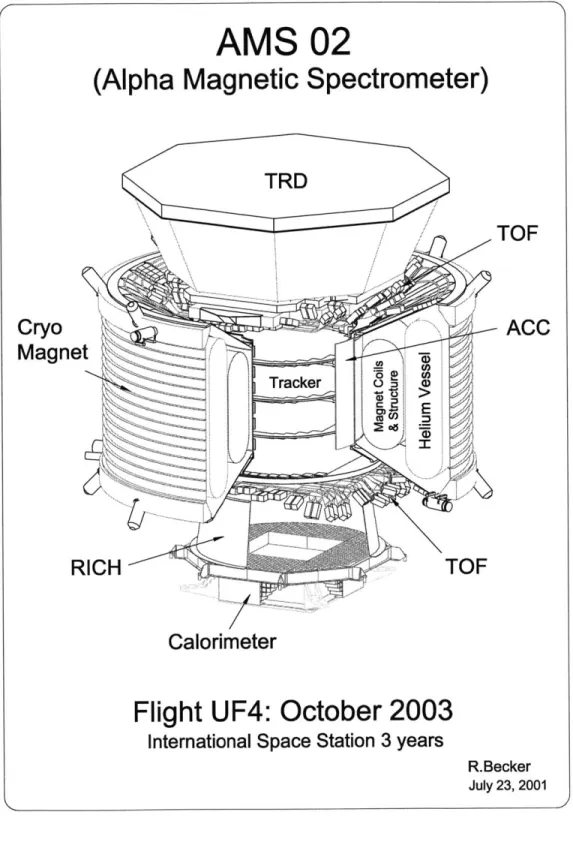
In order to detect and identify high energy particles, the AMS detector has a series of subdetectors which measure the energy and position of a particle (Figure 1-1). The ring-imaging Cerenkov detector (RICH), transition radiation detector (TRD), and the electromagnetic calorimeter (ECAL) utilize various physical processes to determine the energy of a particle [2]. Each subdetector is optimized for a particular energy range. The position of a particle is measured by the trackers. A strong magnet produces a uniform magnetic field with parallel field lines across the subdetectors. As a particle passes through the system, it hits the subdetectors and produces a
signal. The trackers can locate this signal to within 10 microns (10 x 10-6 meters),
combining data from all the subdetectors, we can reconstruct the path of a particle through the magnetic field and its energy.
However, this is not enough information to distinguish matter from anti-matter. In order to determine the direction in which the magnetic field warped the particle's path, we must know which tracker - the top tracker or the bottom tracker - a particle encounters first. This requires a notion of time. Time of flight detectors (ToF) are introduced for this purpose. The ToFs sandwich the trackers and record to within
100 ps when a particle passes through them. Assuming the particle is traveling at the
speed of light, it will take the particle approximately 3000 ps to traverse the detector. Therefore, the time measurements of the ToFs along with the information from the trackers completely determine the trajectory of the particle.
From the data gathered by the subdetectors, we can conclude the velocity, mo-mentum, energy, and charge of the particle. This information will allow us to answer questions about the existence of anti-matter, the type of anti-matter, and the inter-galactic propagation of anti-matter.
1.2
Data Acquisition
We expect around 3x10³ particles to bombard the detector each second. Of these,
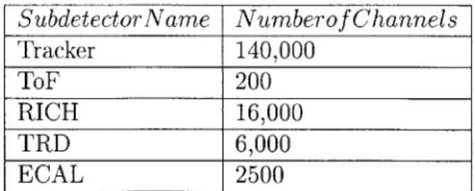
approximately 100 particles per second can be recorded. Each subdetector has series of channels that locate the position of the particle within the subdetector. There are many channels and every channel must be recorded (Table 1.1). Correspondingly, the subdetectors will produce data at 2 megabits per second. The DAQ is responsible for collecting, correlating, and transmitting this massive amount of data within the bandwidth constraint.
Every time a particle passes through AMS, all subdetectors produce data concern-ing that particle. Collectively this data is known as an event. Event data propagates through the DAQ system and gets packaged into an event message. The main pur-pose of the DAQ system is to guarantee consistency and completeness of these event messages subject to low power, data corruption, and unreliable links.
AMS 02
(Alpha Magnetic Spectrometer)
TRID
TOF
CryoACC
Magnet
Tracker 0 (RICH
TOF
Calorimeter
Flight UF4: October 2003
International Space Station 3 years
R.Becker July 23, 2001
Subdetector Name Numberof Channels Tracker 140,000 ToF 200 RICH 16,000 TRD 6,000 ECAL 2500
Table 1.1: Number of channels per subdetector
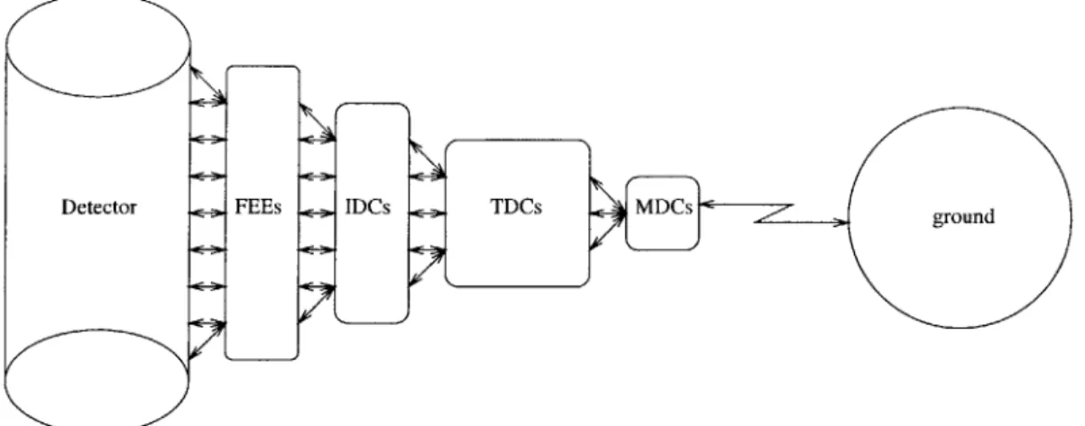
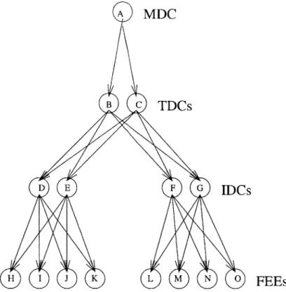
To accomplish this task, around 400 computers are arranged in a tree structure (Figure 1-2). The DAQ tree consists of four types of levels. At the root of the tree are the main data concentrator (MDC) computers. The MDCs interface with the controls on ground, providing the main link to the DAQ system. The intermediary nodes of the tree are the command distributor and data concentrator (CDDC) computers. These computers collect and transmit data to the root of the tree as well as pass commands towards the leaves of the tree. The top layer of CDDCs are called the top data concentrator (TDC) computers. Below the TDCs, the immediate parents of the leaves of the tree are the intermediary data concentrator (IDC) computers. IDCs share all the responsibilities of the TDCs and additionally prompt the leaves of the tree to read event data from the subdetectors. The leaves of the tree are the front end computers (FEE). They are connected directly to the subdetectors and are responsible for recording and digitizing detector data. In addition to this tree of computers, there are two auxiliary units which aid in the timing and synchronization of data collection. The fast trigger (FAST) examines the ToFs and sends a signal whenever the ToFs indicate that a particle has passed from one to the other taking at least 3 nanoseconds. The level one trigger (TRI), receives the FAST signal, selects which particles to record, and initiates data recording. All computers must have redundancy for safety and system maintenance purposes.
Users interact with the DAQ system via a system of computers on the ground.
All messages transmitted from the MDC to the ground are stored in a buffer. A
graphical user interface accesses this buffer and displays pertinent information to the user. This interface is also capable of transmitting commands from the user back to
Detector FEEs IDCs _ TDCs MDCs = / , gon
Figure 1-2: DAQ system diagram
the MDC.
1.3
Summary
The DAQ system is large, complex, and essential to the success of the AMS mission. The system must be designed as a whole with all components designed in parallel. Hardware limitations must be analyzed when designing the software; software re-quirements must be considered when designing the hardware. Every component of the system from the custom-built hardware to the design and implementation of the software must be thoroughly tested experimentally and verified by logical reasoning. Thus it is necessary to design and test the DAQ software before the existence of the
DAQ hardware.
This paper discusses the software design and preliminary tests made in advance of the hardware. Our results include an experimentally sound set of algorithms that achieve system goals subject to engineering concerns. We test our software design in absence of the hardware by writing normal and error-condition software simulations. The algorithmic correctness of the system is substantiated via informal distributed systems arguments. As a by-product of our simulation study, we have produced some highly reusable code both for the flight version of the MDC and for the ground
interface to the DAQ system. We demonstrate the performance of this code when used in conjunction with prototype hardware.
Chapter 2 develops a more concrete notion of DAQ system and engineering con-straints. Chapter 3 discusses the overall DAQ system design proposed by this project and provides an informal argument as for its correctness. Chapter 4 explains in de-tail the simulation software and test results and presents the reusable parts of the simulation software.
Chapter 2
DAQ System Overview
The DAQ system is designed to report particle data as measured by the AMS de-tectors. These particle trajectories, or events, are recorded in thousands of disjoint fragments. Each channel of each subdetector produces a fragment for every event. The event fragments are collated by the DAQ system to produce complete and co-herent event messages. By complete we mean a message for event E should contain all fragments corresponding to E, and by coherent we mean the message should contain no fragments not corresponding to E. The DAQ system must reliably and autonomously report these event messages.
When we require that the system be reliable, we mean that it should be able to collect data even in the presence of certain temporary and perhaps permanent failures of individual components. However, we do not require the system to correct failures autonomously. To implement user-intervention fault-tolerance, we require the system be self-monitoring: the system should monitor its own status and periodically report this status to the user. Furthermore, the system should be able to respond to user commands. Allowed commands include those that change the state of any system component (e.g. user may request a computer to power down or load new software) as well as those that observe the state of system components (e.g. user may request a report of the current memory content or temperature of a processor).
When we say the system should be autonomous, we mean that complete and co-herent event messages corresponding to "interesting" particles should be produced
FAST & TRI
i00
DAQ system Nobel prize
Happy scientist
particle
Figure 2-1: Creation of an event message
by the system without human intervention. There are several steps in this process.
First, the hardware must be able to detect events. Then, as there are too many events to record them all, a combination of hardware and software must suppress some of the less interesting events. When an event is detected and not suppressed, the corre-sponding data must be read from the subdetectors and digitized. The digitized event data must be collated into a single complete and coherent event message. Finally, the system must report event messages to the user for later analysis.
To illustrate these tasks, we work through an imaginary scenario (Figure 2-1). Suppose an anti-proton p hurtles through our detector. First the hardware detects p. The hardware and software triggers notice that this event is probably one of interest as the transit time of the particle across the ToF is 2900 nanoseconds. If the DAQ system is not at capacity, the triggers request that DAQ system read the event data from the subdetectors. Then the DAQ system collects all these fragments and stores them in a single event message. The message is stored either within the DAQ system or on board ISS until there is an opportunity to send the event to ground where some happy scientist analyzes the data and wins the Nobel prize.
2.1
Constraints
Even though this system may seem complicated to implement on Earth, it is much harder in space. There are many constraints imposed on our system due to its space environment. Stringent power constraints, high bit error rate, and unreliable ISS-Earth communication channels all must be seriously considered in our design. These constraints imply our software should have low memory requirements, high data cor-ruption tolerance, and efficient use of the ISS-Earth network link.
There are many other difficulties with electronics in space such as low weight constraints and a large operative temperature range. However, as they do not affect the design of the software much, we will not discuss them here.
2.1.1
Low Power
As ISS is solar-powered, the energy resources are very scarce. Even with its 26, 000 square feet of solar panels, the theoretical maximum system power output of ISS is
83 kilowatts [10]. That is enough electricity to power only about 200 homes. This
limited power must be shared by all the systems aboard the station, the astronaut life support system, AMS, and many others. ISS has provided AMS with a power budget of just 2 kilowatt. Of this, we have decided to allocate 200 watts, or about 2 light bulbs worth of power, to the DAQ system. If the system draws more power than that, a circuit breaker will shut the system down. In order to accommodate this low power budget, we have chosen simple computers with limited memory resources.
2.1.2 Data Corruption
In space, data stored in memory has a high rate of corruption. Background radiation, cosmic rays, solar flares, plasmas, gasses, and "micro-particles" produce heavy ions that constantly bombard AMS. When these particles collide with transistors in our computers' memory cells, they have the power to destroy units or flip bits of memory. Our system must be robust in this environment. We introduce redundancy into key components to protect against destruction. We use protection circuits to prolong
the lifetime of each component and improve the quality of stored data. Still, we can not guarantee data will be error-free, so we introduce error detection and correction software to help reduce the probability of corrupted data. Furthermore, we design our protocols to work in the presence of lost and corrupted messages.
2.1.3
Unreliable Links
The links between ISS and earth are sporadic, unreliable, and have limited bandwidth. Many vital ISS systems such as the high-definition television system used for press interviews must share these links. Experiments on-board ISS such as AMS must also use these links to report data to ground and receive commands from ground.
NASA has allocated AMS an average data transmission rate of around 2 megabits
per second. The average event data output of AMS will be about 2 megabits per second with a peek average of 4 megabits per second. We have designed our protocols to minimize usage of this link. To reliably collect events in such an environment, we remove dependence on the ISS-Earth link. We have a computer, AMS crew operations
(ACOP), on-board ISS which duplicates all the vital commanding capabilities of the
ground interface. In addition, ACOP has interchangeable disks with enough storage to record data for a month autonomously. If the ISS-Earth link becomes permanently unavailable to AMS, data can be stored on these disks and transported to Earth via shuttle. This scenario is highly unlikely; more probably, the ISS-Earth link will experience long periods of down time. In such situations, the MDCs can store data in their 2 gigabyte SDRAM buffer storage. This storage is large enough to store data without transmission for up to two hours after which the link will hopefully become
available again.
2.2
Architecture
We have designed a DAQ architecture which, together with the protocols and pro-grams described in Chapter 3, achieves the goals we have outlined subject to the constraints from Section 2.1. The proposed DAQ system consists of a tree of
comput-ers, or modules, with quadruple redundancy. Each module is a very limited device consisting of a processor, limited read-only memory (ROM) for boot code, limited random access memory (RAM) for data storage, flash memory for program storage,
and gate array logic (GLA) to control memory and device access. Each module is also equipped with some number of ports for communication.
The modules are arranged in a tree-like structure where the nodes are redundant (Figure 1-2). The main data concentrator (MDC) modules provide the main link
from AMS to the controllers on ground. The command distributor and data
concen-trator (CDDC) modules distribute commands and collect data. The front-end (FEE)
modules read and digitize event data from the detector.
At the root of the tree lie the main DAQ computer (MDC) modules. These
modules provide the main link between the ground and the DAQ tree. The MDCs are also both the ultimate masters of the DAQ tree and the ultimate space destination of event messages. This makes the MDCs responsible for system monitoring and storage of collected data. Therefore, the MDCs have significantly more power than other modules. From the software design perspective, they have essentially unlimited memory (CompactPCI 6U board providing 2 gigabytes of RAM buffer storage) and processing speed (CompactPCI 6U single board computer based on the PowerPC 750 chip set at 400 MHz).
The intermediate modules of the tree are the command distributor data
concen-trator (CDDC) modules. These modules provide command distribution down the tree as well as event data collection up the tree. Because of the nature of the pro-tocols and ports which we will discuss later, CDDCs must have a dedicated port for every communication link to a parent in the tree. However, CDDCs have a fixed
number of ports for communicating with their children, and each of these ports can communicate with any child.
The front-end DAQ (FEE) modules provide digitization and data compression/reduction
for the detector's sensors. They are located at the leaves of the tree and connected to
the detectors. When a particle passes through the detectors, a triggering mechanism
FEE is busy and unable to read data when a particle passes through the detectors.
In order to guarantee event coherency, it is important to keep the FEEs synchronized.
A FEE should only record data if every FEE can record data. For this purpose, the
FEEs emit a busy signal when they are unable to record data. These signals are OR'd and inhibit the trigger. To further aid in coherency, each FEE has an event counter. Every time a FEE records data, he increments his event counter. The high level protocol can then check coherency of an event by reading the event counters associated with that event. Like every module, FEEs use ports to communicate with other modules. A FEE has a dedicated port for every communication link.
The modules communicate with each other via a series of ports called the AM-SWIRE ports which allow for instantaneous transmission and reception. The port has two dedicated buffers for transmission and reception. The port will report overwritten data, unfinished data, and finished data. The port makes no attempt to prevent data from being overwritten - this is the responsibility of the top level protocol designer. The AMSWIRE ports guarantee that data written to the transmit buffer will be transmitted. Data read from the receive buffer may be overwritten or just partially received. The AMSWIRE port provides a status register to report the status of the received data.
Chapter 3
DAQ System Design
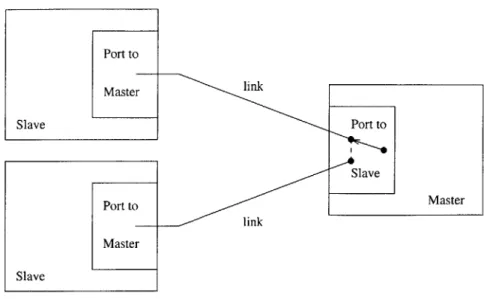
The DAQ is a distributed system. The basic building blocks of this system are the single processor computers or modules discussed in chapter 2. Modules communicate to each other via ports and links. Ports are simply the hardware used for communica-tion, and each module has a fixed number of these. Links are the wires that connect modules, and so there is one link for every pair of connected modules. To communi-cate with a neighboring module, a module selects a port, connects that port to the appropriate link, and then initiates the transmission (Figure 3-1). Most modules in this system have limited memory, and so we impose a constraint that the communi-cation protocols require a small fixed amount of memory. Furthermore, unless the module has ample memory (i.e. represents ground or an MDC), the module should only be locally aware of his surroundings, or equivalently, from the state of a module, we should only be able to derive the immediate neighbors of the module.
The DAQ system design defines the basic structure of intermodule relationships, or how modules communicate with each other. Communication in the DAQ system has a layered architecture design [3, 15, 13]. Each layer accomplishes a set of functions and is transparent to other layers. There are three layers. The physical layer is the AMSWIRE protocol [4] responsible for transmission and reception of actual bytes of data. The data link layer captures the protocols modules use to exchange messages (Section 3.1). The application layer defines the sequence of messages deployed to accomplish the high-level tasks of the DAQ system (Section 3.2).
Port to MasterM Slave Port to Slave Port to Master Master Slave
Figure 3-1: Ports and links
3.1
Relationships
The data link layer communication between modules adheres to one of two sets of protocols, the master-slave relationship or the girlfriend-boyfriend relationship. The master-slave relationship optimizes communication in the case of fast, reliable links between modules of low memory. The girlfriend-boyfriend relationship optimizes communication in the case of slow, unreliable links between modules of moderately
high memory.
3.1.1
Masters and Slaves
Modules are arranged in a master-slave hierarchy. This system is represented by a directed graph which may evolve with time (Figure 3-2). Each node is a module. Each arrow is a master-slave relationship drawn from the master module to the slave module. Notice if there is a path from A to D in the directed system graph, then A can command D by appropriately commanding the intermediary modules (B or C in the example in the figure). In this case we call D a subslave of A. As shown in the figure, a master may have multiple slaves and a slave may have multiple masters. In fact, we use this generalization in the DAQ system in order to implement redundancy.
A
MDC
B c TDCs
D E F G IDCs
H I J K L M N 0 FEEs
Figure 3-2: Directed system graph
However, in this study we concentrate on the case when slaves have just one master although all algorithms presented extended to the general case.
In general, we would like the master module to have complete control over the slave module. The slave module, on the other hand, should only interact with the master module when his service is requested. This means every piece of transmitted information needs two messages, one from the master module to the slave module requesting a service and one from the slave module to the master module servicing the request. This simple model of communication is ideal for our purposes. It is easy to implement and requires minimal memory. In particular, there is no need to queue messages, and there is no need to store them for retransmission.
More specifically, we define master and slave protocols. To state these protocols, we introduce some definitions.
9 reply: A message from a slave to a master
* handle: A reply is considered handled when it is sent (slave)/received (master) " service: A request is considered serviced when the reply it generated has been
handled
Now we can define the protocols.
* Master protocol The master promises to pass a request to a slave only after
the previous request to that slave has been serviced.
" Slave protocol The slave promises to generate a reply only in response to the
most recent request in the slave's view, and only if that request is unserviced.
Actually, these protocols are not strong enough for us. The main problem is that messages that are sent are not necessarily received. Although in fact it is highly unlikely that a sent message will be simply lost in transmission, it is quite possible that a message gets corrupted in memory causing the module to enter a state in which he assumes he never received that message. This allows for two probable scenarios which will cause infinite delay in the system. In one scenario, the slave sends a reply which the master never receives. In the other scenario, the master sends a request which the slave never receives. For example, say a master sends a slave a request and after the slave receives the request, some external effect such as a latch-up corrupts the slave's memory. As this memory corruption sends the slave into an undetermined state, it is possible that the slave will no longer realize there is a pending request. The master, according to the protocol, should wait indefinitely for the slave to reply. Yet the slave will not reply as he perceives no pending request. The slave (or at least that master-slave link) will be inaccessible forever more even though the slave is healthy. Although it is never possible to completely advert an attack from a malicious module with unbounded power, we can try to avoid some plausible error scenarios like the one described above. To accomplish this, we introduce the notion of a timeout.
Master Slave
send request send request
send reply timeout send reply
receive reply
Request is serviced twice in master's view. Request is never serviced in master's view.
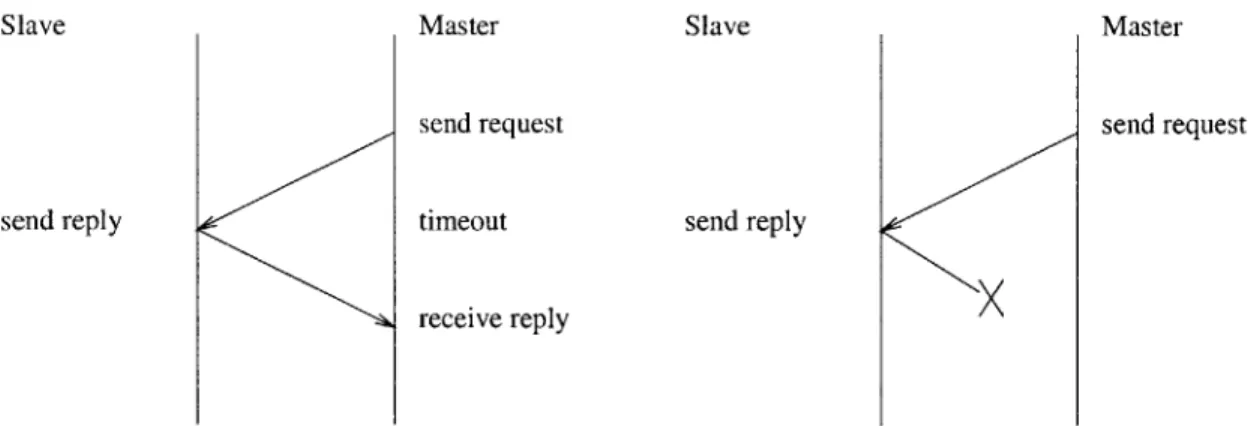
Figure 3-3: Communication errors
request to his slave. If the slave does not respond before the alarm goes off, the master considers his request as serviced and continues with the protocol. More formally, we need to modify our definition of service.
* service: A request is considered serviced when the reply it generated has been handled or it has caused a timeout
There are still some problems with our protocols. The problems stem from our definitions of handle and service. As a slave is never informed of a timeout in his master, it is conceivable that some request has been serviced in the master's view but not in the slave's view. This could cause a request to be serviced twice in the master's view (Figure 3-3). Similarly, as sent messages are not necessarily received, it is conceivable that some reply has been handled (and thus the request has been serviced) in the slave's view but not in the master's view. This could cause a request to never be serviced in the master's view (Figure 3-3).
There are various ways to deal with the problems of loss, reordering, and duplica-tion of messages. A common approach is to introduce unique identificaduplica-tion tags for every message. However, this approach adds additional memory requirements and complexity. Simple protocols usually assume messages have unbounded length [11]. Bounded-message length protocols are highly complex
[1].
In fact, it can be shownthat there are no "efficient" protocols that tolerate loss and reordering in the com-munication [1].
Luckily, our situation is less complex. In particular, we need to tolerate loss, but not reordering or duplication of messages. Our solution is to ignore these problems. In fact, these problems are not very probable if we choose our design and parameters well. If a slave thinks a request has been handled and the master does not, this request will cause a timeout in the master and the master may decide to reissue the request. If we design our request issuing routines with this scenario in mind (i.e. a timeout does not imply the slave did not perform the actions in the request), we can assure ourselves that this problem will not harm us. We can also avoid the situation in which a master thinks a request has been handled and the slave does not. We just need to pick the timeout constant large enough to guarantee that a reply from a healthy slave will be received before the alarm goes off.
3.1.2
Girlfriends and Boyfriends
The master-slave relationship works very well if the connection from the master to the slave is fast and reliable. However, in our DAQ system, the link from the ulti-mate master, ground, to her immediate slaves, the MDCs, had large delay and down time. Furthermore, ground has virtually infinite resources, making the stringent re-quirements governing the design of the master-slave relationship unnecessary in this case.
There is some information, such as the system status, that must be constantly updated in the ground module. However, this information resides in the MDCs. If the ground-MDC relationship was a strict master-slave relationship, the ground would have to request this information of the MDCs regularly, wasting half the precious bandwidth with a predictable request.
We avoid this problem by defining a girlfriend-boyfriend relationship in which the MDCs simply send certain pre-determined information, called flowers, to the ground. The girlfriend (ground) doesn't request the flowers but the boyfriend (MDC) sends them anyway. All conversations initiated by the girlfriend work according to the
master-slave relationship with the girlfriend as the master, and the girlfriend doesn't consider flowers as an appropriate reply to any of her requests, although she does expect them.
The girlfriend's implementation of a girlfriend-boyfriend relationship is simple. As boyfriends send flowers at unpredictable moments, the girlfriend just needs to implement a queue for boyfriend messages. Then the girlfriend can process all the messages in the queue sequentially - it does not matter if the message is a flower or a reply. The boyfriend's implementation of a girlfriend-boyfriend relationship is straightforward as well. The boyfriend just runs some routines that collect and send the girlfriend flowers periodically. We will see an example of this in Section 3.2.1.
3.1.3
Messages
Messages must conform to a particular format in order for our system to interpret them. There are two basic parts to any message - the header and the data. The header is of fixed length and contains vital information concerning the type of message and perhaps some error checking bits. The data is of variable length and contains everything else, that is, the essentials of what is being communicated.
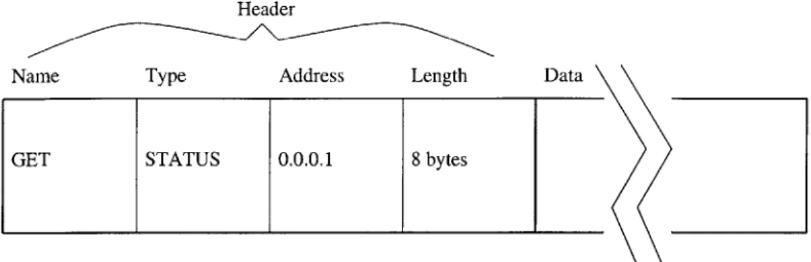
The format of a message is dependent on whether it is a request or a reply. Requests come in two basic flavors - those that change the state of the slave and those that do not. We refer to these requests as set and get requests respectively. The header of a request indicates whether it is a set or get request in the name field. The header also indicates the type of request and the length of the request. The name and type fields help a slave determine the appropriate response. The length field tells the slave how much information to read from the data field and is necessitated by the implementation of the underlying communication ports. The data field of a request is very general and can be designed to contain anything. Typically, the data field of a get request might contain additional information about what state the master wants the slave to read. The data field of a set request might contain the information the master wants the slave to write.
Header
Name Type Address Length
GET STATUS 0.0.0.1 8 bytes
Data \
Figure 3-4: Example request
this case the above description of a request header is sufficient. In general, though, a master may want to command a subslave. For example, say a position aware module
A is a master of module B and module B is a master of module D (Figure 3-2). That
is, D is a subslave of A. Then our design enables A to command D by requesting
B to send a particular request to D. This process can be viewed as two separate
direct communications. However, to ease implementation and improve efficiency, it would help to introduce an addressing scheme and allow A to use B as a kind of router for D. To implement this solution, we add an address field to the request header. B considers the address field when servicing requests and handling replies.
A stores the address of D and every other subslave he may wish to command in his
memory. Notice this address field is only useful if there are position aware modules in our system, and these position aware modules can only use this field to address their subslaves.
As an example of a request, consider the case in which a master wants to know the status of a slave. To do this, the master should send the slave a GET STATUS request (Figure 3-4).
There is still a small problem with our solution. Say in the above example D is dead. Then the request to D will generate a timeout in B. After this timeout, B will
send a reply to A. In order to avoid having A's request serviced twice, A's timeout
his position from the length of his timeout. We can fix this problem by having the timeout parameter be a function of the message, but this adds a barely used field to our message format. What we actually do is force B to suppress his reply if he experiences a timeout. Then A's request will be serviced just once. But this causes another problem. As we insist all requests have the same timeout length, and as A starts his alarm before B, A will experience a timeout signal before B. Thus, A's request will be serviced in A's view and not in B's view. Now A may send B a second request, violating the master protocol in B's view. In our analysis, we do not address this problem, but we recommend the final implementation adopt a solution where each module has a different timeout length. As our actual system has just four levels of masters and slaves, this varied timeout length does not cause additional memory requirements.
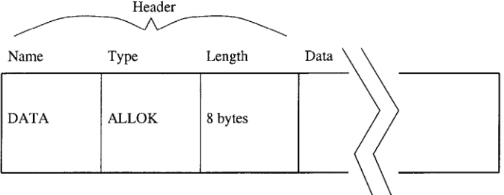
In general, replies are much simpler than requests. A reply is only ever generated in response to the most recent request. Therefore, a master always knows what an incoming reply should contain and where it originated. In essence, the only necessary header field is the length field. However, our implementation retains the name and type fields in the reply header in order to aid the master in interpreting the reply. We use three reply names, FAILURE, ABORT, and DATA. The FAILURE name is used to indicate that the slave was incapable of servicing the master request due to some error in the slave. The ABORT name is used to indicate the slave did not understand the master request (perhaps it got corrupted in transmission). The DATA name is used to indicate everything else. The type field varies depending on the reply and request. The ERROR type is always used in conjunction with the FAILURE and ABORT names. A common type is the ALLOK type (Figure 3-5). This type is typically generated in response to a set request.
It is conceivable that a master may want to make the same request of all his slaves and subslaves at one time (i.e. broadcast a request). A master can accomplish this
by sending a request to every subslave if he uses the appropriate addressing scheme.
Although this may seem like a reasonable solution, there are two major problems with it. First, it assumes any module that wants to broadcast a request is position
Header
Name Type Length
DATA ALLOK 8 bytes
Data \
Figure 3-5: Example reply
aware. Second, it generates a lot of traffic on the network. We solve these problems
by introducing another address called a STAR address and a state variable called a
broadcast request list. When a module receives a STAR request, he will service this request himself as well as request every slave on his broadcast request list to service this request. If these broadcast request lists are disjoint and their union covers all subslaves, the request will reach every subslave and will traverse every link in the network exactly once.
We must be careful when we design replies to a STAR request. Our protocols imply that each request should generate exactly one reply. Say a module B with master A and slave C receives a STAR request from A. Both B and C will service this request and generate replies. As the request originated from A, C's reply should reach A. However, B should also reply to A. As A can only receive one reply to his request, B must intercept C's reply, package it with his own reply, and send this combined reply to C. To accommodate this situation, we introduce a new reply type called BROAD. When a module receives a STAR request, he services the request, sends the request to all his slaves, waits for all the slaves to service the request, and then packages all generated replies in the data field of a BROAD reply.
3.2
Tasks
Within the confines of this system, modules can coordinate to complete tasks. Mas-ters have one routine per task that issues requests and handles corresponding replies. Slaves have a routine that services requests. The request issuing and reply handling routines for a specific task are implemented in a distributed algorithm called a
Pro-gram K (for historical reasons1). This algorithm can be thought of as a state machine,
performing actions in state transitions and relinquishing control of the module after every state transition. The request servicing routine is implemented in a massive switch statement with a case for every plausible request. The module software runs the request servicing routine and each Program K sequentially in an infinite loop.
This design is highly flexible and scalable. To implement a new task, an engineer simply needs to write a Program K and add some cases to the request servicing rou-tine. So long as this new Program K relinquishes control periodically, implements a stop state, and is not malicious, the system should continue to function healthily. For a Program K to relinquish control periodically, it just needs the actions in the transitions to take finite time and be autonomous. To implement a stop state, the Program K needs to have a transition to a stop state which becomes possible peri-odically. It is hard to guarantee a Program K is not malicious, for it is not clear what conditions must hold for this to be true. Instead, we suggest a guideline that must be followed - the module must not violate the master protocol. For example, if transitions to a state A issue requests, we can not allow any transitions from A to the
STOP state. If the master took such a transition, he would never notice the servicing
of his request. As a link is only freed when a request is serviced, the corresponding link would remain busy indefinitely.
In general, distributed algorithms are difficult to define and verify [9]. As
exam-'When Alexei Lebedev was sick in the hospital with lung cancer, everyone thought he would die. But, thanks to some innovative treatment, he miraculously survived his devastating disease. The doctors published the details of the case in the prominent medical journals of the time. In order to preserve the anonymity of the patient in these reports, they referred to him by the pseudonym Patient L. In honor of this tradition of secrecy, we invented the term Program K to reference a member of the set of module tasks.
ples, we discuss two algorithms - system monitoring and event building - and verify them informally.
3.2.1
System Monitoring
The system monitoring task gives the ultimate master (i.e. the user) enough infor-mation to manually keep the system alive. Each module contains a status variable indicating the health of the module and the quality of the data it collects. The sys-tem promises to always eventually alert the user about the health of each module (sooner rather than later). Some ultimate position aware master module periodically and sequentially request the status of each module and report the result to the user. This periodic sequential requesting will accomplish our stated goal, and it does so with just a constant load on the system. In contrast, a periodic broadcast request for status, although easier to implement, would cause surges in network traffic slowing down the more important task of event building.
To implement system monitoring, we need to introduce some new variables and request types. The new variables help us control the system monitoring task. The boolean variable runStat, depending on its value, forces the Program K state machine to enter the START or STOP state. A list of modules, the monitor list, contains information regarding all this module's subslaves. For each subslave on the list, the monitor list indicates whether this module should request status from that subslave. The monitor list sequentially enumerates those subslaves for which this module should request status.
To obtain the status information from the modules, we need a GET STATUS request (Figure 3-4). This request asks the module to reply with his status. Two other requests help the user control the system monitoring program. The SET SYSMON request asks the module to start or stop the system monitoring task. The SET
MONLIST request edits the module's monitor list.
For every new request type, we must add a case to the request servicing routine of the appropriate slaves. To service a GET STATUS request, a slave sends a DATA
SEND WAIT
STOP
Figure 3-6: System monitoring Program K state diagram
a slave forces his system monitoring Program K to enter the START or STOP state according to the request by setting runStat to true or false respectively. The slave replies with a DATA ALLOK reply. To service a SET MONLIST request, a slave sets the state of his monitor list according to the instructions in the data field of the request and again responds with a DATA ALLOK reply.
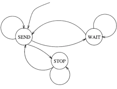
The system monitoring Program K has just three states - the SEND state (which
is also the START state), the WAIT state, and the STOP state (Figure 3-6, Table 3.1).
From the SEND state, the module requests the status of the next slave. From the
WAIT state, the module waits for the request to be serviced and then transmits the reply to the user. From the STOP state, the module simply ends the system
monitoring task.
To argue correctness of this implementation, we must show that it accomplishes the goal of the system monitoring task while maintaining the conditions of a Program K. Clearly, unless the user forces the system into the STOP state or empties the
monitor list, he will always eventually receive status or a timeout from the modules in the monitor list. In fact, he will have to wait at most one timeout length between status reports.
Transition Pre - condition Action/Post - condition
SEND - WAIT runStat is set and monitor list send GET STATUS to next
is not empty slave in monitor list enumera-tion
SEND -+ SEND monitor list is empty none
SEND -- STOP runStat is not set none
WAIT -+ SEND request was serviced inform user of reply
WAIT -> WAIT request was not serviced none
STOP -+ SEND runStat is set set monitor list to request
sta-tus of all subslaves
STOP - STOP runStat is not set none
Table 3.1: System monitoring Program K transitions
periodically, implements a stop state, and is not malicious. The state transitions take finite time, and we can relinquish control after every transition while maintaining correctness because the actions of the transitions are autonomous. Once the runStat variable is set to false, we will eventually reach the STOP state. We will have to wait at most the length of one timeout. Finally, our Program K appears to not be malicious for it does not violate the master protocol. We only send one request to each slave before receiving a reply, and there is no transition from the WAIT state to the STOP state.
In the actual DAQ system, the ultimate position aware master modules that will run the system monitoring task are the MDCs. The user which will view the system monitoring data are the scientists on ground. The MDCs send this data to ground in the form of flower messages in a girlfriend-boyfriend relationship (see Section 3.1.2).
3.2.2
Event Building
The main purpose of the DAQ system is to build events from event fragments in a consistent manner. In our distributed system model, event fragments are simply pieces of information created in some subset of m modules
{fi}.
In the real DAQ system, these modules are simply the FEEs. Each module in this set creates fragments of event ej sequentially at varying rates. Say fi(ej) is the event fragment createdMDC r r(e)= {fl, f2,f3, f4, f5, f6, f7, f8, f9, fl0, f11, f12}
TDCs mn m m2(e) = {f7, f8, f9, fl0, f11, fl2}
IDCs s1 s2 s3 s4 s4(e)= {fl0, fl1, fH2}
FEEs fl f2f3 f4 f5 f6 f7 f8 f9 fi fI fi
Figure 3-7: Event building
by module
fi
for event ej. The event building task is to collect the sets or eventsej = {fi(ej), ... , fm(ej)} in one single module and always eventually report these sets
to the user. Furthermore, should some some fi be broken or unreachable, we would like to report partial events without losing consistency.
We accomplish this by having each module request event subsets from its slaves in a first-in-first-out (FIFO) manner (Figure 3-7). In other words, if a module m
has slaves si,. . ., s, then m collects from its slaves a subset of event ej, m(ej) =
Un isi(ej). If we arrange our directed system graph in a tree structure, at the root
node r, r(ej) = ej. From this point on, we will refer to any subset of an event as an
event fragment.
We must implement this task subject to low memory constraints and unreliable modules. In particular, we assume each module has a queue of fixed depth onto which
it can push any subset of an event. We call this storage the event queue. We also have storage for the event fragments currently being collected (the current event) and
a list of slaves from which to request events (the request list). The request list will be
maintained such that the slaves on the list are working and have consistent queues. In addition, we need a timer (the event timer) to force us to not spend too much time collecting any single event. This will prevent a partially broken slave from hanging
the system.
To get events from slaves, we will need to create a request for reading events. This request should cause the slave to return to the master the least recent event that the master has not seen yet and delete the last event returned, and we name it the GET EVENTPOPPEEK request due to the FIFO queue implementation of event storage. In case of errors, in order to maintain consistency, we also need to create a request that will cause the slave to return to the master the event he last returned. We name this request the GET EVENTPEEK request. To implement both of these with minimal memory usage, we store the event that may need to be retransmitted on the event queue. Upon a GET EVENTPOPPEEK request, a slave pops and then returns the peek of his event queue (notice this changes the state of the slave, contrary to our claim about get requests). Upon a GET EVENTPEEK request, a slave just returns the peek of his event queue. Sometimes, the slave's queue may be empty. In these cases, we have another reply, DATA NYETA, which indicates no event is available for transmission.
The event building Program K first asks all slaves for an event fragment. Then it waits for some replies. It uses information coded in the event fragment to check consistency of the replies. If some slave returns an inconsistent event or is broken (the request generated a FAILURE ERROR reply), the Program K stops requesting event fragments from that slave. For the slaves that reply DATA NYETA, the Program K asks for the event again. It continues in this manner until either all the slaves in the request list have replied, or the event timer has expired. The Program K again modifies the request list to contain just those slaves that replied with a consistent event fragment. In this way, consistency of the event queues will not be violated by a slave that did not receive the event fragment before the event timer expired. Then the Program K waits for a free spot on the event queue, pushes the current event onto the event queue, and begins again. Note the Program K must use the proper request, GET EVENTPOPPEEK or GET EVENTPEEK, for each event request.
Should the Program K be requested to stop during this process, it must first complete the current event fragment. This will take at most the time of the event
POST MA
STOP
PUSH WAIT
Figure 3-8: Event building Program K state diagram
timer plus the time of a timeout. Then the Program K makes note of its current state so that when it is restarted, it will perform the correct action.
To implement this Program K, we use five states - the POST state (which is also the START state), the MAKE state, the PUSH state, the WAIT state, and the STOP state (Figure 3-8, Table 3.2). In the POST state, the module transmits the
initial event fragment requests. In the MAKE state, the module collates the returned event fragments. In the PUSH state, the module stores the current event on the event
queue. The WAIT state is used when the event timer expires before the event is built. In the WAIT state, the Program K waits for all pending requests to be serviced.
The most challenging aspect of the event building task is to maintain consistency
of events. We can informally argue that our implementation does in fact maintain consistency. We study just one master m and his set of n slaves {si}. Say slave si generates fragment si(ej) of event ej. We would like to prove the set of fragments on the master's event queue are consistent. That is, si(ej) is in the same set as Sk(eI) if
Transition Pre - condition Action/Post - condition
POST -+ MAKE request list is not empty and request event of all slaves in
re-stopBuild is not set quest list
POST - POST request list is empty and stop- store appropriate request for
Build is not set each slave to maintain consis-tency
POST -+ STOP stopBuild is set none
MAKE -- PUSH all slaves in request list replied set request list to slaves that
with event replied; store event fragments in current event
MAKE -+ MAKE event timer did not expire and re-request event from slaves
some slave in request list has who have serviced last re-not replied with event quest and have not returned an event; store event fragments in current event
MAKE -+ WAIT event timer expired store event fragments in
cur-rent event
WAIT -+ PUSH all requests have been serviced set request list to slaves that
replied with an event fragment; store event fragments in cur-rent event
WAIT -+ WAIT some request has not been ser- store event fragments in
cur-viced rent event
PUSH -+ POST there is room in event queue push event onto event queue
and stopBuild is not set
PUSH -+ PUSH there is no room in event queue none
stopBuild is not set
PUSH -+ STOP stopBuild is set store appropriate request for each slave to maintain consis-tency
STOP - STOP stopBuild is set none
STOP - POST stopBuild is not set and last none
state was POST
STOP -+ PUSH stopBuild is not set and last none
state was PUSH
and only if
j
= 1. We prove this by induction, adding the stipulation that the slaves are mutually consistent once event ej is built, that is when the Program K enters thePUSH state with the current event ej all slaves si in the request list have si(ej) in
the peek of the event queue.
First consider the situation in which no event requests have been made. For simplicity, we assume all slaves are in the event request list and are functioning normally (i.e. receive events sequentially). Initially, every slave's queue is either empty or contains a fragment of event el. The master starts the event building task in the POST state. He sends a GET EVENTPEEK request to every slave. Then he waits for replies in the MAKE state. For each slave si, there are three possible outcomes - a DATA EVENT reply, a DATA NYETA reply, or a timeout. If a slave replies with an event fragment, the fragment will be s (ei) as the event queue is FIFO and events are received sequentially. The peek of the event queue is si(ei) as required. If the slave replies with a DATA NYETA reply, the master will resend the
GET EVENTPEEK request, and by the previous argument the inductive hypothesis
still holds if the slave eventually replies with an event. If the slave never replies with an event (i.e. the event timer expired before the slave's event queue got filled), then the slave is removed from the request list in the WAIT state and the inductive hypothesis holds. If there is a timeout, the master will remove si from his request list and again the inductive hypothesis holds. This shows that the first event is received consistently by the time the master's event building program reaches the PUSH state. Suppose the master has received all events up to event ej consistently and the slaves are mutually consistent. Now the master enters the POST state and sends a
GET EVENTPOPPEEK request to every slave. This pops event fragment si(ej) off
each slave's event queue and causes the slave to send the peek of the event queue. As events are received sequentially, the peek of the event queue will either be si(ej+,) or empty. If the slave replies with an event fragment, it will be the correct event frag-ment, si(ej+), and so part of event ej+i has been received consistently. If the slave replied with a DATA NYETA reply, the master sends the request GET EVENT-PEEK. As this situation is analogous to the one in the last paragraph, the same