Conceptual Engineering Designs for a Mechanical Shutter, a Medical
Room Door, and a Water Shutter for a Fission Converter-Based Boron
Neutron Capture Therapy Medical Facility
ByJerry R. White
B.S., Mechanical Engineering University of Texas at Austin (1996)
Submitted to the Department of Mechanical Engineering on May 8, 1999 ir Partial Fulfillment of the Requirements for the Degree of
MASTER OF SCIENCE IN MECHANICAL ENGINEERING
at the
MASSACHUSETTS INSTITUTE OF TECHNOLOGY
MASSACH
June 1999
Copyright @ 1999 Massachusetts Institute of Technology
All Rights Reserved
Signature of Author:
Department
Certified by:
of Mechanical Engineering May 8, 1999
1 f sor Otto K. Harling Thesis Advisor
6'
Professor Peter Griffith, " Thesis Advisor
Accepted by:
Professor Ain A. Sonin Chairman, Department Committee on Graduate Students
"Conceptual Engineering Designs for a Mechanical
Shutter, a Medical Room Door, and a Water Shutter for a
Fission Converter-Based Boron Neutron Capture
Therapy Medical Facility"
by
Jerry R. White
Submitted to the Department of Mechanical Engineering on May 8,
1999 in Partial Fulfillment of the Requirements for the Degree of
Master of Science in Mechanical Engineering
Abstract
The conceptual designs for a mechanical shutter, a medical room door, and, a water shutter for use in a new fission converter-based boron neutron capture therapy medical facility were developed. In the design of the
mechanical shutter and the medical room door, several alternatives were introduced. Design methodology and engineering judgment yielded the overall best -- conceptually speaking -- alternatives to pursue. These were a
horizontally-moving mechanical shutter (perpendicular to the fission converter beamline) and a sliding medical room door (parallel to the fission converter beamline). For the water shutter, engineering judgment and simplification were used to scale back the water shutter design from the initial two-tank idea to the final one-tank design.
Thesis Supervisor: Otto K. Harling Title: Professor of Nuclear Engineering
Thesis Supervisor: Peter Griffith
Acknowledgments
I would like to thank my thesis advisor, Professor Harling for his guidance,
advice, and understanding throughout this work. I would also like to thank
Professor Harling for the oppurtunity to participate and help during the patient
irradiation treatments. I am also thankful to my other thesis advisor, Professor
Griffith, Professor of Mechanical Engineering, for his insight and guidance
throughout this timely project.
I appreciate the help I received from the staff working in the Nuclear
Reactor Lab, including: Ed Block, John DiCiaccio, Gordon Kohse, Fred
McWilliams, Paul Menadier, Tom Newton, Yakov Ostrovsky, and Pete Stahle.
I would also like to acknowledge the support I was given from the
students I was privileged to work with: Cynthia Chuang, Indra Djutrisno, Tim
Goorley, Stead Kiger, Michelle Ledesma, and Kent Riley.
Lastly, I am especially grateful to my parents, without whom I could not
Table of Contents
Abstract
2
Acknowledgments
3
Table of Contents
4
List of Figures
7
List of Tables
10
Chapter 1
11
Introduction
11
1.1 Boron Neutron Capture Therapy (BNCT)
11
1.2 Fission Converter Beam (FCB)
12
1.3 Thesis Objective
16
Chapter 2
17
FCB Shutters
2.1 Introduction
17
2.2 Fast Shutter Function
19
2.3 Fast Shutter Design Goals and Requirements
20
2.4 Horizontal Fast Shutter Design Choice
21
2.5 Horizontal Shutter - Conceptual Design
25
Chapter 3
30
Medical Room Door
3.1 Introduction
30
3.2 Medical Room Door Function
31
3.3 Medical Room Door Design Goals and Requirements
32
3.4 Medical Room Door Options
33
3.5 Chamfered Medical Room Door Design Choice
39
3.6 Chamfered Door - Conceptual Design
40
Chapter 4
43
Water Shutter
4.1 Introduction
43
4.2 Design Goals and Requirements
45
4.3 Fluidic Design
46
Summary and Suggestions for Future Work
5.1 Summary
47
5.2 Suggestions for Future Work
48
5.2.1 Mechanical Shutter Suggestions
49
5.2.2 Medical Room Door Suggestions
53
5.2.3 Water Shutter Suggestions
54
References
55
Appendices
58
Appendix A Fast Shutter Alternative Designs
58
A. 1 Vertical Fast Shutter 59
A.2 Circular Fast Shutters 68
A.3 Slanted Fast Shutter 76
Appendix B Fast Shutter Design Methodology, Decision Criteria,
and Decision Matrix
80
B.1 Fast Shutter Design Methodology 81
B.2 Fast Shutter Decision Criteria 83
B.3 Fast Shutter Decision Matrix 89
Appendix C Horizontal Shutter Stresses and Deflections
98
D.3 Parallel-to-Beam Sliding Door D.4 Slanted Sliding Door
D.5 Transverse-to-Beam Sliding Door
Appendix E Water Shutter Fluid Circuit Analysis
List of Figures
Chapter 1
Introduction
Figure 1.1 Block Diagram of the FCB System
Figure 1.2 Reactor and FCB Components (Courtesy of W.S. Kiger)
Chapter 2
FCB Shutters
Figure 2.1. Horizontal Shutter
Figure 2.2. Shutter Support and Shield Blocks Figure 2.3. Horizontal Shutter in the Open Position Figure 2.4. Shutter Delimiter and Removable Collimators
Chapter 3
124 127 131134
11
13 1517
22 26 28 2930
Medical Room Door
Figure 3.1. Plan View of the New Medical Room Layout (Courtesy of M.N.
Ledesma) 38
Figure 3.2. Chamfered Sliding Door -- Plan View, Closed Position 41
Figure 3.3. Chamfered Sliding Door - Plan View, Open Position 42
Chapter 4
Water Shutter
Figure 4.1. Water Shutter Fluid Circuit
Chapter 5
Summary
Figure 5.1. Figure 5.2.Appendices
43
4447
and Suggestions for Future Work
Isometric View of Sectioned Medical Room Isometric View of Extended Shutter
Appendix A.1
Figure A.1.1. Open Fast Shutter inside Cave. Figure A.1.2. Closed Fast Shutter inside Cave. Figure A.1.3. Closed Fast Shutter outside Cave.
51 52
58
58
61 62 64Appendix A.2
68
Figure A.2.1. Support Wheel Circular Shutter 70 Figure A.2.2. Center Bearing Circular Shutter 71Appendix A.3
76
Figure A.3.1. 18 Degree Slanted Shutter 79
Appendix B.2
83
Figure B.2.1. Sections of Reactor Floor Steel Reinforcement Bars 86 Figure B.2.2. Floor Hole Showing the Bars Needing to be Cut 87
Appendix D.1
109
Figure D.1.1. One Hinged and Swinging Door 111
Appendix D.2
121
Figure D.2.1. Vertically Moving Door 123
Appendix D.3
124
Figure D.3.1. Parallel-to-Beam Sliding Door 126
Appendix D.4
127
Figure D.4.1. Slanted Sliding Door -- Plan View 129
Figure D.4.2. Slanted Sliding Door -- Isometric View 130
Appendix D.5
131
List of Tables
Chapter 3
30
Medical Room Door
Table 3.1 Properties of Single Composition Door Options (Courtesy of M.N.
Ledesma) 34
Table 3.2 Properties of Door Options -- Combination of Shielding Materials
(Courtesy of M.N. Ledesma) 35
Table 3.3 Estimated Costs of Door Options -- Both Single Composition and
Chapter 1
Introduction
1.1 Boron Neutron Capture Therapy (BNCT)
Boron Neutron Capture Therapy (BNCT) has been around since 1936
when it was suggested by Gordon L. Locher at the Franklin Institute in
Swarthmore, Pa. (Barth, et al, 1990). Clinical studies of brain cancer
(glioblastoma multiforme) began in the 1950s; however, some patients died due
to excessive radiation to microvasculature. Subsequently, studies in the USA
tapered off and stopped in the early 1960s.
Nevertheless, with recent advancements in the development of effective
boron compounds, improved neutron beams, and dosimetry, interest in BNCT
has increased for the possible treatment of the glioblastoma multiforme and
metastatic melanoma types of cancer.
BNCT involves the infusion of a boron-10 (B10) containing compound into
the patient. This 310 compound has been engineered such that it concentrates
preferentially within the patient's tumor cells. The area of the tumor is then
electron-volt (eV) to 10 keV). These neutrons are thermalized (thermal neutrons have
energies around .025 eV) as they pass through bone and tissue to arrive at the
cancerous cells. The 310 atoms, having a high cross-section for the absorption
of thermal neutrons, then undergo Bl(n,a)Li7 reactions whereby the thermal
neutron captured by the 310 atom excites the 310 to an unstable B1 state. This
B11 atom then decays, or 'fissions,' releasing a Lithium-7 ion (Li7), an alpha
particle and 2.3 MeV of kinetic energy. The highly energized Li7 and alpha
particles deposit all of their energy within a range of less than 13 tm (the
approximate diameter of a normal cell), thereby minimizing the potential for
adjacent healthy tissues to be deleteriously affected.
The Nuclear Reactor Lab (NRL) at MIT is currently funded by the
Department of Energy in order to construct a facility whereby MIT and the Beth
Israel-Deaconess Hospital can perform BNCT clinical trials with an improved
epithermal neutron irradiation facility. This new facility, called the fission
converter beam (FCB), will provide medical and nuclear engineering personnel a
state of the art setting and a cleaner, more intense neutron beam than is
currently employed.
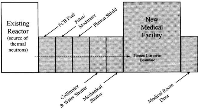
The main components of the fission converter beam facility are shown
schematically in Figure 1.1. These components are usually massive pieces of
equipment (on the order of several tons apiece).
Existing
Reactor
(source of thermal neutrons) 4~ ~ 4~O ... ... .... ... : ...... ... ... .. ... ... ... ... ... ... ... % ......... ... .... %%.... .. ... ... % ...... ... .. ...... ... ... ... ...........
%%.%
...
...
%
lmfi
...
...
%%
...
...
...
... ...
... ..
...
...
.
...
...
...
.... ...
...
.
..
...
...
...
...
..
...
M e&
...
...
...
%.%
.
...
...
...
...
%%.%
...
...
.
...
...
...
...
...
..
...
X :Mz.*
...
...
...
...
%
...
...
... ... ... ... ... ---... ... ... ... ... ... ... ... ... ... ... ... ... .. ... ... .... ... ..... ...... ......... ... ... ... ... .... ... ... ... ... ... ... ... ... X... ... ... .. . ... ... ... .... ... * ...*-,** ... ... ... % .. ... ... ...... ... ... ... .. ... ... ... ... ... ... ... ... ... ... ... .... ... .... ... ... % ... ... .% ... : . ... ... ... . . ... ... ... .. ... ... ... . ... ... .. ... ... ... '*'*****'*'**** ... ... . .... ... ... .. ...V.. .. . . ... ... % .% . ... ... ... ... ... . .......... ... ... ... ... %-.-.%%-.% ... ... ... .... .... ... . ... ... ... ... ... ...... %. . .... ... .... ... .. ... ... .... ... . ... ... ... ... ... .% ... . ... : ... ... ... ... .. .. ... ... ... ... ... ... ... .... . ... ... ... ... ... * .... ... ... ... % ... ... . ... .... ... ... ... ... % ... .... ... ... ... ... ... ... ... ... ... ... ... ... .... ... ... % ... ... .......... ...... ... -- - . .. .. :.- ... %% ... ... ... % ... ... ... ... ... ... .... . ... . ... : .. ... ... ... .% '****'***,*" ... " **, - -... ...... % ... ,*,,,,,*,,-*,* ...Figure 1.1. Block Diagram of the FCB system.
When the FCB system is in operation, most neutrons from the reactor,
upon entering the FCB fuel elements, interact with Uranium-235 (U23 5) atoms
and each reaction produces 2 to 3 more neutrons. With many of these reactions
occurring each second (approximately 2*1016 per second) a source of neutrons
for the patient treatment beam in the medical room is established. On their way
to the patient, the neutrons are partially moderated, filtered, and collimated. I K.*-*-*-*,.'..'....*...'..'....,...-:--.E.-:--.-...-:--...-:--..-...-:.-.-.-:--.-.N.----.---.---:.---.-.--.--.-.-:-.---- g--..,; .- .- .- .. ... W.. .. .- .--- .. ...-...... ZZ N
AN
<4N
C*I
V00
When they pass through the filter/moderator, the neutrons, which are still 'fast'
(neutrons in the energy range of 100 keV to 10 MeV) are slowed down to the
epithermal range; most of the remaining fast neutrons are scattered out of the
beamline. In the photon shield, harmful gamma rays (photons) are heavily
attenuated. As a result, the photon shield, in front of the collimator, removes
most of the unwanted gamma rays, leaving a neutron beam with low photon
contamination. The neutrons are then collimated, or 'funnelled,' in the collimator
module, producing a compact, high-intensity beam. Inside the collimator module
is an aluminum tank, which can be filled with water. This tank is known as the
water shutter. It is emptied to allow for neutron beam transmission; filled to help
attenuate the beam. Following the collimator module, the mechanical shutter
then acts as a heavy, movable slab, which controls the supply of neutrons to the
patient. The medical room, or shielded irradiation room, is where the patient is
placed to receive an irradiation treatment, having entered via the medical room
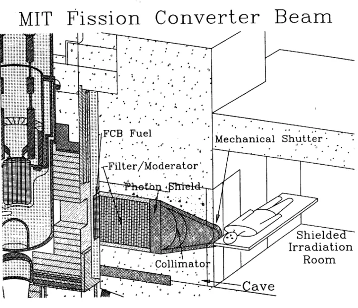
door; see Figure 1.2, a simplified isometric figure of the reactor and the FCB
components.
Staff in the Nuclear Reactor Laboratory (NRL) and the Nuclear
Engineering Department (NED) are designing the FCB facility and students from
the Mechanical Engineering (ME) Department have been assisting in the design
of the mechanical shutter, the FCB cooling system, and the door to the medical
MIT Fission
Converter
Beam
- 4 -FCB Fuel -Mechanical ShutterFilter/Moderator
..
mtShielde
Irradiation
-
Room
-Collimator
-
-
CaVe
1.3 Thesis Objective
The objective is to design a mechanical shutter, a shielding door to the new
medical room, and a water shutter for use in a fission converter-based boron
neutron capture therapy medical irradiation facility. To complete this objective,
the following tasks will be undertaken:
1. Perform mechanical engineering design work on the three fission converter
based components.
2. Utilize previous shutter and medical room door design work done by
Sutharshan and Ledesma, respectively, and further develop these designs.
3. Construct conceptual designs and drawings of the three fission converter
based components.
Chapter 2 FCB Shutters
2.1 Introduction
A shutter is an FCB component that controls the transmission of the
neutron beam to the patient and hence, the dose rates inside the medical room.
Within the FCB there are three shutters: a cadmium shutter, a water
shutter, and a mechanical shutter. The function of these shutters, in their closed
positions, is to attenuate the neutron dose and the gamma ray dose by factors of
2.5*107 and 6*106, respectively, such that the dose rate at the patient position
can be reduced to ~ one mrem/hr when all shutters are closed (Sutharshan,
1998). Conversely, in their open positions, the shutters must not affect the
neutron beam performance in any way. In addition, for reasons of safety, there
must be provisions in place to manually close the shutters in case of an
emergency (for example, loss of power during an irradiation treatment). The
subsections to follow describe the three shutters and their functions.
2.1.1 Cadmium Shutter
The cadmium shutter is situated between the reactor and the FCB fuel
converter's output power. When the cadmium shutter is closed (lowered), it
reduces both neutron and gamma ray dose rates by two orders of magnitude by
reducing the thermal neutrons incident upon the converter fuel.
2.1.2 Water Shutter
The water shutter (in actuality, an aluminum water tank) is positioned
inside the funnel-shape of the collimator. When the water shutter is closed
(water tank full), it reduces the neutron dose rate by several orders of magnitude
and the gamma dose rate by about one order of magnitude.
2.1.3 Mechanical (Fast) Shutter
The mechanical shutter, placed right before the patient position in the
beamline of the FCB, is really a large slab of lead and polyethylene, about 20
centimeters each, with a cut-out in one portion that acts as a continuance of the
funnel-shape of the collimator. Therefore, in the shutter open position, the
mechanical shutter's cutout portion is lined up with the collimator module and the
The major function of the mechanical shutter is to transmit the treatment
beam in the shutter open position and to attenuate it in the shutter closed
position. Specifically, when the mechanical shutter is closed, it must reduce
both neutron and gamma ray dose rates by four orders of magnitude to reach
the desired level of ~ one mrem/hr inside the medical room.
Because irradiation treatment times can be as short as several minutes,
the mechanical shutter, in order to accurately quantify the dose that the patient
receives, must be opened and closed quickly. Since the operation of this shutter
is necessarily much faster than both the cadmium and water shutters, it will
henceforth be referred to as the 'fast' shutter.
Of the three shutters just described in this brief introduction, the fast
shutter is the one that will be the focus of the remainder of this chapter.
2.2 Fast Shutter Function
As mentioned previously, the fast shutter provides a fast-acting method of
controlling the transmission of the neutron beam to the patient during an
irradiation treatment. It also controls the dose rate inside the medical room
during the treatment. In this capacity, the fast shutter's shielding effect is very
important. In the shutter open position, the shutter must provide adequate
shielding such that any radiation not incident upon the cancerous region of the
attenuate neutrons and gamma rays each by about four orders of magnitude.
Thus, in the closed position, the shutter shields the patient and medical
personnel in the medical room.
Another function of the fast shutter is that it reconstitutes the shape of the
collimator when it is in the shutter-open position. This produces a compact,
high-intensity neutron beam for the cancerous region under irradiation.
2.3 Fast Shutter Design Goals and Requirements
In the construction and placement of the fast shutter, any major
modifications to the reactor biological shield must be avoided.
Additional design goals and requirements are that the fast shutter uses
materials that: are readily available, are relatively inexpensive, have good
engineering properties, and possess good radiation shielding properties.
Furthermore, the fast shutter must have a manual-closing feature in the event of
a medical emergency or power failure during the irradiation treatment.
Also, since irradiation treatment times can be on the order of several
minutes, it is imperative to control the transmission of the neutron beam as
quickly as possible. This means that the fast shutter must open and close rather
during the opening and closing of the shutter is small in comparison to the
intended, targeted dose, which is administered when the shutter is fully open.
It has been shown that the types and thicknesses of shutter materials
needed to attenuate the neutrons and gamma rays sufficiently (in the fast shutter
closed position) are twenty centimeters of polyethylene and twenty centimeters
of lead. The hydrogen content of the polyethylene will attenuate the neutrons by
four orders of magnitude whereas the high-Z content of the lead will attenuate
the gamma rays by the same amount. These materials and thicknesses will not
vary, regardless of the form or type of movement that the fast shutter possesses.
The remainder of the fast shutter material will be of high-density concrete (250
lb./cu.ft.).
2.4 Horizontal Fast Shutter Design Choice
Several fast shutter design alternatives were investigated. The shutter
that was chosen to be the overall best, conceptually speaking, was a horizontal
shutter. The horizontal shutter is so named because it is situated horizontally
--and moves parallel -- to the reactor floor, as shown in Figure 2.1 (in all figures in
this thesis, when dimensions are given, the units are inches). The biggest
advantage to this type of shutter is that shielding is plentiful and does not pose a
/ ... ... .. .. . . . . .. . . . . . . . . . . . . . . . . ... . . .. . . . . . . . . . . .. . . . .. . . . .. . ... ... .\ \\\, -\ e? ~ ~ ~ ~ \\ n\> V ... area ...
The other fast shutter designs investigated (but not chosen to be pursued
into the development phase) were a vertical fast shutter, two circular fast
shutters, and a slanted (with respect to the reactor floor) fast shutter. Full
descriptions and drawings of these turned-down design alternatives can be
found in Appendix A, Fast Shutter Design Alternatives. A brief summary of why
these particular fast shutter design alternatives were not chosen is as follows: for
the vertical fast shutter, a sufficient amount of shielding material for the shutter
would have necessitated a hole being mined out of the reactor floor. This hole
would have reduced the load-carrying capacity of the reactor floor in the area
where most of the tonnage of the new medical room walls are to be located. For
the circular fast shutters and the slanted fast shutter, disadvantages outweighed
the advantages of having these designs constructed. For example, two
disadvantages common to both of these types of fast shutters were exotically
shaped side blocks and difficulties in mounting the power sources.
For the horizontal shutter, advantages outweighed the disadvantages.
There is room enough on both ends of the horizontal shutter for shielding
material to be added to prevent radiation streaming in both the open and closed
positions. Without a doubt, this type of shutter provides the best shielding of all
Other advantages to this horizontal shutter are that a power source can
be unobtrusively mounted. Also, an emergency-closing feature, such as a
mechanical winch, could be added as well. This would take the place of the
fail-safe feature that the vertical shutter had.
Since advantages outweigh disadvantages for the horizontal shutter
--which is just the opposite for the other fast shutter alternative designs -- and
since shielding is one of the most important design requirements for a fast
shutter conceptual design, the horizontal shutter proves to be the best fast
shutter alternative design to pursue into the conceptual phase.
What needs to be mentioned is that since an extensive amount of time
and effort was spent in trying to realize the vertical fast shutter, there was not
enough time left to go through a formal design methodology approach (as shown
in Appendix B for the vertical and circular fast shutters) with the slanted and
horizontal shutters, whose designs were considered (chronologically speaking)
after the vertical and circular fast shutters. Therefore, the formal Pahl and Beitz
approach used in Appendix B (utilizing decision criteria and a decision matrix)
was bypassed. In its place was discussion and input from NRL staff at weekly
FCB meetings and at specially held fast shutter meetings. It was from these
discussions and meetings that the decision was made to go with the horizontal
2.5 Horizontal Shutter Conceptual Design
There are three main components that need to be designed with regard to
the horizontal shutter: the shutter's bottom support and shield block, the
horizontal shutter itself, and the shutter's top shield block. In addition, the
shutter will be evaluated for excessive bending stresses and deflections. These
stress and deflection evaluations are shown in Appendix C.
The bottom support and shield block (made of concrete, see Figure 2.2),
will sit on the reactor floor and will be notched lengthwise. This notch will
provide guidance for the shutter, which will also be notched, but in the opposite
direction so that it can slide in the bottom block's notch, or groove. Another
feature to the bottom block is the rectangularly shaped hole cut out of its front
(medical room-side) plate. This hole is for the purpose of creating space for a
delimiter which may be added to the horizontal shutter and extend outward,
toward the patient position. This delimiter would be attached at the collimator
portion of the shutter and would have to travel along with the shutter as it moves
between open and closed positions -- the reason for the long notch in the plate
J(2$2
The horizontal shutter itself will travel to the right to open (facing the reactor) and will travel to the left to close (see Figure 2.3). In addition, the shutter may include the provision for a removable collimator - a removable and exchangeable extension of the FCB's collimator -- which is part of the shutter
itself. This will provide the opportunity to increase or decrease the beam width at the patient position. The delimiter (mentioned above in the paragraph on the shutter's bottom block) would then be attached to the removable collimator, extending even further into the medical room. The delimiter and the removable collimators are shown in Figure 2.4.
The top shutter shield block will be above the horizontal shutter and will be supported by four beams -- one on each corner. This block is necessary to prevent excessive radiation doses from coming out over the top of the horizontal shutter (see Figure 2.1). This block, like the bottom block, will be constructed of concrete.
6.o
-Doi,
a)
E
~~0 ciu ciu 0 \\
\\
\~\\ ... ...Chapter 3 Medical Room Door
3.1 Introduction
The new FCB medical room will need to be accessed repeatedly before,
during, and after a patient irradiation session. Therefore, the medical room must
include the provision for a safe, reliable, and dependable passageway for the
patient and medical personnel. The entrance to this passageway will be a
heavy, shielded door called the medical room door. This door is an integral
feature of the medical room and is located in a back corner of the room (relative
to the patient position) in order to minimize the dose rate at the door.
In the open position, the medical room door allows for access in and out
of the medical room; in the closed position, it minimizes the radiation dose to the
outside area (to ~1 mrem/hr) where the medical personnel and NRL staff are
situated during an irradiation treatment.
The medical room door is a heavy piece of equipment (on the order of ten
to fifteen tons, depending on the density of the material or materials used) and
has the rough dimensions of eight feet in height, four and one half feet in width,
neutron and gamma ray dose levels that are present inside the medical room
during an irradiation treatment.
3.2 Medical Room Door Function
The medical room door provides a quick and easy method for entering
and exiting the medical room. This most basic function is of utmost importance,
as safe and reliable passage should be taken for granted.
This passageway also needs to be proportioned such that the patient,
medical personnel, NRL staff, and all other necessary equipment such as
wheelchairs, stretchers, and so forth will have unobstructed movement in and
out of the medical room. Even before the day of an irradiation treatment,
maneuvers take place whereby the patient and staff make preparations for the
actual treatment; the medical room door is an integral part of this pre-treatment
maneuvering.
In addition to providing free and clear accommodations to movement,
another function of the medical room door is to attenuate the radiation incident
upon its inside surface. It must do this so that the neutron and gamma ray dose
levels are reduced to ~ one mrem/hr on the reactor floor outside the medical
3.3 Medical Room Door Design Goals and Requirements
The location of the medical room door must be kept out of the direct line
of the neutron beam to aid in minimizing, not only the radiation incident upon the
door, but also the radiation dose levels outside the door during the irradiation
treatment. Positioning the door's location in such a manner also helps to
minimize the door thickness and, therefore, its overall weight.
The door geometry must be optimized with respect to its weight, the
amount of floor space it occupies, and the amount of shielding it provides.
The door material, or materials, must have sufficient hydrogen content to
attenuate neutrons and sufficient high-Z (or heavy element) content to attenuate
gamma rays.
The door must have a quick and safe opening and closing mechanism
and power source, as well as an emergency stop feature -- in case of
The door must have a manual-opening feature, for safety reasons, in the
event of a power failure during the irradiation treatment.
The door must weigh 20 tons, which is the limit of the reactor room's
polar crane. This crane will be used to initially place the door in position and will
also be used in case an emergency opening situation arises.
The door must be stepped at the bottom and lapped at the sides and top
to prevent radiation streaming outside of the medical room onto the reactor floor.
3.4 Medical Room Door Options
M.N. Ledesma, in her M.S. Thesis, Medical Room Design for a Fission
Converter-Based Boron Neutron Capture Facility (1998), studied the new
medical room door in-depth. Part of her work was calculating how much door
material (or materials) were needed to reduce the neutron and gamma ray dose
levels to ~ one mrem/hr on the reactor floor outside the medical room door. Her
results are given in Table 3.1 -- properties of single composition door options,
and in Table 3.2 -- properties of door options - combination of shielding
The author took this work and showed, in Table 3.3, the estimated costs
of the door options -- both single composition and combination of shielding
materials doors. These estimated costs are purely materials costs. Table 3.3
shows that the least expensive -- materially speaking -- medical room door would
be the all concrete door (high density concrete, 250 lb. per cubic foot.), while the
most expensive would be the all polyethylene door.
Note (in Table 3.1) that thicknesses of more than ~ 100 centimeters can
be ruled out as impractical. For single component (material) doors, only
concrete, lead, or steel are practical options. However, lead can be ruled out
because its weight exceeds 20 tons, the limit of the polar crane.
Table 3.1. Properties of single composition door options (Courtesy of M.N.
Ledesma).
Gamma Dose Neutron Amount of Amount of volume (cm3) Density Total
(mrem/hr) Dose material material (g/cm3) Weight
(mrem/ hr) needed to needed to assuming
reduce reduce door 4.5 ft
single Materials gamma neutron dose wide x 8 ft
dose to 1 to 1 mrem/ hr tall (tons) mrem/hr (cm)
(cm)
S1) Concrete 9.94E-01 1.04E+00 70 67 2.34E+06 3.94 10.16
...I... ... I... ... ... ...
S2) Lead 9.38E-01 9.85E-01 19 64 2.14E+06 11.34 26.74
S3) Steel 9.73E-01 9.17E-01 34 44 1.50E+06 7.8 12.90
S4) Polyethylene 1 .OE+00 9.93E-01 258 68 8.62E+06 0.93 8.84
Table 3.2. Properties of door options - combination of shielding materials
(Courtesy of M.N. Ledesma).
Thickness of Thickness Total Density of Density of Weight Weight of Total
material 1 (cm) of material 2 thickness rmterial 1 rmaterial 2 of rmterial 2 Weight
(cm) (cm) (g/ cm3) (g/ crr) rmterial 1 assuming assurming
Combinations of assuming door 4.5 ft door 4.5 ft
CMtbinatins of door 4.5 wide x 8 ft wide x 8 ft
ft wide x tall (tons) tall (tons) 8 ft tall (tons) C1) concrete/lead 61 8 69 3.94 11.34 8.86 3.34 12.20 C2) poly/lead 50 19 69 0.93 11.34 1.71 7.94 9.65 C4) concrete/steel 33 25.4 58.4 3.94 7.8 4.79 7.30 12.09 C5) poly/steel 30.48 31.75 62.23 0.93 7.8 1.04 9.13 10.17 C6) rasonite/ steel 33 30.48 63.48 1.4 7.8 1.70 8.76 10.46
There are two reasons why the five particular door materials given in
Tables 3.1 and 3.2 were chosen as door options: radiation shielding purposes
and cost effectiveness (in a materials selection manner of speaking).
With regard to the radiation shielding purpose, the door material must
sufficiently attenuate both gamma rays incident upon the door and the gamma
rays produced by nuclear reactions occurring within the door. Additionally, the
door material must sufficiently attenuate fast neutrons incident upon the door.
With regard to cost effectiveness, several factors contribute to the
reasons behind the consideration of a sensible and probable choice for a
particular door option to be designed. Those factors include cost and ease of
door fabrication, cost, ease, and placement of the mechanical device that will be
Table 3.3. Estimated costs of door options - both single composition and
combination of shielding materials doors.
Material: Poly Lead Steel Concrete
McMaster-Carr: High- Thypin Boston Sand
Density Steel: and Gravel :
Polyethylene APEC- $1 hot rolled approximately
Quote: (.949 gm/cc) Ape $1 steel; 4 ft by 8 $100 per cu.
Sheets; 12" by per lb. to pour ft sheets, 3/8 yd. ($100
24" by 1" thick: in. thick: added for
$37.03 each; -$.40 per lb. delivery)
~$222/ftA3
Mat'l. Cost per
Qty: [per cu. ft.] [per Ibm] [per Ibm] [per cu. yd.]
$222.00 $1.00 $0.40 $100.00
Material
Door: Mat'l. & Qty. Cost
Estimate SI) concrete 0.00 0.00 0.00 3.02 $302 S2) lead 0.00 54320.50 0.00 0.00 $54,321 S3) steel 0.00 0.00 25866.90 0.00 $10,347 S4) poly 302.17 0.00 0.00 0.00 $67,083 CI) concrete/lead 0.00 6685.60 0.00 2.67 $6,952 C2) poly/lead 59.02 15878.30 0.00 0.00 $28,980 C3) steel/lead 0.00 1671.40 25292.08 0.00 $11,788 C4) concrete/steel 0.00 0.00 14600.43 1.44 $5,984 C5) poly/steel 35.98 0.00 18250.54 0.00 $15,287 C6) masonite/steel 0.00 0.00 17520.52 0.00 $7,008
It would be too time consuming to optimize the medical room door by
taking into consideration all of the possible door movements and materials.
Therefore, engineering judgment will be used and pertinent decision criteria will
be formulated to aid in the decision-making process.
As shown in Figure 3.1 (courtesy of M.N. Ledesma), floor space is at a
premium for the new medical room door. To the reactor side (left side in the
figure) of the door, the medical control panel, the control console, and the staff
are situated; to the opposite side is the containment wall. In the area directly
parallel to the door (if it were to slide toward the containment wall) are located
the heavy water (D20) pipes (not shown in the figure, but extending slightly
outward from the containment wall). These pipes further restrict the amount of
Silicon unloading area
Area for Patient Setup, Medical Supplies and Dosimetry Medical Control " Panel A ....
-I----Figure 3.1. Plan View of the New Medical Room Layout. (Courtesy of M.N.
3.5 Chamfered Medical Room Door Design Choice
Several medical room door design alternatives were researched. The
door that was chosen to be the overall best design, conceptually speaking, has
an edge that is beveled, or chamfered -- thus, the name of chamfered medical
room door. This conceptual design for a door to the medical room came as a
result of investigating several other door design alternatives. Those door
designs investigated but not pursued into the development phase were: a hinged
and swinging door, a vertically moving door, a parallel-to-beam sliding door, a
slanted sliding door, and a transverse-to-beam sliding door. Full and in-depth
descriptions and drawings of these turned-down door alternative designs are
found in Appendix D, Medical Room Door Alternative Designs.
There were several reasons why the turned-down door alternatives were
not chosen. Among the reasons are that some alternatives would have taken up
too much floor space (which is already severely limited, as indicated in Figure
3.1) -- particularly the parallel-to-beam sliding door and the transverse-to-beam
sliding door. Other reasons were that the alternative design would have had
negative effects on access to the medical room passageway -- in particular, the
hinged and swinging door and the transverse-to-beam sliding door. Finally, for
the reason of safety (actually, lack of safety) the vertically moving door
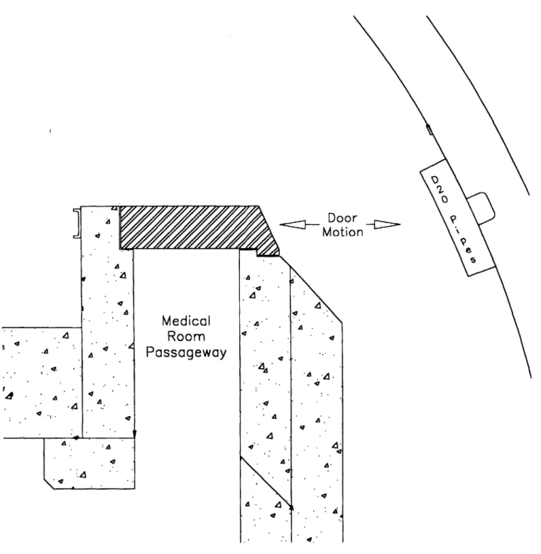
3.6 Chamfered Door -- Conceptual Design
As in the case of choosing the horizontal shutter as the fast shutter
alternative to pursue, engineering judgment, many FCB meetings, and many
special medical room door working group meetings were held to decide which
medical room door alternative to pursue. The advantages and disadvantages
were weighed for each alternative. The result was that the parallel-to-beam
sliding door alternative and the slanted sliding door alternative were combined,
as shown in Figure 3.2. The angled door edge, or chamfer, on the door's side
facing the containment wall is, conceptually speaking, the most desirable
alternative to pursue. This door alternative, nicknamed the chamfered door, is
the overall best alternative such that it mimics the current medical room door
with its sliding movement on the overhead track and trolleys. This approach is
judged to combine the best design alternatives and compromises.
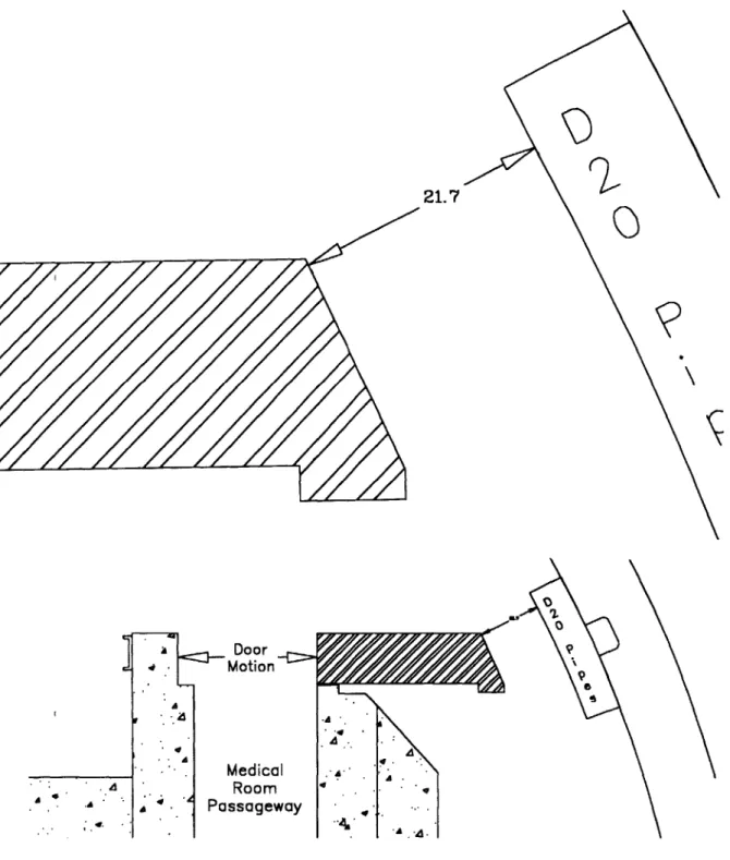
Another advantage to the chamfered door design is that, in its open
position, it leaves enough space between the door edge (chamfer) and the D20
Doorn
Medical
Room
Passageway
Figure 3.2. Chamfered Sliding Door -- Plan View, Closed Position (support
structure for door not shown). A
4.
21.7
2
A
-. Door Motion Medical Room PassagewayFigure 3.3. Chamfered Sliding Door - Plan View, Open Position (support structure for door not shown).
Chapter 4 Water Shutter
4.1 Introduction
The water shutter is an aluminum tank, which can be filled with water. Its
function is to aid the fast shutter in attenuating the neutron and gamma ray dose.
It does this when it is full of water (closed position) as the hydrogen content of
the water attenuates the neutron dose by several orders of magnitude and
attenuates the gamma dose, primarily by photoelectric and Compton scattering
interactions, by about one order of magnitude. When the water shutter is empty
(open position), it allows for unimpeded transmission of the neutron beam to the
patient.
The aluminum tank of the water shutter has a tapered, conical shape so
that it fits inside the funnel-shape of the collimator module. The supply tank for
the water shutter is mounted above the shutter on the medical room roof.
Because the shutter is then filled by gravity, this implies a built-in fail-safe
feature for neutron dose moderation; that is, in the event of a power failure or
other emergency, the manual opening of a valve will fill the shutter. In addition,
the supply pipe and the drainpipe are one and the same. This pipe enters the
the fluidic design and helps to minimize the number of penetrations through the
roof of the medical room.
Water Shutter Fluid Circuit (1
(A Gravity-Fill/Pump-Drain System; Fill/Vent Cover Gas -Flow Switch
-Ta n k)
10/2/98) Burst Disk Level Gouge Omlne Fill UnePump Off Sensor Drain
Clean-up Pump
Vent L.e
4.2 Design Goals and Requirements
In the design of the water shutter fluid circuit, one needs to place the
various tanks, pumps, valves, sensors, gauges, and meters in the correct
locations such that everything works together properly. Proper sizing of the
aforementioned components is also an issue that is very important. The valves
to be used are typically of similar size; however, due to the water shutter fluid
circuit analysis to follow (in Appendix E), it will be shown that some pipes and
vent tubes need to be larger than others. This will enable the water shutter to fill
in a sufficiently quick time, for example. The same water shutter fluid circuit
analysis will produce the size of the main pump needed to drain the water
shutter in a given time.
The clean-up system for the water shutter circuit is a necessary feature
since the circuit is a closed system; the clean-up pump will most likely be a gear
pump which, although having a low volumetric flow rate, can pump against large
heads. It will need to do this since the distance from where the clean-up pump
will be placed -- the equipment room floor -- to the supply tank on the top of the
4.3 Fluidic Design
A concise overview of the water shutter fluid circuit analysis is as follows:
the horsepower needed for the main (drain) pump is found by first computing the
losses due to pumping against gravity, imparting speed to the water, friction and
bends in the pipes, and pumping against the cover gas in the supply tank.
These losses are calculated as functions of shutter drain time; therefore, the
horsepower of the main pump is also a function of shutter drain time.
The next step in the analysis of the water shutter fluid circuit is to compute
the shutter fill time. This is first done by assuming a free discharge of water from
the supply tank (minus the friction and pipe bend losses) to the water shutter.
However, the water entering the shutter will have to force the gas out of the
shutter through the vent line. This gas vent "back pressure" is an added loss
and is calculated as a function of vent tube diameter and added to the friction
and pipe bend losses to yield a "new" shutter fill time.
These calculations are done using both air and helium as the cover gas;
times for air as the cover gas. The water shutter fluid circuit analysis is shown in
its entirety in Appendix E.
Chapter 5 Summary and Suggestions for Future Work
5.1 Summary
Conceptual designs were performed for three components of the
proposed medical facility for the fission converter neutron beam project. These
components were a mechanical shutter, a shielded door for the medical room,
and a water shutter. The two shutters, in their open positions, allow the neutron
beam to reach the patient; in their closed positions, they attenuate the neutron
beam, lowering the radiation levels at the patient position to ~ one mrem/hr. The
shielded door to the medical room allows passage for the patient, medical staff,
and NRL personnel into and out of the medical room. In its closed position, it
attenuates radiation levels outside the door to ~ one mrem/hr even when the
medical beam is on or open.
The mechanical shutter will be constructed of concrete, lead, and
polyethylene -- encased in a steel wrap -- and move horizontally, with respect to
centimeters of polyethylene will be sufficient to attenuate the neutron beam to
one mrem/hr at the patient position (with the other shutters closed).
The shielded medical room door will move parallel to the fission converter
beamline. This door has an edge (on the containment wall side of the door) that
is chamfered, or beveled, to provide the maximum amount of room for personnel
to pass through on that side when the door is in the open position. In addition,
the new medical room door mimics the current medical room door in that it will
move by overhead track and trolleys.
The water shutter will be a tapered, conical, aluminum tank that will fit
inside the collimator module of the fission converter system. The water shutter
will be filled by gravity from a supply tank mounted overhead. Pumping the
water out of the shutter and back up to the supply tank will drain it.
5.2 Suggestions for Future Work
Since this thesis was limited to the conceptual designs of the mechanical
shutter, the medical room door, and the water shutter, there remains the need to
5.2.1 Mechanical Shutter Suggestions
The final dimensions of the fast shutter have yet to be determined; this
will impact the amounts of concrete, lead, polyethylene, and steel that will be
needed. What is known, and has been proven to be sufficient, is that a
thickness of 20 centimeters of polyethylene -- together with a thickness of 20
centimeters of lead -- will be enough to attenuate the neutron beam to ~ one
mrem/hr, with the other shutters closed, an FCB design requirement.
As shown in Figures 5.1 and 5.2, there are four support columns for an
existing overhead platform (not shown) which are located to the left (facing the
reactor) of the horizontal shutter. Figure 5.2 shows the shutter in a full extension
to the left; although the shutter itself does not strike any of the four support
columns, the prime mover, or power source for moving the shutter will be very
difficult to place within these obstructions. The author agrees with M.N.
Ledesma where she suggests in her M.S. thesis Medical Room Design for a
Fission Converter-Based Boron Neutron Capture Therapy Facility (1998) that
some of these support columns may have to be moved. The reason for the
column movement is that two of the support columns (see Figure 5.2) are in
What also needs to be designed is an emergency-closing device for the
fast shutter in the event of a power failure (or other emergency situation) with the
C
'Port p Of
rtfor
5.2.2 Medical Room Door Suggestions
Although the overhead track and trolleys will be used to move the door,
placement of the support columns for the overhead track has yet to be
determined. This placement -- and size -- of the support columns depends on
the total weight of the door, which is also an unknown, but is in the range of ten
to fifteen tons. Door material, or materials, still need to be resolved, although
the author believes that the all-steel door is the optimal medical room door
design. There are three reasons for this choice: the all-steel door is the thinnest
of all door options shown in Tables 3.1 and 3.2 (thereby using a minimum of
floor space), it attenuates gamma rays and fast neutrons better than any other
material considered (except for lead, which as a single door material was ruled
out due to weight) and is of moderate weight, 12.9 tons ( M.N. Ledesma (in her
M.S. thesis Medical Room Design for a Fission Converter-Based Boron Neutron
Capture Therapy Facility, also believed the all-steel door to be the optimal
design for a medical room door)
The weight of the all-steel door is well below the polar crane's weight limit
of 20 tons; additionally, it should be a relatively straightforward matter in locating
5.2.3 Water Shutter Suggestions
The water shutter fluid circuit analysis (in Appendix E) provides insight on
main pump size and tube and pipe diameter sizes, and Figure 4.1 displays the
water shutter fluid circuit; however, what remains to be determined are the exact
placements of both pumps (main and clean-up), the location of the runs of both
piping and tubing, and the material that the supply tank will be made of. Also as
yet undetermined is the placement of the supply tank in amongst the FCB's heat
References
Barth, R.F., Soloway, A.H., and Fairchild, R.G., "Boron Neutron Capture Therapy
for Cancer," Scientific American, October, 1990, vol. 263, issue 4, p.100.
Block, E., Personal Communications, February, 1998 to November, 1998.
Campos, T., Personal Communications, July, 1998 to October, 1998.
Fox, R.W., and McDonald, A.T., Introduction to Fluid Mechanics, John Wiley and
Sons, New York, 1992.
Gere, J., and Timoshenko, S., Mechanics of Materials, Wadsworth, Inc.,
Belmont, California, 1984.
Goldenberg, G., and Chapsky, K., Goldenberg Associates, 24 Fairfax Rd.,
Needham, Massachusetts, August, 1998.
Griffith, P., Personal Communications, February, 1998 to March, 1999.
Kiger, W.S., Neutronic Design of a Fission Converter-Based Epithermal Beam
for Neutron Capture Therapy, Nucl. E. Thesis, Massachusetts Institute of
Technology, 1996.
Kohse, G., Personal Communications, February, 1998 to November, 1998.
Ledesma, M.N., Medical Room Design for a Fission Converter-Based Boron
Neutron Capture Therapy Facility, M.S. Thesis, Massachusetts Institute of
Technology, 1998.
LeGal, A., Ledieu, M., Beam Shutter Design and Medical Room Design, MIT,
September, 1995.
Masse, F., Personal Communication, July, 1998.
McWilliams, F., Personal Communications, February, 1998 to November, 1998.
Menadier, P., Personal Communications, February, 1998 to November, 1998.
Riley, K., Personal Communications, February, 1998 to March, 1999.
Stahle, P., Personal Communications, June, 1998 to November, 1998.
Sutharshan, B., Engineering Design of a Fission Converter-Based Epithermal
Beam for Neutron Capture Therapy, PhD. Thesis, Massachusetts Institute
Appendix A:
A vertically moving shutter (similar vertical geometry to the cadmium
shutter) was the first fast shutter alternative design considered. This shutter
resembles a sluice gate in that it is raised to allow for the passage of neutrons
and lowered to stop the flow of neutrons. In this respect, it has a gravity-driven
fail-safe feature. In other words, upon loss of power (or other emergency), the
shutter fails in the closed position. This feature automatically protects the
patient and medical personnel from excessive radiation levels inside the medical
room.
The initial concept for the vertically moving fast shutter placed it inside the
reactor biological shield, in the thermal column area known as the 'cave.' Inside
the cave, shutter travel length is constrained by the reactor floor and the roof of
the cave. This initial location of the shutter provided inadequate shielding for
the patient with the shutter in the open position.
With the fast shutter in its open position, undesirable radiation exposure
would have been delivered to the patient due to radiation streaming under the
shutter, as shown in Figure A.1 .1.
Likewise, with the fast shutter in the closed position, inadequate shielding
would have resulted with the shutter sitting on the reactor floor, as shown in
Figure A. 1.2. An unimpeded flow of radiation over the top of the shutter would
'~'N.
~tri 1 1 ,
N~NN\
I~I~
%i
Figure A.1.2. Closed Fast Shutter inside Cave.
~%I. -.1 -1 , .1 ., " ,." -. 1 .,. le I" PIQtj trli e
The solution to these shielding problems was to bring the fast shutter
outside of the cave, placing the rear of the shutter flush with the face of the
reactor biological shield. Monte Carlo N-particle (MCNP) calculations (using
MCNP version 4.a) showed that this placement of the shutter and hence, the
patient, further away from the source of the radiation had an acceptable effect on
neutron beam intensity.
Outside the cave, an unlimited amount of material could be added to the
top of the shutter, enhancing the shielding effect in the shutter closed position,
as shown in Figure A.1.3. Nevertheless, the reactor floor still limited the
shielding effect in the shutter open position. Radiation streaming under the
shutter continued to be a problem (see Figure A. 1.4). Also, radiation leakage
through the edge of the shutter aperture and near the top of the aperture
RI.
p l 0
tri
"4
I
1 jI
I 14~~ -- ~-re
~ .. ....
h.
UInc
tict
NN.t
One potential solution to this problem of radiation streaming under the
shutter in the open position was to slide a temporary kneewall, or board, into
place to block the radiation streaming into the medical room. However, this
kneewall would necessarily interfere with the patient positioning system, making
it an unlikely candidate to solve the shielding problem.
One other solution to the shielding problem, that of mining a hole into the
reactor floor, was identified. This hole would enable lengthening the shutter,
through the addition of shielding material placed at the shutter bottom; thereby,
radiation streaming under the shutter in the open position would be minimized
(see Figure A.1.5). The hole idea was considered to be a superior alternative to
the temporary kneewall idea.
In addition to this vertically moving shutter, two circular shutters were
identified as potential fast shutter alternative designs. These circular shutters
are also mounted outside the cave and are flush with the reactor biological
shield, like the vertical shutter. The circular fast shutter idea was first introduced
in A. LeGal's and M. Ledieu's unpublished report Beam Shutter Design and
Medical Room Design, MIT, September, 1995. Appendix A.2 goes into more
FueI Ctrline
Figure A.1.5. Open Fast Shutter Showing Floor Hole.
One circular shutter, named the support wheel circular shutter (SWCS), is
mounted on two support wheels which are themselves mounted by way of
support stands to the reactor floor. One portion of the SWCS is of a
higher-density material than the other. In other words, the SWCS is purposely
unbalanced to maintain the gravity-driven fail-safe feature that the vertical
shutter has.
The other circular shutter, named the center bearing circular shutter
(CBCS), is mounted on a bearing situated at the axis of rotation. As with the
SWCS, the CBCS is purposely unbalanced to provide the gravity-driven fail-safe
feature.
Figures A.2.1 and A.2.2 show these two circular shutters and the
remainder of Appendix A.2 contains the studies done on the two circular
2!!!! tie !3
SW Circular Shutter/ fail-safe position, 6/5/98
(front view, from patient position; 123.7 degrees CW rotattion) Shutter Moss =11.5 tons
ji
B Scal In inch.. a i a a a ''i i 11 F -TC
- - r (1V' ar) - - 0.5 ft. Caling (nominal) LB LCenter Bearing Circular Shutter; 6/3/98
Fail-Safe/Closed Position (122 degrees of CW rotation) (front view, from patient position)
Scale In Inche
S I I s M ,
1111111111111
LB
Lc
Figure A.2.2. Center Bearing Circular Shutter
Support Wheel Circular Shutter Kinematics:
(The following analysis is done only for the SWCS; it is similar for the center bearing circular shutter)
Omax:=n rad : amount of rotation
g :=32.2 ft
2 S
ge :=32.2
T :=10 sec : time to travel
rcm(fleadtopRHS) := rbares(fleadtopRHS) f
12
ft -Ibm
lbf-s2
Ics (fleadtopRHS) :=2000mestotal(fleadtopRHS )- + rcm(fleadtopRHS )2) 8 1.5 -105 1.4 -105 Ics( fleadtopRHS) 0 0 S 1.3 -105 1.2 -105 t :=0,.1..T Omax.( 7C 001t) :=- *sin - t1 2 T o (tl): ax -o (l Omax 21 2 0 0.5 fleadtopRHS fraction of Pb in top RHS t2 :=T,T+ .01.. 2-T Omax:= -o 02(t2) := Cos -2 LT! 2t 2-Rmax 12 ft D=7 ft lbm-ft2 -(t2 - T) + -(t2 - T)] -(t - T)] 7c -Omax w2(C) :=- - 2-T sin[ a2(t2):= - COS