Publisher’s version / Version de l'éditeur:
Vous avez des questions? Nous pouvons vous aider. Pour communiquer directement avec un auteur, consultez la première page de la revue dans laquelle son article a été publié afin de trouver ses coordonnées. Si vous n’arrivez pas à les repérer, communiquez avec nous à [email protected].
Questions? Contact the NRC Publications Archive team at
[email protected]. If you wish to email the authors directly, please see the first page of the publication for their contact information.
https://publications-cnrc.canada.ca/fra/droits
L’accès à ce site Web et l’utilisation de son contenu sont assujettis aux conditions présentées dans le site LISEZ CES CONDITIONS ATTENTIVEMENT AVANT D’UTILISER CE SITE WEB.
4th International Conference on Traffic and Safety in Road Tunnels [Proceedings], pp. 1-13, 2007-04-25
READ THESE TERMS AND CONDITIONS CAREFULLY BEFORE USING THIS WEBSITE.
https://nrc-publications.canada.ca/eng/copyright
NRC Publications Archive Record / Notice des Archives des publications du CNRC :
https://nrc-publications.canada.ca/eng/view/object/?id=8d57a725-72fd-4a87-b6c5-8641043e11d2 https://publications-cnrc.canada.ca/fra/voir/objet/?id=8d57a725-72fd-4a87-b6c5-8641043e11d2
NRC Publications Archive
Archives des publications du CNRC
This publication could be one of several versions: author’s original, accepted manuscript or the publisher’s version. / La version de cette publication peut être l’une des suivantes : la version prépublication de l’auteur, la version acceptée du manuscrit ou la version de l’éditeur.
Access and use of this website and the material on it are subject to the Terms and Conditions set forth at Research progress of the international road tunnel fire detection project
http://irc.nrc-cnrc.gc.ca
R e s e a r c h p r o g r e s s o f t h e i n t e r n a t i o n a l r o a d
t u n n e l f i r e d e t e c t i o n p r o j e c t
N R C C - 4 9 5 0 4
L i u , Z . G . ; K a s h e f , A . ; C r a m p t o n , G . ; L o u g h e e d ,
G . ; A l m a n d , K . H .
A version of this document is published in / Une version de ce document se trouve dans: 4th International Conference on Traffic and Safety in Road Tunnels, Hamburg, Germany, April 25-27, 2007, pp. 1-13
The material in this document is covered by the provisions of the Copyright Act, by Canadian laws, policies, regulations and international agreements. Such provisions serve to identify the information source and, in specific instances, to prohibit reproduction of materials without written permission. For more information visit http://laws.justice.gc.ca/en/showtdm/cs/C-42
Les renseignements dans ce document sont protégés par la Loi sur le droit d'auteur, par les lois, les politiques et les règlements du Canada et des accords internationaux. Ces dispositions permettent d'identifier la source de l'information et, dans certains cas, d'interdire la copie de documents sans permission écrite. Pour obtenir de plus amples renseignements : http://lois.justice.gc.ca/fr/showtdm/cs/C-42
Research Progress of the International Road Tunnel Fire Detection Project
Z. G. Liu1, A. Kashef, G. Cra mp to n and G. Lougheed, Fire Research Program, Institute for Research in Construction
National Research Council of Canada, Ottawa, Canada Kathleen H. Almand
The Fire Protection Research Foundation, Quincy, MA, USA
1. INTRODUCTION
Fire detection systems are an essential element of fire protection systems of road tunnels. Fire detectors should provide early warning of a fire incident at its initial stage, identify its location and monitor fire development in tunnels. Their role is crucial in preventing smoke spread in the tunnel, to controlling/extinguishing fires, and to aid in directing evacuation and firefighting operations [1-3].
Recent studies, however, indicated that information on the performance of current fire detection technologies and guidelines for t heir use in ro ad t u n nel p rotectio n are limited [4]. Relatively few test programs that mainly focused on the performance of linear heat detection systems and optical flame detectors were conducted in Europe and Japan [5-11]. Many other types of fire detection technologies, such as spot heat detectors, smoke detection systems and newly developed visual flame and smoke detectors have not been studied systematically. In addition, there are no generally acceptable test protocols and performance criteria for use in the evaluation of various fire detection technologies for tunnel protection. The test conditions and fire scenarios were changed from one test program to another one. The performances of detectors in these programs were evaluated mostly with pool fires of a constant heat release rate of up to 3 MW. Other types of fire scenarios, such as stationary and moving vehicle fires, were not considered. Another concern on the use of current fire detection systems is that their reliabilities, including their false alarm rates and maintenance requirements in smoky, dirty and humid tunnel environments, have not been systematically investigated.
The National Research Council of Canada (NRCC) and the Fire Protection Research Foundation (FPRF), with support of government organizations, industries and private sector organizations, initiated Phase II of an international project that aims to investigate the application of current fire detection technologies for roadway tunnel protection [12, 13]. The project includes studies on the detection performance of current fire detection technologies with both laboratory and field fire tests combined with computer modeling studies. In addition, the project includes studies on detector reliability in a roadway tunnel environment. Some project tasks have been completed and others are ongoing. This paper provides an overview of the progress of the project. The fire detectors, fire scenarios and test protocols that are used in the test program are described. Some research results from a series of full-scale fire tests conducted in a test tunnel and from computer modeling are reported.
2. SELECTED FIRE DETECTORS/DETECTION SYSTEMS
Nine fire detectors/detection systems have been identified for study in the project by
1
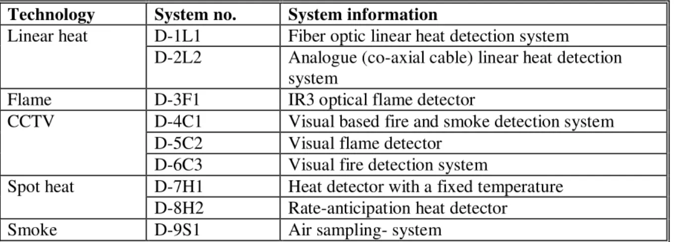
the Technical Panel [14]. These detectors/systems cover five types of currently available technologies. They are: two linear heat detection systems, one optical flame detector, three visual CCTV fire detectors, one smoke detection system and two spot heat detectors. These detectors/systems provide a good representation of current fire detection technologies for use in tunnel fire detection. Information on these detectors/systems is listed in Table 1.
Table 1. Fire Detectors/Detection Systems in the Project
Technology System no. System information
D-1L1 Fiber optic linear heat detection system Linear heat
D-2L2 Analogue (co-axial cable) linear heat detection system
Flame D-3F1 IR3 optical flame detector
D-4C1 Visual based fire and smoke detection system D-5C2 Visual flame detector
CCTV
D-6C3 Visual fire detection system
D-7H1 Heat detector with a fixed temperature Spot heat
D-8H2 Rate-anticipation heat detector Smoke D-9S1 Air sampling- system
System D-1L1 is a fiber optic linear heat detection system based on Raman scattering. The optical fiber is used as the sensing medium. During operation, light signals are sent into the optical fiber from a laser light source (Figure 1). As pulses travel down the fiber, light is lost through scattering. A portion of the scattered signal is directed back along the fiber towards the laser source. Part of the back-scatter signal (Raman Scattering) is used to provide remote temperature measurements as changes in temperature alters the refractive indices and geometric properties of the optical fiber, which perturbs the intensity, phase, and polarization of the light wave propagating within the fiber. Fire warning signals are given based on rate of temperature rise and/or exceeding a fixed temperature. The system can also provide information on the fire location along the length of the fiber cable.
Figure 1. Operating principle of System D-1L1
System D-2L2 is an analogue (coaxial cable) linear heat detection system. The sensor cable consists of a conductor, an insulating layer with a resistivity that decreases with increasing temperature, and a metal-weaving screen layer (Figure 2). During a fire incident,
the resistance between the conductor and the metal screen drops due to the increase in temperature. The changes in the resistance can then be monitored using a control module, and a fire warning signal provided based on rate of temperature rise or exceeding a fixed temperature.
Figure 2. Schematic of the sensor cable of System D-2L2
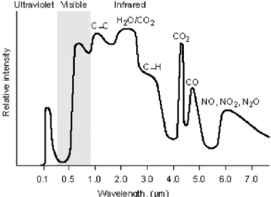
System D-3F1 is a multi-spectrum infrared (IR) optical flame detector. It contains three IR sensors: one covers the typical CO2 flame emission spectral band (Figure 3) that is
responsible for the detection of flame radiation, and the other two sensors cover different, adjacent, and specially selected spectral bands, where black body emitters and background radiation are produced and are used to minimize false alarms.
Figure 3. Spectral emissions from a gasoline fire
Systems D-4C1 and D-5C2 are Closed Circuit Television (CCTV) flame and smoke detection systems. They use a combination of video cameras, computers, and artificial intelligence techniques (Figure 4) for fire detection. A video charged-couple device (CCD) camera is used to monitor the environment and possible fire incident. The spectral output of the camera is stored in computer memory as a function of time and space. Pattern recognition and image processing techniques are used to analyze the images on the fly. Fire alarms will be issued, once the characteristics of flame and smoke are identified. Video images provided by the system are also used to track and monitor fire growth.
Figure 4. Operating principles of a CCTV fire detection system
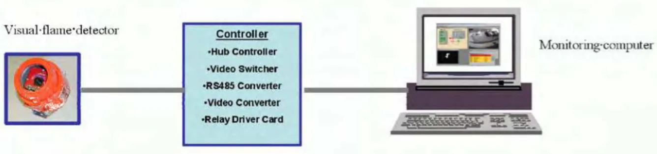
System 6C3 is another type of CCTV flame detection system. Unlike Systems D-4C1 and D-5C2, image sensing and processing are combined into one detector, and fire information and videos are directly sent to the monitoring computer through a controller, once a fire incident is identified (Figure 5).
Figure 5. Operating principle of System D-6C3
System D-7H1 is a pneumatic, spot type heat detection system based on frangible bulb technology (Figure 6). The device is fitted on a sensing line pressurized using nitrogen. During a fire incident, the air trapped in the line will be released as the detector is activated, triggering a pressure switch that provides a fire signal and indicates the fire position as the location of the detection segment.
Figure 6. Spot type heat detector of System D-7H1
System D-8H2 is a rate-anticipation spot heat detector (Figure 7). It responds and activates the fire alarm when the ambient temperature reaches the preset temperature setting.
Under rapid heat rise conditions, its rate-anticipation feature also enables the detector to respond one to three degrees ahead of the temperature setting.
Figure 7. Spot type heat detector of System D-8H2
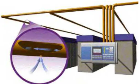
System D-9S1 is an air sampling-type smoke detection system. Air is continuously drawn into a pipe network through holes in the piping to a centrally-located smoke detector using an air pump or aspirator (Figure 8). The density of smoke in the sampled air is then compared to a set of pre-defined smoke thresholds. Alarms will be issued, if the amount of smoke in the sampled air exceeds the thresholds.
Figure 8. Operating principle of System D-9S1
3. FIRE TEST PROTOCOLS AND SCENARIOS
Three types of fire scenarios, involving various fire sizes, types, locations and growth rates, were selected for use in evaluating the performance of the tunnel fire detection systems. These fire scenarios are considered representative of the majority of tunnel fire incidents [3, 4, 15-17]:
• Liquid pool fires caused by fuel leaking from a vehicle or in a collision. The fire
develops very quickly and reaches its maximum heat release rate in a short time;
• Stationary passenger vehicle fires caused by collision incidents, by an electrical
failure or by a defective fuel delivery system and exhaust system failures. The fire develops slowly and it takes 8~12 minutes for a vehicle fire to reach its maximum heat release rate; and
• Moving vehicle fires caused by an electrical failure or by a defective fuel delivery
system and exhaust system failures. The fire moves through the tunnel at various speeds.
3.1. Pool Fires
Two pool fire scenarios were used in the test program:
• Pool fire scenario I – a pool fire underneath the vehicle, representing a challenging tunnel pool fire as the fuel leaks and forms a pool underneath the vehicle.
• Pool fire scenario II – an open pool fire behind a large vehicle, representing a more general tunnel pool fire as fuel leaks and forms a pool behind the vehicle.
For pool fire scenario I, a steel plate was located 0.3 m (1 ft) above the pan used for the pool fire. The plate had an area of 1.5 m (5 ft) wide by 2.4m (8 ft) long, which is similar to the bottom area of a standard passenger vehicle. A vehicle mock-up with a size of 1.5 m (5 ft) wide by 1.2 m (4 ft) high, simulating a crashed car located between the fire source and the wall-mounted detectors, was placed 1.5 m in front of the fire source and 0.3 m (1 ft) above the ground.
The size of the pan placed underneath the plate ranged from 0.3 m x 0.3 m to 1.0 m x 2.0 m. A propane burner that had a controlled heat release rate was also used to simulate pool fires underneath a vehicle. No smoke was generated from the propane fires. The fire sizes in the test program were varied from approximately 100 KW to 3,400 kW.
For pool fire scenario II, an open pan fire was placed behind a large metal plate. The metal plate had a size of 2.5 m (8.3 ft) wide by 4.2 m (14 ft) high and was representative of the size of a large truck. It was placed 6 m (20 ft) in front of the pool fire and 0.3 m (1 ft) above the ground, which simulates the front portion of a crashed truck located between the pool fire and the detectors. The distance between the edge of the metal plate and the wall of the tunnel was 0.5 m (1.7 ft). The size of the pan placed behind the obstacle ranges from the size of 0.3 m x 0.3 m to the size of 1.0 m x 2.0 m. The fire sizes in the test program were varied from approximately 100 KW to 3,400 kW.
3.2. Stationary Vehicle Fires
A stationary vehicle fire can start from the engine compartment, from the passenger area, or from the fuel tank and trunk area [18, 19]. The fire growth rate is slower than a hydrocarbon pool fire and it can take a long time for the flame to spread to the rest of the vehicle [20, 21]. Two stationary vehicle fire scenarios were used in the test program: an engine compartment fire and a passenger compartment fire. No obstacles were located between the fire source and the detectors.
For an engine compartment fire scenario, a simulated vehicle engine compartment with a dimension of 1.5 m (5 ft) wide x 1.2 m (4 ft) long x 0.67 m (2.2 ft) high was used. A gasoline fuel pan with controlled heat release rate was placed inside the compartment and used to generate an engine compartment fire. The heat release rate was similar to one
generated in a real vehicle engine compartment fire [20, 21]. It took approximately 8 minutes for the vehicle engine compartment fire to reach its maximum heat release rate (2,000 kW).
For a passenger compartment fire scenario, a mock-up simulating the front portion of a vehicle passenger compartment with dimensions of 1.5 m (5 ft) wide x 1.2 m (4 ft) long x 1.2 m (4 ft) high was used. It was assumed that during the fire incident, the door at the driver side of the vehicle was left open, as the driver escapes from the burning vehicle. Wood cribs were placed inside the compartment and used as the fire source. An alcohol pan fire placed underneath the wood crib was used as the ignition source. The heat release rate of the fire was similar to one generated in a real vehicle passenger compartment fire [20, 21]. It took approximately 10 minutes for the fire to reach its maximum heat release rate (1.1 ~ 1.5MW).
3.3. Moving Vehicle Fires
A moving vehicle fire can be caused by many factors including a fuel delivery failure that is ignited by hot exhaust components [18, 19]. The most common scenario is a parking brake that is left engaged causing the brake drum to overheat resulting in the rupture of the hydraulic slave cylinder seals. When this happens, the brake fluid is released into the drum and subsequently ignites. The wheel involved is in the rear of the vehicle and can go unnoticed by the driver. The fire eventually destroys the tire and spreads to the rear bumper and fuel tank once the vehicle stops. The moving vehicle fire is not only a realistic scenario that has occurred on many occasions in tunnels, but it is also a challenge for a detection system [4]. Since it can quickly develop into a large fire, early detection is important. The detecting capability of the various detection systems to a moving fire was evaluated in the test program.
The heat release rate of the moving fire was approximately 100 ~ 150 kW, when the fire source was at rest. There was no obstacle around the fire source. Fire tests with different driving speeds and driving directions relative to the detectors were conducted.
4. FIRE TESTS IN A LABOROTORY RESEARCH TUNNEL
A series of full-scale fire tests were conducted in a research tunnel facility. The dimension of the tunnel facility is 10 m wide x 5.5 m high x 37 m long (30 ft x 16.5 ft x 113 ft long). Natural ventilation was maintained in the tunnel during tests.
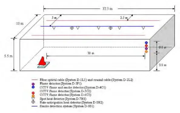
Nine fire detection systems selected by the Technical Panel were installed in the tunnel by the system suppliers. It was required that the configuration and installation of the fire detection systems in the test tunnel be designed assuming a road tunnel with a dimension of 10 m wide x 5.5 m high x 2,000 m long (30 ft x 16.5 ft x 6,100 ft long) was being protected. As shown in Figure 9, two parallel sensing cables of each linear detection system were installed on the ceiling of the tunnel. Each cable was located at approximately 80 mm from the ceiling, 2.5 m from the wall and 5 m from the other detection cable. A pneumatic, spot type heat detection system with a steel pipe and an air sampling-type smoke detection system were installed along the center of the test tunnel. Two rate-anticipation spot heat detectors were also installed along the center of the tunnel ceiling at 15 m spacing and at 110 mm from the ceiling. All the flame and CCTV detectors were installed at the same location on the north side of the test tunnel but with different elevations. The outputs of these
Figure 9. Schematic of detector setup in the test tunnel
detection systems were sent to a data acquisition system.
The locations of the detectors were not changes during the test program. It was also required that the sensitivity level or alarm threshold of the fire detection systems in the test program should be set up the same as one used in an operating tunnel and be consistent with those used in the operating environment tests in the Lincoln tunnel. They were also not allowed to be changed during the test program.
The detecting capability and limitation of all nine detectors/detection systems were evaluated under the same fire test conditions. Twenty-one full-scale fire tests were conducted. The fire scenarios used in the tests included pool fires, stationary vehicle fires and moving fires of various sizes (100 kW to 3,500 kW); various growth rates (1 min to 12 min for reaching their maximum heat release rates); various locations (open space fire, fires underneath a vehicle and behind a large vehicle) and various fuel types (gasoline, propane, wood crib and foam); and fires with various moving directions and speeds.
The performance of the selected fire detection systems in the tests was dependent on the fire scenarios encountered. It was difficult for linear heat detection systems and optical flame detector to detect a small fire underneath the vehicle, because both heat and flames generated from the fire were confined beneath the vehicle. However, they were able to detect all other fires used in the tests. The visual CCTV flame and smoke detector detected all the fires used in the tests, since it was able to respond to both flame and smoke signals generated by fires. The visual CCTV flame detector, however, only responded to the fires with visible flames that it could view. It was difficult for the detector to detect the small fires underneath the vehicle and fires behind large vehicle, as its view to the flames was blocked. Two spot heat detectors responded to large fires (>1,500 kW) used in the tests but they could not detect small fires. The smoke detection system evaluated had no response to the propane fires, since no smoke was generated, but it detected all other fires used in the tests. Only the
optical flame detector was able to detect a moving fire at the speed of 27 km/h and all other detectors/detection systems had no response to this scenario. The detailed test results conducted in the laboratory tunnel will be reported separately.
5. COMPUTER MODELING
Due to the rapid development of computer technology and huge costs of test programmes, the use of Computational Fluid Dynamics (CFD) models to simulate the dynamics of fire behaviour in tunnels is increasing quickly. The details of fluid flow and heat transfer provided by CFD models can prove vital in analyzing problems involving far-field smoke flow, complex geometries, and impact of fixed ventilation flows.
The current research study employs the Fire Dynamic Simulator (FDS) CFD model [22, 23] to study the fire growth and smoke movement in road tunnels. FDS is based on the Large Eddy Simulation (LES) approach and solves a form of high-speed filtered Navier-Stokes equations valid for a low-speed buoyancy driven flow. These equations are discretized in space using second order central differences and in time using an explicit, second order, predictor-corrector scheme.
The research study uses the CFD technique to:
• Conduct preliminary CFD simulations to assist in the preparation of full-scale experiments
• Compare numerical predictions against full-scale experimental data
• Investigate the impact of various fire scenarios, ventilation mode, tunnel operating conditions and tunnel geometries on fire behaviour and detection systems performance. Information from the model will be used in developing appropriate test protocols and for understanding and optimizing the performance of fire detection systems used for road tunnel protection.
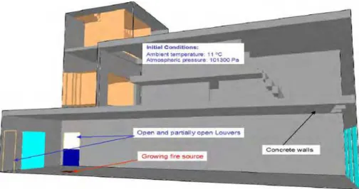
CFD simulations were carried out to compare numerical predictions against the data from a demonstration fire test in the laboratory tunnel. A 1 m x 1.75 m gasoline pool fire source was used in this test. A total heat release rate of about 3.0 MW was produced. Figure 10 shows the modelled domain, initial, and boundary conditions used in the numerical simulations of the test. The results from the numerical simulations indicated that the airflow velocity within the tunnel was about 0.25 m/s and that the hot layer depth was about 1.5 m from the ceiling. These predictions compare well with the measurements (during in-situ tests, depth was measured to be about 1.2 m in the vicinity of fire and the airflow velocity was in the range of 0.15-0.20 m/s).
Figure 10. Demonstration test: computational domain, initial and boundary conditions
Figure 11 shows sample comparisons of predicted and measured temperatures at the thermocouple drop close to the fire source (Figure 11a) and at the ceiling (Figure 11b). The discrepancies between the two set of data in Figure 11a can be attributed to the effect of radiation on the thermocouple readings which was not accounted for in the numerical model. Figure 11a indicates a hot layer depth of about 1.5 m from the ceiling. The effect of radiation is reduced for thermocouples located further from the fire source and thus Figure 11b reflects good comparisons of predicted and measured temperatures.
(a) Thermocouple drop at fire (b) Ceiling thermocouple
Figure 11. Numerical predictions versus experimental data
6. OTHER RESEARCH ACTIVIES
The effect of longitudinal ventilation on the performance of fire detection systems in tunnel environment will also be investigated. A series of full-scale fire tests will be conducted in the laboratory tunnel. The setup of the fire detection systems and fire conditions used in the tests will be similar to those used for tests under natural ventilation conditions. Various longitudinal air velocities up to 3 m/s will be used in the tests. The results will be compared with those under natural ventilation conditions.
A series of field fire tests will be conducted in an operating road tunnel in Montreal, Canada, in collaboration with the Ministry of Transport of Quebec (MTQ). The tunnel has a dimension of 2,500 m long, 5 m high, 16.8 m wide (representing 4 lanes). The performance
of fire detection systems in a real tunnel environment and at their maximum detecting distance will be investigated in these tests. The results will be compared with those conducted in the laboratory tunnel. The fire scenarios will include open pool fires, pool fires underneath the vehicle and behind the vehicle under natural and longitudinal ventilation conditions.
Selected fire detection systems have been installed in the Lincoln tunnel in cooperation with the Port Authority of New York and New Jersey (PANYNJ). The tunnel has a dimension of 2,441 m long, 4.15 m high and 6.6 m wide. These detectors are being monitored over a one-year period to determine the influence of environmental conditions on the performance of the fire detection systems. The hits/misses/false alarms generated by the detection systems and maintenance requirements for the systems will be recorded. Other environmental data such as temperature, humidity and weather may be collected and recorded on a regular basis if necessary.
A series of full-scale fire tests will be conducted in the Lincoln Tunnel. The response capability of selected fire detectors/detection systems to various tunnel fire scenarios will be investigated. Video recording of the test series is under consideration. The additional testing will provide valuable information to the project, since the geometry and ventilation conditions of the Lincoln tunnel are different from those in both the lab tunnel and the Montreal tunnel.
7. SUMMARY
Nine fire detection systems have been identified and used in the present project. These systems provide a good representation of current fire detection technologies for use in tunnel fire detection. A test protocol for evaluating various fire detection technologies for road tunnel protection has also been developed. The performance of selected fire detection systems for various tunnel fire scenarios was investigated in a laboratory tunnel under natural ventilation conditions. Computer modeling was used to investigate the impact of various fire scenarios, ventilation mode, tunnel operating conditions and tunnel geometries on fire behaviour and detection systems performance. Selected detection systems have also been installed in the Lincoln tunnel and their reliability in real tunnel environments are being monitored over a one-year period. The impact of longitudinal ventilation and real tunnel environments on the fire detecting capability of these systems will also be studied in the laboratory and operating tunnels.
ACKNOWLEDGEMENT
Contributions of following organizations to the project are acknowledged:
Ministry of Transportation of British Columbia Ministry of Transportation of Ontario
Ministry of Transportation of Quebec
The City of Edmonton, Transportation Department, Transit Projects Branch Port Authority of New York and New Jersey
Carleton University
axonX LLC/Johnson Control Siemens Building Technologies
Tyco Fire Products VisionUSA
Sureland Industrial Fire Safety
United Technologies Research Corporation J-Power Systems/Sumitomo Electric USA, Inc. A & G Consultants
PB Foundation Micropack, Inc. Honeywell Inc.
The authors would also like to acknowledge the contributions of the Technical Panel members and other NRC staff to this project, as well as Professor G. Hadjisophocleous and Ms. Y. Ko of Carleton University for their contributions to computer modeling study in the project.
References
1. PIARC, “Fire and smoke control in road tunnels,” World Road Association, 1999. 2. NFPA 502, “Standard for Road Tunnels, Bridges, and other Limited Access
Highways,” National Fire Protection Association, 2004
3. U.S. Department of Transportation, Federal Highway Administration, “Prevention and Control of Highway Tunnel Fires,” FHWA-RD-83-032, 1984.
4. Zalosh, R and Chantranuwat, P., “International Road Tunnel Fire Detection Research Project, Phase 1: Review of Prior Test Programs and Tunnel Fires,” The Fire Protection Research Foundation, November 2003.
5. H. Ishii, K. Kawamura, T. Ono, H. Megumi, and A. Kikkawa, “A fire detection system using optical fibres for utility tunnels,” Fire Safety J. 29 (1997) 87-98.
6. H. Mashimo, “State of the Road Tunnel Safety Technology in Japan,” Tunnelling and Underground Space Technology, 17 (2002) 145-152.
7. Capaul, T., “Evaluation linear temperature sensor response testing in Mositunnel, Switzerland, June 11-12, 1992,” Cerberus Report, 1992.
8. Magerle, R., “Fire Protection Systems for Traffic Tunnels Under Test,” Proceedings AUBE 01 Conference, NIST, 2001.
9. Juzo Unpki and Shoichi Kimura, “New Fire Detecor for Road Tunnels,” Fire Safety Journal, P.215-224, 6, 1983.
10. Azuma, T., Gunki, S., Ichikawa, A. and Yokota, M., “Effectiveness of a Flame Sensing Type Fire Detector in a Large Tunnel,” 6th International Conference on Safety in Road and Rail Tunnels, Marseilles, France, October 2004
11. Brugger, S. “Rapid Fire Detection Concept for Road Tunnels,” 5th International Conference on Safety in Road and Rail Tunnels, Marseilles, France, October 2004 12. Liu, Z.G., Kashef, A., Lougheed, G.D., Su, J.Z., Bénichou, N., Almand, K. H., "An
Overview of the international road tunnel fire detection research project," 10th Fire Suppression and Detection Research Application Symposium, Orlando, FL., U.S.A. February 01, 2006
13. Almand, K.H., Liu, Z.G., Kashef, A. "North American road tunnel fire detection research project," 2nd International Symposium on Tunnel Safety & Security, Madrid, Spain, March 15, 2006
14. Z. G. Liu, G. P. Crampton, A. H. Kashef, G. D. Lougheed, E. Gibbs, J. Z. Su and N. Benichou, “ International Road Tunnel Fire Detection Research Project – Phase II:
Task 1, Fire Detectors, Fire Scenarios and Test Protocols,” NRCC Client Report (B-4179.1), July 2006
15. FIT European Thematic Network, “Fire Safety Design – Road Tunnel” Draft 2, September 2003
16. Ingason, H. Lonnermark, A., “Recent Achievements Regarding Measuring of Time-Heat and Time Temperature Development in Tunnels,” 1st International Symposium on Safe & Reliable Tunnels, Prague, April 2004.
17. R.O. Carvel, A.N. Beard, P.W. Jowitt, and D.D. Drysdale, “The Influence of Tunnel Geometry and Ventilation on the Heat Release Rate of a Fire,” Fire Technology, 40, 5-26, 2004
18. International Association of Arson Investigators, Alberta Chapter, “A study of vehicle fires of known ignition source,” Jan. 1983
19. R. Hrynchuk, “CAFI vehicle fire investigation techniques, A report on Vehicle Fire Tests,” Canadian Association of Fire Investigators Seminar, Sept. 30, 1998, Toronto, Ont.
20. J. Mangs and O. Keski-Rahkonen, “Characterization of the Fire Behaviour of a Burning Passenger Car, Part I: Car Fire Experiments,” Fire Safety Journal 23 (1994) 17-35
21. J. Mangs and O. Keski-Rahkonen, “Characterization of the Fire Behaviour of a Burning Passenger Car, Part II: Parametrization of Measured Rate of Heat Release Curves,” Fire Safety Journal 23 (1994) 37-49
22. A, Kashef, N. Benichou, G. Lougheed and A. Debs "CFD simulations of in-situ fire tests in road tunnels," Tunnel Management International Journal, 7, (4), December, pp. 1-10, December 01, 2004
23. McGrattan, K.B., Fire Dynamics Simulator (Version 4) – Technical Reference Guide, NIST Special Publication 1018, National Institute of Standards and Technology, Gaithersburg, MD, 2005.