Publisher’s version / Version de l'éditeur:
Vous avez des questions? Nous pouvons vous aider. Pour communiquer directement avec un auteur, consultez la
première page de la revue dans laquelle son article a été publié afin de trouver ses coordonnées. Si vous n’arrivez pas à les repérer, communiquez avec nous à [email protected].
Questions? Contact the NRC Publications Archive team at
[email protected]. If you wish to email the authors directly, please see the first page of the publication for their contact information.
https://publications-cnrc.canada.ca/fra/droits
L’accès à ce site Web et l’utilisation de son contenu sont assujettis aux conditions présentées dans le site
LISEZ CES CONDITIONS ATTENTIVEMENT AVANT D’UTILISER CE SITE WEB.
Internal Report (National Research Council of Canada. Division of Building Research), 1958-04-01
READ THESE TERMS AND CONDITIONS CAREFULLY BEFORE USING THIS WEBSITE. https://nrc-publications.canada.ca/eng/copyright
NRC Publications Archive Record / Notice des Archives des publications du CNRC :
https://nrc-publications.canada.ca/eng/view/object/?id=1164ca6d-3611-4210-916b-de1e6c2e38e0 https://publications-cnrc.canada.ca/fra/voir/objet/?id=1164ca6d-3611-4210-916b-de1e6c2e38e0
Archives des publications du CNRC
For the publisher’s version, please access the DOI link below./ Pour consulter la version de l’éditeur, utilisez le lien DOI ci-dessous.
https://doi.org/10.4224/20386704
Access and use of this website and the material on it are subject to the Terms and Conditions set forth at Arctic hut heating and ventilation trials
NATIONAL RESEARCH COUNCIL OF CANADA DIVISION OF BUILDING RESEARCH
ARCTIC HUT
HEATING AND VENTILATION TRIALS
by
A.D. Kent
ANAL YZED
(A eo-operative project with the Direotorate of Engineer Development, Department of National Defenoe (Army»)
Report
No.
137
of the
Division of Building Researoh
Ottawa
It is a special pleasure for the Division of Building Research to issue this report on one of the most extensive co-operative projeots whioh it was privileged to carry out in its early years of operation. It was the very extent or the work herein desoribed whioh made the study and assessment of the mass of experimental records so time-consuming a task. Apologies are here recorded for the lateness of this report, but the delay in its final oompletion has been inevitable due to the essential claims of more pressing work upon the member of staff ooncerned, Mr. A.D. Kent, who is an Assistant Research Offioer in the Building Services Section of the Division.
The Division welcomed the opportunity of working with the Directorate of Engineer Development of the Canadian Army in a number of studies relating to the performance of the prefabricated huts developed by DED for Army use. Study of the actual performance of one of these huts, when used in a particularly isolated and cold location, gave the Division an unusual opportunity for obtaining much information of value regarding not only the performance of the Army huts, but the winter performance of buildings in general.
Preliminary reports on the winter's operations, herein described in detail, were made to Army authorities shortly after the completion of the work. In view of this it has been possible to study all the records obtained with unusual care. The results of these studies are now presented in this report. Comments and criticisms will be welcomed by the Division,
partioularly since it is hoped that, if thought to be of sufficient interest, the more important results presented in this report may, in due course, be published.
The Division records its thanks to the Directorate of Engineer Development for the opportunity of co-operating in
the work described, and to the many members of the staff of DED who helped with the work involved.
ottawa
TABLE OF CONTENTS
.
1. INTRODUCTION-
•
• ••
• • • • • • • • • • • • • • • • ••
1 ARCTIC HUT HセセセSQ• • • • • • • • • • • • • • • . • • • •
(a) GAneral • • • • • • • • • • • • • • • • • • • • • •Tl)
VVafl Panels • • • • • • • • • • • • • • • • • • (2) Window Panels • • • • • • • • • • • • • • • • • (3) Floor Panels • • • • • • • • • • • • • • • • • (4) Roof Panels • • • • • • • • • • • • • • • • • • (5) Special Features • • • • • • • • • • • • • • • Don,1ek Prototm •• • • • • • • • • • • • • • • • (1) Erection-3J.te • • • • • • • • • • • • • • • • • (2) Interior Arrangement • • • • • • • • • • • • • (3) Caulking • • • • • • • • • • • • • • • • • • • (4) Services • • • • • • • • • • • • • • • • • •• HセI Heating Equipment • • • • • • • • • • • • • • • (0) Ventilation Equipment • • • • • • • • • • • • • (b) METHODS OF TEST • • ••
••
• • ••
• • ••
• • ••
• ••
2 2 2 3 3 3 3It
li
t
4
5
6 (b) Envirornnent • • • • • • • • • • • • • • • • • • • •(1)
Room Air (dry bulb) Temperature • • • • • • • •(2) Panel Surface Temperatures • • • • • • • • • •
(3) Room Air Relative Humidity • • • • • • • • • •
(It) Ventilation Rate • • • • • • • • • • • • • • •
(5) Air Quality • • • • • • • • • • • • • • • • • •
INSTRIDJlENTATION AND MEASUREMENTS
4.
(a)
. . . .0.
M8teorological Data • • • • • • • • • • • • • • • •
(1) Outside Air
(dry
bulb) Temperature • • • • • •(2) Outside Air Relative Humidity • • • • • • • • •
(3) Wind Velocity and Direction • • • • • • • • • •
Uf.} Depth of Snow Cover on Roof • • .- • • • • • • •
(5) General Weather Observations • • • • • • • • •
7 7 7
9
9 10 10 10 11セセ
16
20(2 ) Total Heat Loss •
•
• • • ••
•
••
•
•
•
••
"
(i) Heat Loss through Roof Vent • •
• •
•• •
(Ii) Heat Loss through Draft Regulator •
•
• •
(iIi) Heat Loss to Flue Gas
•
• • • ••
• •• •
(iv) Heat Loss' to Combustion Air
•
• • •
•
•
•
(v) Heat Loss through the Structure • • •
• •
(vi) Summary of Heat Losses
•
••
•
••
••
•
•
•
••
••
•
••
••
••
•
•
• • • • • • • • • • • • • 0 •
of Fue1 • • • • • • • • • • •
Heat Input • • • • • • • • • • from Personnel • • • • • • • •
(d) Ground Surface TemEeratures ••
21 21 22
23
23
24
25
20
2728
28
323
23
2 • • • • • • 0 • • • • •• ••
•
•
• ••
•
• • • • • • • (3) Heat Balance Heat Balance • • • •(1)
Total Heat Input(i) Heat Input
(ii) Electrical
(iii) Heat Input
rセferences • • • • • • • • • • • • • • • • • • • • • • •
(e) VAntilation System Performanoe • • • • • • • • • •
(2) Panel Surfaoe Temperatures • • • • • • • • • • (3) Room Air Relative Humidity • • • • • • • • • •
(4) Ventilatlon Rate • • • • • • • • • • • • • • •
(d) Heating System Perrormance • • • • • • • • • • • •
rrnea
ter Capaoity • • • • • . • . • • • . • • • •
(2) Temperature Distribution • • • • • • • • • • • (3) Ease of Operation and Maintenanoe • • • • • • •
34
34
4
セT
35
36
38 3840
40
41
42
43
tt
ttl
3
44
45
45
エエセ
46
117
47
48
48
50
50
•
•
•
• •
•
• •
•
•
•
••
••
• •
•
• • ••
•• •
• ••
• •
•• • •
••
••
•
•
•
•
••
•
• •
• •• •
• •
• •• •
• •
• •
• ••
• • • • • • • • • • • • • • • •• •
••
• • • •• •
•
•
• •
(0) Heat Losses to the Ground • •
(a) Air Temperatures •
• •
• •• •
•
••
•
•• •
•
•
•
(b) Surfaoe Temperatures
•
• • • •
•
••
•• •
••
• •
(0 ) Relative Humidity
•
• • • •• •
• • •• • •
••
•
•
(d) Air Motion
•
••
•• •
••
•• •
• ••
•
•• • •
•
(e) Air Quality
• • •
• ••
• • •• • •
• • ••
•
•
•
•
(f) C-eneral•
•
••
·
'.
• •
••
• • • •• • •
••
• •
•
(a) Environment • • • • • • • • • • • • • • • • • • • • (1) Room Air Temperature • • • • • • • • • • • • • (1) Horizontal Temperature Distribution • • • (11) Vertioal Temperature Distribution • • • •(b) Heat Balance • • • • • • • • • • • • • • • • • • • (1) Heat Input • • • • • • • • • • • • • • • • • • (2) Heat Losses • • • • • • • • • • • • • • • • • • (3) Heat Balance • • • • • • • • • • • • • • • • • ANALYSIS OF DATA COMFORT REACTIONS CONCLUSIONS • ACKNOWLEDGMENTS
7.
8.6.
APPENDIX A Table of Results
APPENDIX B Theoretical Overall Heat Transmission Coeffioients for Arctio Hut Panels
APPENDIX C Computation of Maan Room Air Temperatures APPENDIX D - Fuel Analyses
ARCTIC HUT
HEATING AND VENTILATION TRIALS
by A.D. Kent
In
1950
the Direotorate of Engineer Development, Departmentof National Defenoe
(Army)
completed the development of the Mark 3version of the Prefabricated Arctic Hut based on field experience
and previous trials of the Mark 1 and 2 versions. Following its
development, a prototype of the Arctio hut
(Mk.3)
underwent a seriesof trials to determine its general suitability for Arctic troop
aooommodation. These trials included transportation, assembly and
disassembly, occupanoy, struoture, materials, and heating and ventilation.
The Division was privileged to assist the Directorate in the planning, instrumentation, supervision, and subsequent data analysis of the heating and ventilation trials which were conducted
from Ootober
1950,
to April1951
at Donjek River Camp, Yukon Territory.The purpose of the heating and ventilation trials was to
test the oooupied hut under field operating conditions, and specifically to determine the following for different degrees of severity of
weather conditions and 、ゥヲセ・イ・ョエ methods of hut ventilation:
(a) the comfort oonditions of the hut environment as
oharaoterized by the air temperature, relative
humidity, surfaoe temperature, air velocity and air quality;
(b) the heat inputs and heat losses of the hut and its contents and their relationship as shown by a heat balanoe;
(c) the performance and adequacy of the heating and ventilation systems; and
(d) the probable influence of the hut floor heat losses on permafrost below the hut.
Two interim reports were submitted by the Division to the Direotorate while the trials were in progress and a third at their
oonolusion. These reports contained information on fuel and
electricity oonsumption, air and surfaoe temperatures, meteorological
as ffAppendix
'N'
Heating and Ventilating" in the report of the Directorate (1) on the Arctic hut (Mk.3). In addition to theinterim reports, a report (2) was later submitted by the Divislon
to the Directorate at the latter's request, suggesting environ-mental standards for Arctic accommodation, the suggestions being
based upon the environmental conditions experienced during the heating and ventilation trials of the Donjek hut.
This present report gives the detailed aocount of these trials. The results show that the Arctic hut (Mk.3), alons with
its heating and ventilation systems, was able to provide economically a oomfortable enviromnent for as many as ヲoゥャャセエ・・ョ men under the most
severe weather conditions encountered during the trials, and that the heat losses were reasonably low for moderate ventilation rates, resulting in correspondingly low fuel consmnptions.
2. ARCTIC HUT (MK.'l) (a) General
The Arctic hut (Mk.3) is a prefabricated rectangular flat roof structure consisting of a basic unit wセ feet long by 18 feet wide and
8
feet high to which are appended two vestibules or storm por-che s , one ate i ther end entrance. The hut is de s ign.ed to be erected directly on the ground with no fixed foundations but using bearing pads on the under side of floor beams, shaped to suit the contours of the ground. Walls, roof, and floor of the ウエイオ」エuャセ・are of prefabricated plywood panel c onsta-uctdon ; supported by aluminum extrusion roof girders and floor beams, and fast;ened together by special connectors for easy and rapid assembly.. p。ョセャウ
containing windows are interchangeable with standard wall panels to give flexibility in arrangement of natural lighting. Non-load-bearing partition panels can be incorporated for versatility of
interior room layout. A special roof panel is designed to accownodate the roof vent or njack", which provides an outlet for both the
heater flue gases and ventilation air, this special panel being
interchangeable with any standard roof panel, for greater flexibility in heater location.
(1) Wall panels. - Wall panels are approximately
8
feet by 4 feetby
3-1/8
inches in size, consisting of interior and exterior sheetsof 1/4-inch exterior grade plywood glued and nailed to a 2 5lB-inch wood framework, the interior sheet having a painted vapour barrier on the non-exposed face. Insulation in the panels is 2
5/8
inches of glass wool. The edges of each panel are fitted with an almninum spline and spline r-eceaa, each running the full length of the panel, the latter fitted with a ャOTセゥョ」ィ rubber strip bonded to the aluminum.3
-(2) wャョ、ッキ⦅NNャ_セセャウN - V'Jindo't7 panels have the same over-nIl d lrne ns Lons
and general construction as the wall panels and are similarly ritted
wi th aluminum spline and spline r-e ce s s fOll' interchangeabili ty ';-,.-1t11
wal.'l panels. The upper haLf' of each wi.ndow pa neL is framed to
acconnnodate two window openings. Tlill lower opening contains two fixed windows ar-r-anged one above the other, each 32 inches lone by 12 inches high and corrbatrrtng three panes of c Lear- ceL'Lu'Losc
acetate plastic fastened to i.he f'r-ame viith glazing SG1'1ips and mastic and separated from one another at the mid-point by horizontal wooden
spacer strips. The upper opening conta ins, on the interiol'l, a
transom sash hinged at the lower edge to open innards and containing one window similar to the bwo lower ones, but with only tyro panes
of plastic and one horizontal spacer strip. On the exterior of N1G
upper opening is a removable storm sash, containing a single pane of plastic fastened to the sash with glazing strips and mastic, above which are two sets of fou_i." holes each 1 inch in d Lametier , drilled
bhr-ough the sash. Each set of holes is provided with a wooden slat
01' cover pivot-ted at one end and having a s pr-Lng st e eL cLosur e ,
The storm sash is replaceable with a r-emovabl e screen sash in warm
weather.
A special storm sash designed to cover the lower opening consists of three vertical windows approximately 9 inches yride by
26
inches high each with two panes of plastic of vinyl chlorido acetate resin.(3) セッッイ EanelR. - The floor panels are approximately 9 feet by 4 feet by 3 Sセ」ィ・ウ in size and are similar to the wall panels in general construction except that the 1/4-inch interior plTNood face is replaced by a 1/2-inch composite board consisting of 1/4-inch plywood with 1/8-inch Masonite faces on either side. Insulation is 2
5/8
inches of glass wool, the same as wall and window panels.(4) Roof e。ョ・ャセN - Roof panels are approximately 10 feet by 4 feet by
3Y16
inches in size, ani their general construction is similarto that of the wall panels except that 5/l6-inch plywood is used in place of ャOlセMゥョ」ィ on the exterior face of the panel. Vv1'len assembled, the roof panels leave a 9-inch overhang along the sides of the hut. (5) Special feaJures. -Among the special features of the hut for Arctic use are hard rubber hardware for doors designed for easy
operation by personnel wearing Arctic mitts, and sponge rubber weather-strip for porch door thresholds. Another special feature is the
electrical kit consisting of a switch box containing six 3witches and circl1it breakers and two lines of overhead wires strung from clips from the underside of the roof girders, containing lights and
(b) .!2.2.!ljek Protot;z:pe
(1)
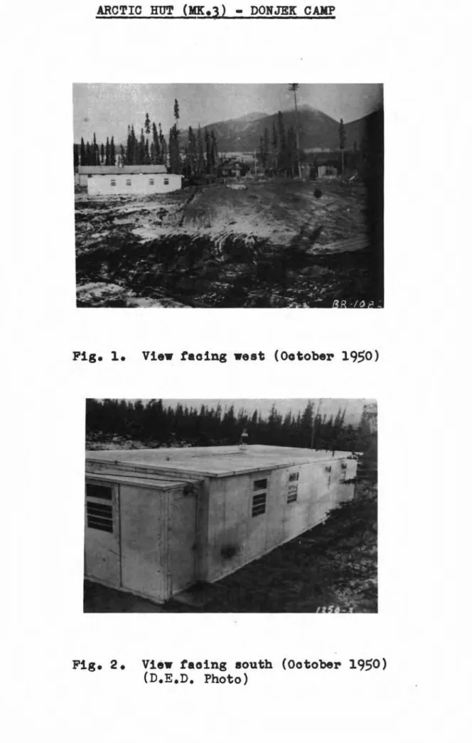
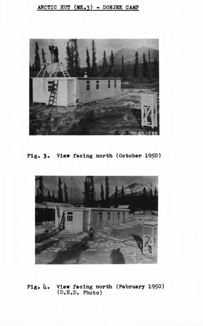
Erection ウゥエセN - Donjek River Camp is a Royal Canadian Engineers' road maintenance camp located on the wooded south-west slope of a mountain overlooking the Donjek River basin at Mile 1130 on' the Northwest Highway System" RQQセ miles northwestof Whitehorse, Yukon Territory. Rle hut was erected at th3 south end of the camp with north-east, south-west orientation facing a large clearing to the south-east (Figso 1 to
4).
The nearest adjacent hut was situated25
to 30 feet to the ョッイエィセ・ウエLand there was virtually no shading from the sun by nearby trees. The ground at the erection site of the hut consisted of' loose sandy silt to a depth of approximately 6 inches" with perma-frost below. There was no grass or other ground cover below tile hut.
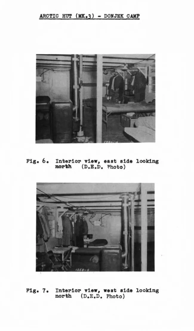
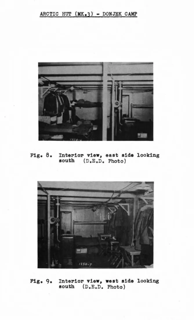
(2) iセエ・イャッイ 。イイセセセ・ュ・ョエN - The prototype hut erected at the Donjek site was divided into two sections by means of an interior partition. The larger section constituting approximately three-quarters of the hut was used as a main barrack room and was arranged to accownodate twelve men. The remaining qUArter served as an instrument room and sleeping quarters for the two non-commissioned officers in charge of the trials. Figure
5
shows the interior layout of the hut, with main entrance at the northern end of the hut and instrument room at the south end. Interior views of the barrack portion of the hut during occupancy are shown in Figs. 6 to 9 inclusive. The 3- by3-inch wooden posts visible in the photographs were not part of the usual hut structure but were Ln atiaL'le d especially for the hea ting and ventilating trials to serve as thermocouple supportso
(3)
Caulkina. - Although 、セウゥァョ・、 for assembly without the need for caulking, ft was found during the Donjek trials that caulking of the roof panels, especially at the ridge flashing at the ends ofopposite panels, was necessary to prevent roof leakage. Floor panels, particularly where they joined the wall panels, were found to require caulking to make the joints weatherproofo
HlセI Services. - Except for electrical power, supplied at
60
cycles, single phase, 110-220 volts by the camp diesel-driven generator,bher-e wer-e no services provided to the Donjek hut. Lavatory, shower and toilet facilities along with laundry equipment were in a special hut elsewhere in the camp.
(5) .Heating equ.iEment. - The main equipment i'or heating the hut was
a single oil-fired BーッエMエセBGー・B space heater wi th a domestic circulator cabinet (CoLeman rv:ode1
s-55)
located approximately in the c entir-e ofthe hut and equipped with a fuel tank of 5-gallon (U.S.) capsci.ty,
a float-type fuel regulator with eight-position dial (off, low, 1, 2,
3,
セNL5,
high), and a 6-inch smoke pipe connected to the r-ear- of the heater by an elbow and terminating in a6-
to 7-inch transition piece at the 7-inch opening of the roof' "jack". Manufactul"'el"d s spe cLf'Lcatdons for the space heater were as follows:-
;;
-Over-all Size (ino) ffeigfit Width' Depth
40 1/2
30
38
1/4
Height to Cen tr-e of Vent Outlet (in. )30 3/4
Fu..el Bu.rninZ
Rate qオ。イエセウ Der houpAt 10"17 At-high Aver-age
1/3
Btu output
per hour
55,000 Aocessorles to the heater included the following:
(a) an automatic draft regulator Lns bsLl.e d in the 6-inch
smoke pipe at approximately
5
feet from the floor; (b) automatic fuel control, used as an alternative tomanual operation of the fuel regulator, whereby on heat demand of the electric thermostat tlle fuol vnlve
is repositioned by an electric relay from a "pilot flame" setting to the setting previously established manually on the fuel r-egulator dial, and on satisfaction of the thermostat the fuel valve reverts to the low or pilot position;
(c) a circula ting fan, loca ted under the heat tre.nsfer surfaces of the heater, driven by a 1/40-h.p. 110-volt 60-cycle motor and having a rated capacity of 18,000
cubic feet of warm ai l l per hour, by which some of
tr...
eheated air is drawn downward and discharged into tbe room horizontally through a grille a few inches above floor level.
(6) Ventilation Equipment. - Ventilation of the'hut was by natural forces only, without the use of fans. The main provision for air exhaust Vias in the special metal roof "jack" (Fig. 10) in which "an 11 1/4-inoh square opening concentric with the 7-inch smoke outlet
served as a roof vent, passing through the roof and "terminating in a metal COWling for proteotion against precipitation. For air supply a 4-inch diameter hole was provided in the floor 、ゥイ・」エャセM below" the heater. Both of these openings could be closed from inside the hut by metal oovers. For additional or alternative ventilation the openable portion of the windows could be used. Thus various combi-nations of ventilation arrangement were possible, from a condition where all vents and windows were open, to a "buttoned up" condition
in which the only ventilation other than infi.ltration and exfiltration through cracks was by exhaust of combustion air and draft regulator air up the smoke pipe.
In an attempt to reduce the ventilation rate below that"
normally required to control odours in the hut, and thereby to reduce the heat loss due to ventilation, a portable odour adsorber was used. This odour adsorber (Dorex Type SQ Size 14) was of the activated
long with eleotrica11y driven propeller fan. m。ョオセ。」エオイ・イGウ
specifioations give the amount of air purified as
333
cubic feet per minute and the amount of air circulated as 1100 cubio feet per minute. The room volume per unit is given as 4000 oubic feet(average) •
3.
METHODS OF TESTThe trials were planned to obtain maXimtIDl information on the behaviour of the hut under all weather conditions and with the heating and ventilation equipment operated in different ways, that is, using various oombinations of heater accessories and ventilation
openings.
Since dry bulb temperature was the biggest factor in the weather 」ッョ、ゥエゥッョセL the general classification of weather severity was made as follows:
Modevabe Wea ther - Approximately 10°F and above. Moderately Severe Weather - Approximately 10° to -20°F.
Severe Weather - Approximately -20°F and belowo
The various combinations of ventilation openings used for the trials were as follows:
rッッセ Vent Floor Opening Winc1ov7s
Condition 1 closed closed closed
"
2 closed closed openIt
R
open closed olosed"
open open closed"
l
open closed openn open open open
Normal operation of the heating ・アオゥーョセョエ was considered to be manual fuel control with heat distribution by natural convection, since the hut was intended for use in Northern locations where
electric power might not be available. fl18 use of the electric
thermostat for fuel 」ッョエイッャセ the heater circulating fan and the
odour adsorber was to be restricted to special trials, to be compared with the standard trials having the same ventilation arrangement
(condition number). The following suffixes to the condition no. denote the special trials:
Suffix T
=
Thermostat fuel control operating; " F=
Heater circulating fan operating; " A=
Odour adsorber operating.During the trials the room thermostat was used more extensively than originally planned to achieve closer air tiemper-atur-e conta-oL and more stabilized test conditions. Unfortunately the odour adsorber Vias not available until the last trial, so that all the other special
7
-To study the crawl space temperature and its probable effect on permafrost, a short series of trials designated as serios A was run with the per-Lmo tier- of the c r-aw'L space r-entsining open, and thore-after for succeeding trials, ser:ios B, tho perimeter was elosed by the banking up of snow except for a small hole left in the banking to admit fresh air for condi tions
4
and 6 when the floor oponing was in use.The trials were to be of bhr-ee-eday duration each giving two three-day trIals and one non-trial day (Sunday) per week, with
additional non-trial days at the Chr-Ls tara s and New Year's periods. During the trials, however, it was found advisable to reduce the duration of the condition 1 trials to two days each because of the unpleasant atmospheric conditions resulting from the reduced
ventialtion.
The schedule of trials as conducted was as shown in Table I. Each trial day was considered as beginning at 0800 hr. on the date of the trial and continuing until the following day at 0800
hr.
4.
INSTRUMENTATI01T AND MEASUREMENTS(a) Meteorological Data
During the heating and ventilation trials of the Arctic Hut (rlP.tr.3) the following meteorological da ba were ob ba Lnede
Outside air (dry bulb) temperature; Outside air relative humidity;
Wind velocity and direction; Depth of snow cover on roof;
General weather observations.
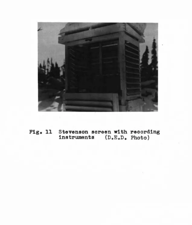
(1) Outside air (dry bulb) temEerature was continuously recorded by means of a single pen thermograph located in a Stevenson screen
approximately
35
feet to the south of the hut (Fig. 11). The thermo-graph was equipped with a seven-day clock-driven drum, and weeklycharts covering the range -30° to 120°F. Special adjustment of the pen linkage of the ゥョウエイセイイ。・ョエ was made to raise the position of the pen the ・アオゥカ。ャセッヲ 50 Fahrenheit degrees and the temperature scale on each chart was lowered c or-r-espond lng'Ly to cover the range -80° to 70°F.
In addition to the "thermograph, outside air tiemper-at ur-e was recorded by means of a 20-gauge copper-constantan thermocouple
installed in the Stevenson screen and connected to a recording po bon t Lome be r- in the instrument room of the hub ,
TABLE I
SCHED.1LIE_OF trialセ
Serles A. (Ht!t EerimeteIll unbanlcedセ
Trial No!. Condition No.
-
DateA-I 2
25
Oct - 21 Oct'50
A-2 3 - FT 30 Oct - 1 Nov
'50
aMセ
セ
2 Nov - セ Nov'50
A-
6
Nov - Nov,
セッ.."
A-l
E
9
Nov - 11 Nov ',50A- 13 Nov - 15 Nov
'50
Series B. (Hut perimeter banked)
B-1 2 20 Nov - 22 Nov '50
B-2
4
23
Nov -25
Nov'50
B-1
3
27
Nov -29
Nov'50
B-4
3 -
T30
Nov - 2 Dec'50
B-5
3
4
Dec -6
Dec '50B-o
4
7
Dec -9
Dec'50
B-7
.5
11 Dec - 12 Dec'50
3-8 1
13
Dec -14
Dec'50
B-9
6
15
Dec -16
Dec'50
B-I0 2 18 Dec - 20 Dec '50
B-l1
4
21 Dec - 23 Dec'50
B-12
3
27
Dec.-29
Dec'50
B-13 3 - T 3 Jan -
5
Jan 151B-14
:3
8 Jan - 10 Jan 151
bMャセ
4
11 Jan -13
Jan'51
B-I0
5
15 Jan - 17 Jan'51
B-17
b
18 Jan - 20 Jan '51 B-18 1 - T 23 Jan - 2h. Jan'51
B-19 2 - T 25 Jan -26
Jan 151 B-204 -
T 29 Jan -31
Jan'51
B-213 -
T 1 Feb -3
Feb '51 B-223 -
FT5
Feb -7
Feb'51
B-233 -
T8
Feb - 10 Feb'51
B-2h4 -
T 12 Feb -14
Feb'51
B-255 -
T15
Feb - 17 Feb '51 B-20b -
T 19 Feb - 21 Feb'51
B-27 2 - T 22 Feb - 24 Feb'51
B-283 -
FT26
Feb - 28 Feb'51
B-293 -
T1
Mar -3
Mar'51
B-304 -
T5
Mar -7
Mar'51
B-31
5 -
T8
Mar - 10 Mar GセQ B-32b
-
T 12 Mar -14
Mar'51
B-33
6 -
T15
Mar -17
Mar'51
B-34
1 -
T19
Mar - 20 Mar'51
B-35 2 21 Mar - 23 Mar'51
B-30
5
26
Mar -28
Mar'51
B-37
2 29 Mar - 31 Mar'51
B-38
1 - TA 2 Apr -3
Apr'51
This schedule gave a total of 125 trial days and
36
non-trial days over the 161-day period from 25 October1950
to3
April 195109
-A mercury-in-g1ass Labor-ator-y thermometer was a Lao used in the Stevenson screen for cnlibra tion of the ther:llogl"aph..
Average outside air temperatures for each trial day, as c ompube d from the recording potentiometer readings, .are given in the table, Appendix A,and appear as Item 1. セセ・ケ are also given in graphical form in Fig. 12. 'l1J.18 highest average ove r the trial period was
35°P (19
March) while the lowest was-49°P (IS
Jan). The mean of the daily averages for the l61-day trial period was approxirootely -lOoP.Daily maxdrnum and minimum outside air temperatures (Iterl)::; 2 and
3
respectively in the table, (Appendix A) show the cxbr-emehigh and low temperatures for the trial period to be
48°F (19
March) and-54°F
(15
and16
Jan).. Degree days on a
65°F
base (Itenl AセI show a variation over the trial period from30 (19
Qセイ」ィI to114
(15
Jan) per day.(2) Outslde air relative humidltx was obtained by means of a single
pen hygr-ogr-aph of the hair-actua ted type Locatad in the samo
Stevenson screen as the bher-mogr-aph , The hygr-ogr-aph was equipped with a seven-day clock driven dr-um, and uti1:tzed weekly char-be
covering the range 10 to 100 per cent rela tive humf.ddエセW e The
instrmnent was calibrated against a sling psychronleter at approximately 70 per cent R.H. at the beginning of the trial period.
Records of outside relative hruuidity (Itom
5,
Appendix A)are incomplete since the outside hygrograph was· inoperative from
25
Oct. to19
Nov. However, during the operative period 20 Nov. to31
March, the average daily outside relative humidity, based on hourly readings, varied from a maximwn of 100 per cent (20, 21 and 22 Nov.)to a minlmmn of
55
per cent(26
March). rna variation in dailyaverage is ShOVlIl in the curve for average outside air relative hmnidity
in Fig. 12.
(3)
Wind speed and direction were continuously recorded by meansor
an anemovane and anemograph-; The three-cup type anemovane was
mounted on a twelve foot mast at the south-west end of the llUt roof (Fig.
3)
and connected by the necessary wiring エィイouセャ a hole in the roof to the anemograph on a table in the instrument room of the hut. The anemograph was the standard three-pen type with north-30utrl and east-west directional pens and a velocity pen, all pens operating through battery-operated relays at intervals of one nlile of wind. Charts were of the RlセMィッオイ type and were driven by a seven-day clock driven drum.Tne average wind speed (Item
6,
Appendix A) based on daily anemograph charts1.. is plotted in Fig. 12 and var-Led from a maxLmum daily average of Cj.9 m.p.h. (11 Jan) to, a minimum of 0.J.,1- m.n.h.(20 Dec.). The over-all mean for the lol-day period was 20
8
m.p.h.The maxdrnum wind recorded for anyone-hour period (Item
7,
Appendix A) was16
miles (11 Nov.).Prevailing wind direction (Item
8,
Appendix A) was SE ror approximately38
per cent of the trial ー・イゥッ、セ N for approximately25
per cent, NW for approxima toly 18 per cent rti.'1.d S f'or appr-ox t.mately10 per cent , Genar-aLLy speaking the higher speed winds wer-e I'r-orn
the ャセv in colder weather and from the SE in milder weathcro
(4) Depth of snow COV6.P on ...roo..:s was measured as a rough aver-age
over the talat roof sur-race , by means of a wooden stake mounted near the south-west end of the roof and graduated in inches from the
roof surface (Fig.
13).
Readings were taken daily, and are contained in AppendixA
as Item9.
Variations in the average depth of snow cover on the roof are shown in the graph in Fig. 12 the maxlmum average depth for the trial period, and for the winter 1950-51, being
9
inches (2 Feb.).(5)
qencral weather ッ「ウセイカ。エゥッョウ were Inade at least once a day, andmor-e often when appr-ec Lab'Le changes occurred. These consistod of visual observations of sky, clouds, sunshine, and precipitation, made in accordance with the following olassifications:
SIg and Clouds Clear
%
Cloud Light Overcast Heavy Overoast Haze (Clear) (-%Cl.)(L.O/C)
(H.O/c)
(H) Light Snow Heavy Snow (Lt. Bn , ) (H. Sn.)Visual observations of general weather conditions such as
sky, degree of overcast, and percentage cloud are given in Appendix A under Item 100 Of the
V+5
days during whioh observations weremade, approximately
40
per cent were clear and40
per cent overcas·t, the overoast varying equally between light and heavyo For theremainder, except for
9
days of hazy conditions, the sky was par'tly cloudy, usually about 50 per oantoPrecipitation (Item ll,Append1.x A) occurred in the form of snow on 21 days of the trial period, the ュ。クゥュセセ snowfall for any one snowfall being
4
inches(30
Nov. to 2 Dec.). No rain was recorded during the123
days of observations.(b) Environment
To assess properly the ・ョカゥイッイイセ・ョエ。ャ conditions provided by
tho Arct;ic hut
(Mko3)
the :following characteristics were determinedby measurement or observation:
Room air (dry blub) temperatures; Panel surface temperatures;
Room air relative hur1idity; Ventilation rate;
- 11 ....
(l) Room air ( dry bulb) borroor-a-..r,.,--.-'_..._ ...'--.,...,._'_..⦅セNiNNLM _ _NMNMNセ⦅セ ...NNNNNNMNセLNM ...セ」NLN⦅ • ._ _.tUl'110 S....,r-- ...--.-.?-...,., - To 0b-c8in the air- tori2D02?aJ,; tiuz-e
distribu'i;ioi1 t;llx'OU[;l1out; t110 mrc , «(I.:...y ....bulb tGmpora"turos 1-.TOrO r-ecor-ded by the usa of tihor-mocoup'Lee located £1t tho 2 .... , 30"", 60... and 9:;>·',::..D.'Jh
elevations above tho f'Loor- at each of ton locations, as shc..n L.:;. Fig.
14.
Location 1 at the 30-inch loval UQS taken 8S a サR」ッョエセッャpoint". At locations 11 セョ、 12 in tho south and north porches
reopootively, tomperatures セッイッ rocordod at tho
e4-inch
level only. Thormocouple loads USE:>d for 1'100111 air tOTnU0l'""3"I; ttU-:>6S r.or-o 2!l_<"'"'rQur:o• セ ...coppcr-eo onetranban cotton-covored enarcoLl.od nil?O,p oach ーセセゥャGB[I of llir10s baing encase d in a glnss fibre alcova and e::tor:c1in.3 f'r-ori tt.3 thor41o-couplo location through a Gvitch-boord in the ゥョ」エセuゥャゥッョエ イPPQセ to a
recording potentior.:otor. I.IotU1"I;ing of tho bhorrocoupt.oe and 't7irc8 pas ヲ。ッゥャゥエセャBエ・、 by tho uno of
3....
by 3-i11011 vCll l t i c 3 l v.ooc'cn POS"CSorocted at the various locationo (Figoo
6
to9)
to vhicll tho wirec uoro sccurod in place uith insulated ntaplos.The thornooouples uoro COlliiooted エャャャセッオcィ a lliultiplo bar::
5("11tchboard (Fig. 15) to a n'crip-chart typo recol1tdi nG ーッエ」dNエゥッZセZLIエ[Pイ
(Leoda and Nor-bhz-up "specdomax'"L, This 1.7aS a sixteen...po Lrrc in.ct;rument
uith a エ・ョセ」イ。エオイ。 ronge
ot
-80°F to 160op , oporntlng uith Q ッセッᆳ minuto print interval.The snitchboard, havt.ng Q total oapacity of
64
th:'iJ:l:1ocouples, セ。ウ roado up of tvo panels mounted one abov0 th0 other and eachoontaining tuo sota of eight doublo-pole 、ッオ「ャッMエィイッセ 「セゥヲッ 8tJitchos. file uppor sot of eight switohes of both panols Xッ」ッイセ」、。エッ、 エィセ
s!;;.:"GeOll thermooouples of bank Ho. 1 rzhon in tho "up" position (ao
shown in the pho togr-aph}; and in tho "dorm" posi tion tho sixtoon thermocouples of bank No.2. Sim.ilarly tIl':> loner seta of s\7itchos
of both panels wor-e uaod for bank No ..
3
in th3 "up" posiエゥッZNQNNセ andhad ro ser-ve capac!ty rOl" a f'our-th bank
or
ci:;:toon thnramocouplos intho "dorm" position.
Bank No.1, oontaining the thormocouples reading the mor-e important tomporotures rorJc1:c.od connootod to the r-ecor-der- for most of th3 daily tost poriod. Throe timoD daily at 0800, 1600D end
2200 hour-o , banlco Hos0 2 and 3 'Jere or,!bched in eoneocuutvoly fOl"
16 minutos each, to record those tomporaturos of lossor iEportanoe.
The schedule of th3rmooouples usod throughout tho エャB_ャセャウ
uas as shotln in Tabla II.
(i)
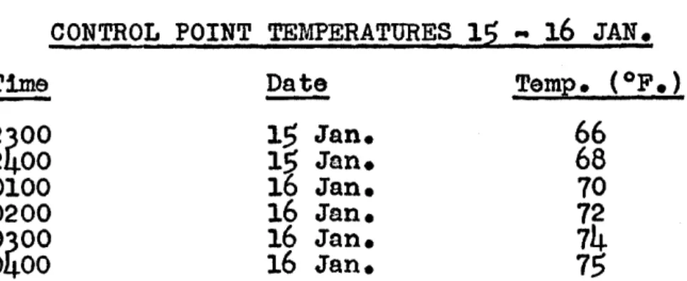
Control point temperaturo. .' . . . Nセ . .6aIiiJ"t&' . .,.,...Tho original trial dirootive oalled for the air tenpOl"'sture
at tho "oontrol pofnb" (30-1nch olevation at locutioll 1) to bo
ュセゥョエqゥョ。、 as olosoly as poosible to 70op o for the duration of the
trialoo セセゥウ nas adhered to for the trialo in tho A ッッセゥッ」 end for tho first four trials in the B sarios.
It
uno ヲッュセ、L hovovor, thatTABLE II
SCHEDULE OF THERMOCOUPLES
Bank No. 1 Bank No. 2 Bank No.3
(normally operating) (0800, 1600 and 2200
hr.)
(0816, 1616 and 2216 hr)No.
Eleva- Looation No. E1eva- Looation NOe E1eva- Locationtion tion tion
(in.) (in.) (in. )
(1)
301
(1)
601
(1)
2 1 (2 ) 30 2 (2 ) 60 2 (2) 2 2(4)
304
(4)
60i
(4)
2a
( )
30セセセ
60( )
2(t)
30t
60 HセI 2セ
( )
30( )
60( )
2(7)
307
(7)
607
(7)
27
(8)
308
(8)
608
(8)
28
(9)
309
(9)
609
(9)
29
(10)セッ
10 (10) 60 10 (10) 2 10 (11)Xセ
11 (11)95
1
(11)95
6 (12 ) 12 (12)95
2 (12 )95
7
(13) Root exhaust (13)95
3 (13 )95
8
vent (a) (14) Root exhaust (14)95
4
(14)
95
9
vent (b) HャセI Outside air HQセI95
S
HャセI95
10(1 )
Crawl space(1 )
Crawl space (1 ) Ground sUl".taceair (100. 3) air (loc. 1) (under' hea ter )
the temperature distribution in the hut was such that in tairly severe weather, even though the control point temperature was
roughly 70°F, the temperature at the level
ot
the upper bunks .wasunoomfortably warm for sleeping. Beginning
4
Dec., theretore, thecondition required to be maintained at the oontro1 point was changed
to allow a reduotion to 65°p. at the oontro1 point for the night
period, (2200 hours to 0800 hours the following da7). Average
oontrol point temperature for eaoh trial day (Item 12, Appendix A) was computed trom the temperature recorder chart records tor thermo-couple 1, bank No.1, where readings were taken apprOXimately every
16 minutes. These are shown graphically in Fig. lb. .
(ii) Temperature distribution
It was origina11,. intended that the tul1 set of
48
tempera-tures recorded at all three periods
ot
bank change, 0800, 1600, and2200 hOurs, be used in the determination or the temperature
13
-the different trial conditions. In analysis of the data, however,
it was found that in many trials the temperature readings at 0800
hours and 2200 hours coincided with ohanges in setting of the fuel
regulator of the heater (under manual control) and changes in setting of the thermostat (under thermostatic control) so that
temperatures in the hut were rising or falling during these periods. Furthermore, at these two periods of the day the hut temperature variations were aggravated by the opening and closing of the doors
of the hut due to the normal movements of the personnel. Consequently
the only full set of
48
temperature readings which could be reliedupon to indicate the true temperature pattern under reasonably
steady conditions were those recorded at 1600 hours
<4
p.mo). These4
p.m. readings when plotted for each trial day using room air(dry-bulb) temperature as abcissa and elevation above the floor as ordinate, resulted in ourves of vortical temperature gradient for
each of the ten room looations. Figures
17
to 34 inolusive havobeen selected as representing typical conditions during days of severe weather, moderately sevare ueather, and moderate woathor for the six basic trial conditions, with the heater fan not in operation
and with the hut perimeter banked. Figura
35
shous typical conditionsfor a day of severe weather with the heater fan in operation and with
hut perimeter banked, while Fig.
36
gives typioal conditions for a dayof moderately severa weather during the period when the hut perimeter
was left unbanked. Tabla III gives the figure numbers, trial conditions
and dates of the selected ourves.
To illustrate the room air temperature distribution both
vertioally and horizontally throughout the hut, the temperature
readings for locations 1 to
7
of the temperature gradient curveshave been replotted to give a series of isothermal lines for vertioal planes along the longitudinal and transverse centre lines of the
barrack room. With room length (and width) as abscissa and height
above floor level as ordinate, isothermallines are given for
too-degree increments in air temperatura. The room air temperature
distribution charts far severa weather trials under condition
3-T
and 3-FT are oontained in Figs.
37
and38.
(2) Panel surface temperatures. - To determine the temperature distrIbution across the interior surfaces of the hut, and thus assess the panels thermally, a series of surface temperatura measurements was made tor typical wall, roof, floor and window
panels. The looations of the typical panels selected are shown in
Fig. 39(a); Fig.
39(b),
(c), (d), and (e) show the details of eachpanel and the locations where surface temperatures were taken. The instrument used for surfaoe temperatures was a contact
pyrometer (Illinois Testing Laboratories - uAlnortf
) with scale range
of 0 to 300°F. and equipped with flexible pyrometer cable with the thermooouple tip designed to be pressed against a flat surfaoe.
The pyrometer reading was checked periodically by placing its thermo-couple tip against the bulb of a standard mercury-in-glass laboratory thermometer 1n air at room temperature.
INDEX OF SELECTED TRIALS
-Figure Trial Type
ot
No. Conditions Date Weather
17 1 - T 23 Jan. Severe
18 1 13 Dec. Mod. Severe
19 1 - T 20 Mar. Moderate
20 2 - T 25 Jan. Severe
21 2 20 Dec. Mod. Severe
22 2 - T 22 Feb. Moderate
セセ
3- T
8 Feb. Severe3 6 Deo. Mod. Severe
25 3
- T
1 Dec. Moderate26
l4.-
T 5 Mar. Severe27
ft.
12 Jan. Mod. Severe28 T 12 Feb. Moderate
29 5
1Z
Jan. Severe30 5 - T 1 Feb. Mod. Severe
31
5
26 Mar. Moderate .32 6 20 Jan. Severe
セ
6 - If14
Mar. Mod. Severe6
- T
21 Feb. Moderate35 3
-FT
6 Feb. Severe36 6 (unbanked)
14
Nov. Mod. SevereSurfaoe temperature readings were taken at approximately 0845 hours on the last day at eaoh trial.
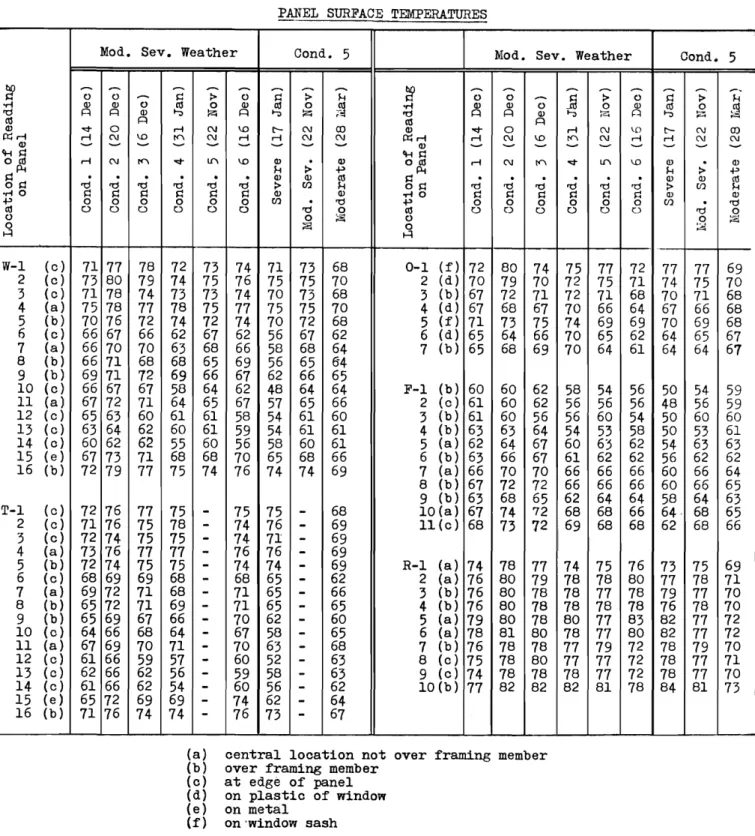
Table IV gives typical panel surface temperatures tor moderately severe weather under trial oonditions 1 to 6 inolusive and also ino1udes temperatures tor trial days under condition 5 for severe, moderately severe, and moderate weather.
W-1 to w-16 inolusive are the wall セ。ョ・ャ surtace temperatures
15
-TABLE IV
PMEL SURFACE TEMPERATURES
Mod. Seve Weather Cond. 5 Mod. Seve Weather Cond. 5
セ
- -
-
- - -
-
-
セ- -
-
-
-
_.
..-. 0 0-
sj :> 0 sj :> H 0 0 ...-セ > 0 Q :> H oM l1> l1> 0 eu 0 l1> eu 0 eu oM l1> l1> 0 0 l1> eu 0 セ ro f=l f=l l1> セ P-:i f=l セ Z [セ ro f=l !=l l1> セ セ r:1 セ :z; eu f=l eu f=l l1> "".t- o r-I N \.D t-- N co l1> "".t- o r-I N \0 t-- N OJrc<r-1 r-I N \.D tc'I N r-I r-I N N rc<,.... ,.... N \.D tc'I N ,.... r-I N N
l1>
- - -
-
-
-
-
- -
l1>- - - - -
-
-
-fHQ fHQ
ッセ ,.... N tc'I "".t- U"\ \.D l1>
.
l1> oeu r-I N tc'I "".t- U"\ \.D l1> l1>H :> .p セ H :> .p §Q ro
.
ro.
ro. . . .
ro ro ro :>l1> enl1> Heu OQsj 'd.
ro. .
ro ro ro.
'd.
:>l1> enl1> セ oMO sj Q Q Q Q Q l1> l1> -MO Q Q sj Q Q セ l1> l1> .p 0 0 0 0 0 0 en ro .p 0 0 0 0 0 0 en.
ro eu 0 0 0 0 0 0 ro 0 eu 0 0 0 0 0 0 'd 0 0 0 セ 0 .9. セ 0 セ 0 ,.,.,. H H W-l (c) 71 77 78 72 73 74 71 73 68 0-1 (f) 72 80 74 75 77 72 77 77 69 2 (c) 73 80 79 74 75 76 75 75 70 2 (d) 70 79 70 72 75 71 74 75 70 3 (c) 71 78 74 73 73 74 70 73 68 3 (b) 67 72 71 72 71 68 70 71 68 4 (a) 75 78 77 78 75 77 75 75 70 4 (d) 67 68 67 70 66 64 67 66 68 5 (b) 70 76 72 74 72 74 70 72 68 5 (f) 71 73 75 74 69 69 70 69 68 6 (c) 66 67 66 62 67 62 56 67 62 6 (d) 65 64 66 70 65 62 64 65 67 7 (a) 66 70 70 63 68 66 58 68 64 7 (b) 65 68 69 70 64 61 64 64 67 8 (b) 66 71 68 68 65 69 56 65 84 9 (b) 69 71 72 69 66 67 62 66 65 10 (c) 66 67 67 58 64 62 48 64 64 F-l (b) 60 60 62 58 54 56 50 54 59 11 (a) 67 72 71 64 65 67 57 65 66 2 (c) 61 60 62 56 56 56 48 56 59 12 (c) 65 63 60 61 61 58 54 61 60 3 (b) 61 60 56 56 60 54 50 60 60 13 (c) 63 64 62 60 61 59 54 61 61 4 (b) 63 63 64 54 53 58 50 53 61 14 (c) 60 62 62 55 60 56 58 60 61 5 (a) 62 64 67 60 63 62 54 63 63 15 (e) 67 73 71 68 68 70 65 68 66 6 (b) 63 66 67 61 62 62 56 62 62 16 (b) 72 79 77 75 74 76 74 74 69 7 (a) 66 70 70 66 66 66 60 66 64 8 (b) 67 72 72 66 66 66 60 66 65 9 (b) 63 68 65 62 64 64 58 64 63 T-l (c) 72 76 77 75-
75 75-
68 10(a) 67 74 72 68 68 66 64· 68 65 2 (c) 71 76 75 78-
74 76-
69 11(c) 68 73 72 69 68 68 62 68 66 3 (c) 72 74 75 75-
74 71-
69 4 (a) 73 76 77 77-
76 76-
69 5 (b) 72 74 75 75-
74 74-
69 R-1 (a) 74 78 77 74 75 76 73 75 69 6 (c) 68 69 69 68-
68 65-
62 2 (a) 76 80 79 78 78 80 77 78 71 7 (a) 69 72 71 68-
71 65-
66 3 (b) 76 80 78 78 77 78 79 77 70 8 (b) 65 72 71 69-
71 65-
65 4 (b) 76 80 78 78 78 78 76 78 70 9 (b) 65 69 67 66-
70 62-
60 5 (a) 79 80 78 80 77 83 82 77 72 10 (c) 64 66 68 64-
67 58-
65 6 (a) 78 81 80 78 77 80 82 77 72 11 (a) 67 69 70 71-
70 63-
68 7 (b) 76 78 78 77 79 72 78 79 70 12 (c) 61 66 59 57-
60 52-
63 8 (c) 75 78 80 77 77 72 78 77 71 13 (0) 62 66 62 56-
59 58-
63 9 (c) 74 78 78 78 77 72 78 77 70 14 (c) 61 66 62 54-
60 56-
62 10(b) 77 82 82 82 81 78 84 81 73 15 (e) 65 72 69 69-
74 62-
64 16 (b) 71 76 74 74-
76 73-
67(a) central location not over framing member (b) over framing member
(c) at edge of panel (d) on plastic of window (e) on metal
T-l to
T-16
inolusive are for a second wall panel. readings for which were begun in the latter part of November.0-1 to 0-7 inclusive are window panel surface temperatures for the positions shown in Fig. 39(c).
F-l to F-ll inolusive are floor panel surfaoe temperatures tor the positions shown in Fig. 39(d).
R-l
to R-lO inolusive are roof panel surfaoe temperaturestor the positions shown in Fig. 39(e).
(3) Roam air relative humidity. - The relative humidity of the room air within the hut was continuously recorded at the "control point"
(looation 1 at 30-ineh elevation). The instrument used was a two
pen portable hygrothermograph (Bendix-Friez) having a card type 30-hour chart with 0° to 110°F. temperature and 0 to 100 per cent
relative humidity scales (Fig.4o). The temperature reading of the
hygrothermograph was periodically checked by the temperatura reading
of the control point thermocouple immediately adjacent to it. The
reading of the relative humidity pen was checked onoe a week by means
of a sling psyohrometer, exoept for the period toward the end of the
trial series when the latter instrument was inoperative.
The daily average relative humidity of the air within the
hut as reoorded at the control point (Item
13,
Appendix A) is shownin graphics1 form in Fig.
16.
The maximum average control pointrelative humidity for anyone day was
40
per oent (20 Mar.) and theminimum was 1) per cent (20 Jan.). The over-all average for the
16l-day trial period was
25.6
per cent. The dew-point temperaturescorresponding to these average relative humidities, assuming
approximately
70°F.
air temperature at the control point, were:max.
45°Fi
min.19°Fi
over-all average33°F. '
<4>
Ventilation rate. - The average ventilation rate of the hut foreach trial day was computed by totalling the air exhausted from the
hut:
Root vent exhaust air;
Air passing through the draft regulator;
Air required by the heater (inoluding excess
air) for combustion.
For conditions 1 and 2 when the roof vent was 」ャッウセ、 the
total ventilation air was given by the last two items only. Since
the temperatures of these three masses of air were not the same,
- 17
P.lICaloulation of the ventilation rate for each trial day was
based on the following formula:
A
c=
VhX'
v
where A
c
=
aVe ventilation rate based on air at 70°F.(air changes per
hr.)
(Item26)
v
=
total air volume (cu. ft. at 70°F.)Vb
=
volume of hut=
6330
cu. ft.X
=
duration of trial (hr.)(Item 25)
The total air volume V for eaoh trial day was computed from the formula:
where
V
=
air volume through roof vent (cu. ft. at10°F.)
y (Item
17)
Vd
=
air volume through draft regulator(ou.
ft.
at 70°F.) (Item 20)v
=
air volume for combustion (cu. ft. at 70°F.)o (Item
24>
(i) Air volume through the roof vent, tor each trial day' was
obtained from
the
formula:where Vy
=
Air volume through roof vent (cu. ft. at70°F.)
(Item
17)
tv
=
Total teet of air (Item15)
A
v =
Free area of opening=
0.592
sq.tt.K
=
Correction factor=
0.5
t
v=
Av. air temp. at roof vent(OF.)
(Item 16)For measurement of total feet of air a vane type anemometer was
mounted in one corner of the square outer casing of the roof vent ョセセ
air entranoe and approximately midway between the outer casing and the
ot 100,000 feet of air and was read five times each trial day at
approximately 0830
hr.,
1230hr.,
1630hr.,
2030hr.,
and 2230 hr.TV/o readings each day, one at the beginning and one at the end of
the trial, would have been sufficient except for the fact that the dial capacity of the instrument was limited and there was soma doubt as to the number of complete revolutions of the instrument
especially during the period 2230 hr. to 0830 hr. From the five
readings and a study of the velooities for the four shorter periods an estimated velooity was determined for the night period and hence
the correct number of complete revolutions established.
The irregularity of the cross-section of the vent opening, ooupled with the fact that the anemonater had to be located near the entrance to facilitate reading of the dials and thus was subject to non-uniform air flow, made it difficult to measure with any accuraoy
the true air flow through the vent. From comparisons of early
trials with roof vent open and closed the calculations showed the anemometer to be giving a much higher reading than the heat balance could justify, indicating that a much greater proportion of the ventilation air was flowing through the anemometer than elseuhare
through the roof vent. A oorrection faotor uas, therefore, established
to be used in the formula equal to 0.5.
Temperature of the air passing out the root vent was given by the average of the recorded readings of two thermocouples oonnected
to the recording potentiometer through bank 1, switches 13 and
14. .
The two thermocouples of 24-gauge copper-constantan, similar to those
used tor room air temperatures were mounted in the lower section
ot
the roof vent, one in each of two corners, and an attempt was made
to shield them against direct radiation from the tlue pipe by
surrounding them with cylindrical matal shields open at both ends.
A flat ring ot sheet metal, approximately 12 inches in outside
diameter was assembled in two sections around the smoke pipe a short
distance below the lower seotion of the roof vent (Fig. 41). This
was done to assist in mixing the higher velocity higher temperature air rising next to the flue pipe with the lower velocity lower
temperature room air, and to give steadier readings of exhaust air
temperature and velocity. Average temperature of the air passing
through the roof vent varied between a maximum
ot
140oF. duringsevera weather and a minimum of 72°F. in moderate weather with an over-all average for the l61-day period of approximately I05°F.
(1i) Air カッャqセ・ through the draft regUlator for each trial
day was determined 1n a simiiar manner to the roof vent air. The
19
-where Vd = Air volume through draft regulator
(cu.
ft. at 70oF.)(Item 20)
f
d
=
Total feet of airAd
=
Free area of opening=
0.117 sq.ft.t
d
=
Av.
air temp.at
draft regulator(OF.)
(Item 18)
(Item
19)
A vane-type anemometer similar to that used for measurement
of air passing through the roof vent was used for determining the
feet of air passing through the draft regulator. Since the draft
regulator presented an irregularly shaped opening, a speoial entranoe
pipe of circular oross-section (Fig.
42)
was fabricated and installedover the frame of the draft regulator using masking tape to seal the
joint against air leakage. The anemometer was mounted in the throat
of this circular opening as shovm in Figs.
8
and9.
Readings of theanemometer were taken three times each trial day.
Temperature of the draft regulator air was given by
thermo-oouple readings of the room air temperatura at the bO-inch leval at
looation
3
which was adjacent to the inlet of the speoial entranoepipe leading to the draft regulator.
(lil)
Air
volume for combustion was determined by calculationbased on the theoretical air required-including excess air as determined by the flue gas analysis. The formula used was as ヲッャQッセSZ
v
=
13.33
AtFdHセ
53
0 ).o
60
+ t·b
where Vo
=
Volume of oombustion air (ou. tt. at 70oF.)(Item 24)
At
=
Total weight of' air, including excess,(lb. per lb. of fuel)
F
=
Fuel oonsumption (U.S. gallons) (Item 21)d
=
Fuel density at60
oF . (lb. per U.S. gallon)(Item 22)
t
b
=
aVe
air temp. at combustion inlet(OF.)
(Item 23)In the determination of the total weight of air (At)' the following formula was used:
=
(3.
04
(N2) vC ) ,At (C0
where (N2)v
=
Nitrogen in flue gas (per oent by vol.) (C02)v
=
Carbon dioxide tlue gas (per oent by vol.)(Co)v
=
Carbon monoxide flue gas (per cent by vol.)C
=
Weight of carbon in fuel (lb. per lb. of fuel)The first three of these factors were determined from the analysis of the flue gas by means of an Orsat type flue gas analyzer,
the percentage carbon dioxide, carbon monoxide and oxygen being
measured directly and the peroontage nitrogen obtained by
sub-traction of the total of these three from 100 per cent. The ueight
of oarbon in the fuel was obtained from the ultimate analysis of the fuel.
Flue gas analyses were made three times during each trial
day along with flue gas temperature readings. Sinoe tha analyses
showed ohanges in proportions of the various gases for different fuel consumption rates, it was neoessary to inter-relate the value of At
with fuel consumption. From a large number of flue gas analyses on
various trial days the value of the total t7eight or combustion air (At) was round and plotted against the fuel oonsumption rate for each
instanoe. From these many points, an average ourve was plotted
(Fig.43) to give the relationship batueen At and ruel consumption
rate. Then tor each increment of fuel consumption for any ona trial
day a value ot At was round from the curve, and the oorresponding
value ot
V
c determined from the エッセオャ。V
o=
13.33 AtFd. Thesummation of these increments ot V
o then gave the total volume of
combustion air for each trial
day.
Plotting these total daily valuesof Vo against the daily fuel oonsumption gave curves shoun in Fig.
44
tor
thetwo
fuels used.(iv) Total measured air カッャオュセL V, for each trial daT, as
obtained from the rormula V
=
Vv + Vd + Vc is givon under Itom25
1nAPpendix A. It varied from approximately 13000 cu.ft. for trial days
under condition 1 with moderate weather to nearly 118,000 ou.ft. for
trial days under condition
5
ttith severe weather. Correspondingmeasured ventilation rates 1n air ohanges per hour shoun as Item
26
in Appendix A varied from
0.09
to0.77.
(5)
Air Qualitz. - No regular measurements were made to assessthe air quailty in the hut during the heating and ventilation
trials Observations of odour intensity セ・イ・ made during
the trials, however, and it was noted that the hut remained comparatively odour free exoept during all oondition 1 trials
21
-arrangements, with all vents and windous olosed, there was a serious accumulation of odours from tobacco, perspiration and oily clothing, so objectionable that condition 1 trials were
reduced to two-day instead of three-day trials. n10 odour
intensity under oondition 2 uas not as great but in most trials
was objeotionable and there uere complaints from the hut oooupants
of "not enough fresh air" particularly for sleeping.
As a health precaution during condition 1 trials the sir
in the hut was sampled and analyzed uith an Orsat apparatus
periodioally about every three hours but there was no undue rise
in the CO2 content of the
air.
For further safety,a
portable COindioator using yellow-to-green oapsules セ。ウ used to sample the air
at various positions in the room near the heater, samples being
taken onoe every hour throughout the trial. No significant amount
of CO was detected.
(e) Heat Balance
A
heat balance セイ a heated structure involves the computationof all the various heat inputs and heat losses of the structure, its occupants, and its heating and ventilating systems and the balanoing
ot
the inputs against the losses to obtain as close an agreement aspossible oonsistent with the accuracy of measurements and oomputations. From the magnitude and proportions of these heat inputs and heat
losses the thermal performance or the overall assembly can then be assessed.
(1)
Total heat input. - The three main components of the total heat inputto the
hut
were: the heat content of the fuel oil burned in theheater, the heat equivalent of electrioal energy used in the hut,
mainly for lighting purposes, and the body heat emitted by the
oocupants of the hut. A fourth oomponent, the heat gain due to solar
radiation through the windous, was neglected in the study of the
thermal performanoe of the hut and 1n the haat balance caloulations.
The radiation exohange of the exterior surface セ。ウ aooounted for only
by using a surface film coefrio1ent which combined convection and
radiation.
Total heat input to the hut was determined for each trial day from the following relationship:
I
= If +Ie
+I
pwhere I
=
Total daily heat input (Btu)If
=
Daily heat input of fuel (Btu)Ie
=
Daily eleotrical heat input (Btu)(Item
33)
(Item
28)
(Item
30)
(1) Heat input of fuel
Fuel heat input was calculated from the equation: If
=
Fdawhere If
=
Daily heat input or fuel (Btu) (Item 28)F
=
Daily fuel consumption (U.S. gallon) (Item 21)d
=
Fuel Density at 60°F. (lb. per U.S. gallon) (Item 22)c
=
Heat content of fuel (Btu per lb.) (Item 27)(a) Fuel oonsUID2ti2n. - The spaoe heater used in the hoating
trials of the Arctio Hut HセcNSI was equipped with a 5-gallon (U.S.)
fuel tank suspendod at the rear of the heater. To measure the fuel
in the tank, a simple float-rod device was fabricated using a cork
float with a vertical rod ーイッエイオ、ャョセ through the oover of the tawe
adjacent to a vertical scale (Fig.
42)
calibrated in tonths of a (U.S.)gallon. Readings of the top of the rod セ・イ・ taken at the beginning
and end of each trial day and before and after each manual filling
ot
the heater tank from the SOO-gallon fuel storage tank outside thehut.
An
8-ounce sampleot
the fuel was drann from the large storagetank immediately after each filling by tank truck, the samples later
being sent to Ottawa laboratories tor ultimate .analysis and for heat
content.
Fuel consumption tor each trial day is given in Appendix A
(Item 21). and for the 161-day trial period is shown graphioally in
Fig.
45.
As is evident from Fig.45
the fuel 011 oonsumption variedfrom a daily maxinum
ot
7.7
u.s.
gallons on15
Jan. to a dailyminimum of 2.15
u.s.
gallons reoorded tor 20 Mar. The total fuelconsumption tor the
158
days when fuel consumption was recorded(inoluding the
35
non-trial days) uaa 698.88U.s.
gallons or an averageof
4.4
u.s.
gallons per 24-hour period.For comparison with the fuel consumption ourve, the curve of
degree-days
(65°F.
base) for the trial period has been included inFig.
45,
and a fairly olose relationship between the two curvos isapparent.
(b) Fuel density. - Density of the fuel 011 used in the heater
(Item 22, Appendix A) was
6.94
ャ「セ peru.s.
gallon trom 25 Oct. to9
Jan. inolusive. From 10 Jan., when the large outdoor fuel tank was
replenished, until the end of the trials on 31 Mar. the density
ot
the fuel oil was 7.10 lb. per U.S. gallon. These density figures
were obtained from the analysis of fuel samples as given in reports reproduoed in Appendix D.