Copyright © 2013 Techno-Press, Ltd.
http://www.techno-press.org/?journal=sem&subpage=8 ISSN: 1225-4568 (Print), 1598-6217 (Online)
Nonlinear thermal buckling behavior of functionally graded
plates using an efficient sinusoidal shear deformation theory
Rabbab Bachir Bouiadjra
1,2, E.A. Adda Bedia
2and Abdelouahed Tounsi
2,31Faculté d’Architecture & de Génie Civil, Département de Génie Civil, Université Sciences et de la Technologie d’Oran, Algeria
2
Laboratoire des Matériaux et Hydrologie, Faculté de Technologie, Université de Sidi Bel Abbes, Algeria 3
Laboratoire des Structures et Matériaux Avancés dans le Génie Civil et Travaux Publics, Université de Sidi Bel Abbes, Faculté de Technologie, Département de Génie Civil, Algeria
(Received August 5, 2012, Revised October 18, 2013, Accepted October 26, 2013)
Abstract. Nonlinear behavior of functionally graded material (FGM) plates under thermal loads is investigated here using an efficient sinusoidal shear deformation theory. The displacement field is chosen based on assumptions that the in-plane and transverse displacements consist of bending and shear components, and the shear components of in-plane displacements give rise to the sinusoidal distribution of transverse shear stress through the thickness in such a way that shear stresses vanish on the plate surfaces. Therefore, there is no need to use shear correction factor. Unlike the conventional sinusoidal shear deformation theory, the proposed efficient sinusoidal shear deformation theory contains only four unknowns. The material is graded in the thickness direction and a simple power law based on the rule of mixture is used to estimate the effective material properties. The neutral surface position for such FGM plates is determined and the sinusoidal shear deformation theory based on exact neutral surface position is employed here. There is no stretching–bending coupling effect in the neutral surface-based formulation, and consequently, the governing equations and boundary conditions of functionally graded plates based on neutral surface have the simple forms as those of isotropic plates. The non-linear strain–displacement relations are also taken into consideration. The thermal loads are assumed as uniform, linear and non-linear temperature rises across the thickness direction. Closed-form solutions are presented to calculate the critical buckling temperature, which are useful for engineers in design. Numerical results are presented for the present efficient sinusoidal shear deformation theory, demonstrating its importance and accuracy in comparison to other theories.
Keywords: functional composites; thermal properties; buckling; plate theory; neutral surface position
1. Introduction
The increased applications of advanced composite materials in structural members have stimulated interest in the accurate prediction of the response characteristics of functionally graded (FG) plates used in situations where large temperature gradients are encountered. Functionally graded materials (FGMs) are designed so that material properties vary smoothly and continuously
through the thickness from the surface of a ceramic exposed to high temperature to that of a metal on the other surface. The mechanical properties are graded in the thickness direction according to volume fraction power law distribution. Since the main applications of FGMs have been in high temperature environments, most of the research on FGMs has been restricted to thermal stress analysis, thermal buckling, fracture mechanics and optimization.
A number of investigations dealing with thermal buckling of functionally graded plate (FGP) had been proposed in the published literature. The nonhomogeneous mechanical properties of the FGP, graded through the thickness, are described by a power function of the thickness variable. Equilibrium equations of a rectangular FGP under thermal loads based on higher order theory were derived by Javaheri and Eslami (2002a). The system of fundamental partial differential equations was established by using the variational method. The derived equilibrium and stability equations for FGPs are identical to the equations for laminated composite plates. A buckling analysis of an FGP under four types of thermal loads was presented. Na and Kim (2004) investigated the three dimensional thermomechanical buckling of an FGP composed of ceramic, FGM, and metal layers. The thermal buckling behaviors of FGM composite structures due to FGM thick- ness ratios, volume fraction distributions, and system geometric parameters were analyzed. The thermal buckling of circular functionally graded plate was studied by Najafizadeh and Heydaru (2004). By assuming that the material properties vary as a power form of the thickness coordinate variable z and using the variational method, the buckling of a functionally graded circular plate under various thermal loads was analyzed. Equilibrium equations of a thick rectangular FGP under thermal loads were derived by Lanhe (2004). Thermal loading of uniform temperature rise and gradient through the thickness was considered. The influences of the volume fraction index and the transverse shear on the thermal buckling temperature were discussed. Bouazza et al. (2010) investigated the thermoelastic buckling of FGP using first shear plate theory. Effects of changing plate characteristics, material composition and volume fraction of constituent materials on the critical temperature difference of FGP with simply supported edges are also investigated. Shariat and Eslami (2005) presented the thermal buckling analysis of rectangular FGPs with geometrical imperfections based on the classical plate theory. Three types of thermal loading as uniform temperature rise, nonlinear temperature rise through the thickness and axial temperature rise were considered. The thermal buckling of a simply supported skew FGP was investigated by Ganapathi (2006) based on the first-order theory. Linear and nonlinear temperature rise across the thickness were taken into account. The effects of aspect and thickness ratios, gradient index and skew angle on the critical buckling temperature difference are studied. Morimoto et al. (2006) presented the thermal buckling analysis of rectangular FGPs subjected to partial heating in a plane and uniform temperature rise through its thickness. The FGM properties of linear thermal expansion and Young’s modulus are changed individually in the thickness direction of the plate with the power law. The effects of material inhomogeneity, aspect ratio, and heated region on the critical buckling temperatures are examined. Thermal buckling of an FGP under the combined effect of elevated temperature and aerodynamic loading was studied by Ibrahim et al. (2007). It is found that the temperature increase has an adverse effect on the FGP flutter characteristics through decreasing the critical dynamic pressure. Decreasing the volume fraction enhances the flutter characteristic. Sohn and Kim (2008) dealt with the stabilities of FG panels subjected to combined thermal and aerodynamic loads. The first-order theory was used to simulate supersonic aerodynamic loads acting on the panels. Matsunaga (2009) presented a higher order deformation theory for thermal buckling of FGPs. By using the method of power series expansion of displacement components, a set of fundamental equations of rectangular FGPs was derived. Kazerouni et al. (2010) presented
thermal buckling analysis of thin functionally graded plates under two cases of thermal loadings as the uniform and non-linear temperature rise cases. Recently, Kettaf et al. (2013) investigated the thermal buckling behavior of functionally graded sandwich plates using a new hyperbolic displacement model.
Neutral surface of functionally graded plate may not coincide with its geometric mid-surface, because of the material property variation through the thickness, leading to bending-extension coupling. Therefore, stretching and bending deformations of FG plate are coupled. Some researchers (Morimoto et al. 2006, Abrate 2008, Zhang and Zhou 2008, Saidi and Jomehzadeh 2009) have shown that there is no stretching-bending coupling in constitutive equations if the reference surface is properly selected. Recently, Bodaghi and Saidi (2011) investigated the buckling of thin FG plates under non-uniform in-plane loading in the framework of the classical thin plate theory. They used the neutral surface concept and showed that the stability equations based on the classical plate theory reduced to the single buckling equation which can be solved by using the power series method straightforwardly.
This paper aims to develop an efficient sinusoidal shear deformation theory based on exact position of neutral surface for thermal buckling analysis of FG plates. This theory is based on assumption that the in-plane and transverse displacements consist of bending and shear components in which the bending components do not contribute toward shear forces and, likewise, the shear components do not contribute toward bending moments. Unlike the conventional sinusoidal shear deformation theory (Zenkour and Mashat 2010), the proposed sinusoidal shear deformation theory contains four unknowns. The material properties are graded in the thickness direction according to the power-law distribution in terms of volume fractions of the constituents of the material. The effective material properties are estimated using a simple power law based on rule of mixture. Since, the material properties of FG plate vary through the thickness direction, the neutral plane of such plate may not coincide with its geometric middle plane (Yahoobi and Feraidoon 2010). In addition, Zhang and Zhou (2008), Ould Larbi et al. (2013), Bouremana et al. (2013), Khalfi et al. (2013), Bousahla et al. (2013) show that the stretching – bending coupling in the constitutive equations of an FG plate does not exist when the coordinate system is located at the physical neutral surface of the plate. Therefore, the governing equations for the FG plate can be simplified. Based on the present theory and the exact position of neutral surface together with the principle of virtual work, the governing equations of the functionally graded plates are obtained. The thermal loads are assumed to be uniform, linear and non-linear distribution through the thickness. The results are compared and validated with the results of previous works which are available in the literature.
2. Problem formulation
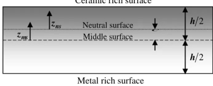
Consider a rectangular plate made of FGMs of thickness h, length a, and width b made by mixing two distinct materials (metal and ceramic) is studied here. The coordinates x, y are along the in-plane directions and z is along the thickness direction. The top surface material is ceramic rich and the bottom surface material is metal rich. For such plates, the neutral surface may not coincide with its geometric mid-surface. The applied compressive force may be assumed to act at the mid-surface of the plate for all the practical purposes, but the in-plane stress resultants act along the neutral surface. The noncoincidence of line of action of stress resultant and applied compressive force results in a couple as schematically shown in Fig. 1. The present study attempts
Fig. 1 The position of middle surface and neutral surface for a functionally graded plate
to investigate the position of neutral surface and the deflection characteristics under in-plane loads. Here, two different datum planes are considered for the measurement of z, namely, zms and zns
measured from the middle surface, and the neutral surface of the plate, respectively (Fig. 1).The volume-fraction of ceramic VC is expressed based on zms and zns coordinates (Fig. 1) as
k ns k ms C h C z h z V 2 1 2 1 (1) where k is the power law index which takes the value greater or equal to zero and C is the distance of neutral surface from the mid-surface. Material non-homogeneous properties of a functionally graded material plate may be obtained by means of the Voigt rule of mixture (Suresh and Mortensen 1998). Thus, using Eq. (1), the material non-homogeneous properties of FG plate P, as a function of thickness coordinate, become
k ns CM M h C z P P z P 2 1 ) ( , PCM PC PM (2)
where PM and PC are the corresponding properties of the metal and ceramic, respectively. In the
present work, we assume that the elasticity modules E, and the thermal expansion coefficient α, are described by Eq. (2), while Poisson’s ratio ν, is considered to be constant across the thickness. The position of the neutral surface of the FG plate is determined to satisfy the first moment with respect to Young’s modulus being zero as follows (Zhang and Zhou 2008)
0 ) ( 2 / 2 /
h h ms ms ms z Cdz z E (3) Consequently, the position of neutral surface can be obtained as
2 / 2 / 2 / 2 / ) ( ) ( h h ms ms h h ms ms ms dz z E dz z z E C (4)2.1 The present sinusoidal shear deformation theory for functionally graded plates
2
h
2
h
C
Metal rich surface Ceramic rich surface
Neutral surface Middle surface ns z ms z
Unlike the conventional sinusoidal shear deformation theory (Zenkour and Mashat 2010), the number of unknown functions involved in the present sinusoidal shear deformation theory based on exact neutral surface position is only four. The theory presented is variationally consistent, does not require shear correction factor, and gives rise to the sinusoidal distribution of transverse shear stress across the thickness satisfying shear stress free surface conditions.
2.1.1 Basic assumptions
Assumptions of the present theory are as follows:
(i) The displacements are small in comparison with the plate thickness and, therefore, strains involved are infinitesimal.
(ii) The transverse displacement w includes two components of bending wb, and shear ws. These
components are functions of coordinates x, y only.
) , ( ) , ( ) , , (x y z w x y w x y w ns b s (5)
(iii) The transverse normal stress σz is negligible in comparison with in-plane stresses σx and σy.
(iv) The displacements u in x-direction and ν in y-direction consist of extension, bending, and shear components. s b u u u U 0 , V v0vbvs (6)
The bending components ub and νb are assumed to be similar to the displacements given by the
classical plate theory. Therefore, the expression for ub and νb can be given as
x w z ub ns b , y w z vb ns b (7) The shear components us and νs give rise, in conjunction with ws, to the parabolic variations of
shear strains γxz, γyz and hence to shear stresses τxz, τyz through the thickness of the plate in such a
way that shear stresses τxz, τyz are zero at the top and bottom faces of the plate. Consequently, the
expression for us and νs can be given as
x w z f u s ns s ( ) , y w z f v s ns s ( ) (8) where h C z h C z z f ns ns ns ) ( sin ) ( (9) 2.1.2 Kinematics
Based on the assumptions made in the preceding section, the displacement field can be obtained using Eqs. (5)-(9) as
) , ( ) , ( ) , , ( ) ( ) , ( ) , , ( ) ( ) , ( ) , , ( 0 0 y x w y x w z y x w y w z f y w z y x v z y x v x w z f x w z y x u z y x u s b ns s ns b ns ns s ns b ns ns (10a) (10b) (10c)
The non-linear von Karman strain–displacement equations are as follows s xy s y s x ns b xy b y b x ns xy y x xy y x k k k z f k k k z ( ) 0 0 0 , s xz s yz ns xz yz z g ) ( (11) where y w y w x w x w x v y u y w y w x v x w x w x u s b s b s b s b xy y x 0 0 2 0 2 0 0 0 0 2 1 2 1 , y x w y w x w k k k b b b b xy b y b x 2 2 2 2 2 2 , y x w y w x w k k k s s s s xy s y s x 2 2 2 2 2 2 , x w y w s s s xz s yz (12a) and h C z dz z df z g ns ns ns ns ) ( cos ) ( 1 ) ( (12b) 2.1.3 Constitutive relations
The plate is subjected to a thermal load T(x, t, zns). The linear constitutive relations are
xy y x xy y x T T Q Q Q Q Q 66 22 12 12 11 0 0 0 0 and zx yz zx yz Q Q 55 44 0 0 (13)
where (x, y, xy, yz, yx) and (x, y, xy, yz, yx) are the stress and strain components,
respectively. Using the material properties defined in Eq. (2), stiffness coefficients, Qij, can be
expressed as , 1 ) ( 2 22 11 Q E zns Q (14a) , 1 ) ( 2 12 E zns Q (14b)
, 1 2 ) ( 66 55 44 ns z E Q Q Q (14c)2.1.4 Stability equations
The total potential energy of the FG plate may be written as
, 2 1
T T dz dydx U x x y y xyxy yzyz xzxz ns (15)The principle of virtual work for the present problem may be expressed as follows
0 0 0 0
dxdy S S k M k M k M k M k M k M N N N s xz s xz s yz s yz s xy s xy s y s y s x s x b xy b xy b y b y b x b x xy xy y y x x (16) where
, ) ( , , , , , , , , / /
h C C h ns ns ns xy y x s xy s y s x b xy b y b x xy y x dz z f z M M M M M M N N N 2 2 1 (17a)
C h C h ns ns yz xz s yz s xz S g z dz S 2 2 / / . ) ( , , (17b)Using Eq. (13) in Eq. (17), the stress resultants of the FG plate can be related to the total strains by sT bT T s b s s s s s s b M M N k k H D B D D B A M M N 0 0 , SAs, (18) where
t xy y x N N N N , , ,
bxy
t b y b x b M M M M , , ,
sxy
t s y s x s M M M M , , , (19a)
T
t y T x T N N N , ,0 ,
bTy
t bT x bT M M M , ,0 ,
sTy
t sT x sT M M M , ,0 , (19b)
t xy y x 0 0 0 , , ,
bxy
t b y b x b k k k k , , ,
sxy
t s y s x s k k k k , , , (19c) 66 22 12 12 11 0 0 0 0 A A A A A A , 66 22 12 12 11 0 0 0 0 D D D D D D , (19d) s s s s s s B B B B B B 66 22 12 12 11 0 0 0 0 , s s s s s s D D D D D D 66 22 12 12 11 0 0 0 0 , s s s s s s H H H H H H 66 22 12 12 11 0 0 0 0 , (19e)
s
t xz s yz S S S , ,
yz,xz
t, s s s A A A 55 44 0 0 , (19f)where Aij, Dij, etc., are the plate stiffness, defined by
ns C h C h ns ns ns ns s s s s s s s s s dz z f z f z z f z Q H D B D A H D B D A H D B D A
2 1 1 ) ( ), ( ), ( , , 1 2 2 2 2 11 66 66 66 66 66 12 12 12 12 12 11 11 11 11 11 , (20a) and
s s s
s s s
H D B D A H D B D A22, 22, 22, 22, 22 11, 11, 11, 11, 11 , (20b)
( )
, 1 2 ) ( 2 2 2 55 44
C h C h ns ns ns s s dz z g z E A A (20c)The stress and moment resultants, Ty
T x N N , bTy bT x M M , and sTy sT x M M due to thermal
loading are defined by
, ) ( 1 ) ( 1 ) ( 2 2
h C C h ns ns ns ns sT x bT x T x dz z f z T z z E M M N (21)The stability equations of the plate may be derived by the adjacent equilibrium criterion. Assume that the equilibrium state of the FG plate under thermal loads is defined in terms of the
displacement components ( 0 0 u , 0 0 v , 0 b w , 0 s
w ). The displacement components of a neighboring stable state differ by ( 1
0 u , 1 0 v , 1 b w , 1 s
w ) with respect to the equilibrium position. Thus, the total displacements of a neighboring state are
1 0 0 0 0 u u u , 1 0 0 0 0 v v v , 0 1 b b b w w w , 0 1 s s s w w w (22) where the superscript 1 refers to the state of stability and the superscript 0 refers to the state of equilibrium conditions.
Substituting Eqs. (11) and (22) into Eq. (16) and integrating by parts and then equating the
coefficients of 1 0 u , 1 0 v , 1 b w and 1 s w
to zero, separately, the governing stability equations are obtained for the shear deformation plate theories as
0 2 0 2 0 0 1 1 2 1 2 1 2 2 1 2 2 1 2 1 2 2 1 2 1 1 1 1 N y S x S y M y x M x M N y M y x M x M y N x N y N x N s yz s xz s y s xy s x b y b xy b x y xy xy x (23)
with
0 2 12 1 2 1 1 2 0 y w w N x w w N N b s y s b x (24)where the terms 0
x
N and 0
y
N are the pre-buckling force resultants obtained as
C h C h ns ns ns y x dz T z E z N N 2 2 0 0 . 1 ) ( ) ( (25)The stability equations in terms of the displacement components may be obtained by substituting Eq. (18) into Eq. (23). Resulting equations are four stability equations based on the present refined shear deformation theory for FG plates in contact with two parameters elastic foundation
2
2 0 1 3 66 12 3 1 3 11 1 0 2 66 12 2 1 0 2 66 2 1 0 2 11 y x w B B x w B -y x v A A y u A x u A s s s s s (26a)
2
2 0 1 3 66 12 3 1 3 22 2 1 0 2 22 2 1 0 2 66 1 0 2 66 12 y x w B B y w B y v A x v A y x u A A s s s s s (26b)
2
2
2
0 2 4 1 1 4 22 2 2 1 4 66 12 4 1 4 11 4 1 4 22 2 2 1 4 66 12 4 1 4 11 N y w D y x w D D x w D y w D y x w D D x w D b b b s s s s s s s (26c)
2
0 2 2 2 2 2 1 2 1 2 44 2 1 2 55 4 1 4 22 2 2 1 4 66 12 4 1 4 11 4 1 4 22 2 2 1 4 66 12 4 1 4 11 3 1 0 3 22 2 1 0 3 66 12 2 1 0 3 66 12 3 1 0 3 11 N y w A x w A y w H y x w H H x w H y w D y x w D D x w D y v B y x v B B y x u B B x u B s s s s s s s s s s s b s b s s b s s s s s s s (26d)4. Trigonometric solution to thermal buckling
Rectangular plates are generally classified in accordance with the type of support used. We are here concerned with the exact solution of Eq. (26) for a simply supported FG plate. The following boundary conditions are imposed for the present efficient sinusoidal shear deformation theory at the side edges
0 1 1 1 1 1 1 1 0 s x b x x s s b N M M y w w w v at x0 a, , (27a) 0 1 1 1 1 1 1 1 0 s y b y y s s b N M M x w w w u at y0 b, . (27b)
boundary conditions
1 1 1 1 1 1 1 1 1 0 1 0 ) sin( ) sin( ) sin( ) sin( ) cos( ) sin( ) sin( ) cos( m n smn bmn mn mn s b y x W y x W y x V y x U w w v u (28) where 1 mn U , 1 mn V , 1 bmn W , and 1 smnW are arbitrary parameters to be determined and m /a and
b n /
. Substituting Eq. (28) into Eq. (26), one obtains
K
0, (29) where
denotes the column
t smn bmn mn mn V W W U1 , 1 , 1 , 1 (30)and
K is the symmetric matrix given by
44 34 24 14 34 33 23 13 24 23 22 12 14 13 12 11 a a a a a a a a a a a a a a a a K , (31) in which
2
66 2 11 11 A A a
12 66
12 A A a 0 13 a ] ) 2 ( [ 12 66 2 2 11 14 s s s B B B a
2
22 2 66 22 A A a 0 23 a ] ) 2 [( 22 2 2 66 12 24 s s s B B B a
4 0 2 0 2
22 2 2 66 12 4 11 33 D 2(D 2D ) D Nx Ny a
4 0 2 0 2
22 2 2 66 12 4 11 34 2( 2 ) x y s s s s N N D D D D a
2 0 2 0 2
44 2 55 4 22 2 2 66 12 4 11 44 2( 2 ) x y s s s s s s N N A A H H H H a (32)By applying the static condensation approach to eliminate the coefficients associated with the in-plane displacements, Eq. (29) can be rewritten as
0 0 2 1 22 12 12 11 K K K K T (33) where
22 12 12 11 11 a a a a K ,
24 14 12 0 0 a a K ,
44 34 34 33 22 a a a a K (34a) 1 1 1 mn mn V U , 1 1 2 smn bmn W W (34b) Eq. (33) represents a pair of two matrix equations
K11 1 K12 2 0 (35a)
12 1
22 2 0K
K T (35b) Solving Eq. (35a) for 1
and then substituting the result into Eq. (35b), the following equation is obtained 0 2 22 K (36) where
44 43 34 33 12 1 11 12 22 22 b a a a K K K K K T (37a) and 33 33 a a , a34 a34 34 43 a a , 0 2 24 0 1 14 44 44 b b a b b a a b 2 12 22 11 0 a a a b , b1a14a22a12a24, b2 a11a24a12a14 (37b) For nontrivial solution, the determinant of the coefficient matrix in Eq. (36) must be zero. This gives the following expression for the thermal buckling load34 44 33 2 34 44 33 2 2 0 0 2 1 a a a a b a N Nx y (38)
4.1 Buckling of FG plates under uniform temperature rise
The plate initial temperature is assumed to be Ti. The temperature is uniformly raised to a final
value Tf in which the plate buckles. The temperature change is ΔT=Tf−Ti. Using this distribution
of temperature, the critical buckling temperature change ΔTcr becomes b5 using Eqs. (24) and (38)
33 44 34 2 34 44 33 2 2 1 2 1 a a a a b a Tcr (39a) where
C h C h ns ns ns E z dz z 2 2 1 1 / / . ) ( ) ( (39b)4.2 Buckling of FG plates under linear temperature rise
For FG plates, the temperature change is not uniform. The temperature is assumed to be varied linearly through the thickness as follows
, 2 1 ) ( M ns ns T h C z T z T (40)
where the buckling temperature difference ∆T=TC−TM and TC and TM are the temperature of the
top surface which is ceramic-rich and the bottom surface which is metal-rich, respectively.
Similar to the previous loading case, the critical buckling temperature difference ∆Tcr can be
determined as
) 2 )( ( 2 34 44 33 2 2 2 34 44 33 2 2 1 2 34 44 33 a a a a a a T a b a Tcr M (41a) where
C h C h ns ns ns ns dz h C z z E z 2 / 2 / 2 2 1 1 ) ( ) ( (41b)4.3 Buckling of FG plates subjected to graded temperature change across the thickness
We assume that the temperature of the top surface is TM and the temperature varies from TM,
according to the power law variation through-the-thickness, to the bottom surface temperature TM
in which the plate buckles. In this case, the temperature through-the-thickness is given by
, 2 1 ) ( M ns ns T h C z T z T (42) where the buckling temperature difference ∆T=TC−TM and γ is the temperature exponent (0<
γ<∞)). Note that the value of γ equal to unity represents a linear temperature change across the
thickness. While the value of γ excluding unity represents a non-linear temperature change through-the-thickness.
Similar to the previous loading case, the critical buckling temperature change ∆Tcr becomes by
using Eqs. (25) and (38)
) 2 )( ( 2 34 44 33 2 2 3 34 44 33 2 2 1 2 34 44 33 a a a a a a T a b a T M cr (34a) where
C h C h ns ns ns ns dz h C z z E z 2 / 2 / 3 2 1 1 ) ( ) ( (34b)5. Results and discussion
In order to obtain the numerical results, an Al/Al2O3 functionally graded plate composed of
Aluminum and Alumina is considered. The Young modulus and coefficient of thermal expansion for Aluminum are EM=70GPa, αM=23.10−6/°C and for Alumina are EC=380GPa, αC=7.4−6/°C,
respectively. The Poisson’s ratio of the plate is assumed to be constant through the thickness and equal to 0.3.
For the linear and non-linear temperature rises through the thickness, the temperature rises 5 °C in the metal-rich surface of the plate (i.e., Tm=5°C).
5.1 Comparative studies
In order to demonstrate the accuracy of the present closed-form exact solution, some comparisons of the present results with those available in the literature has been carried out. In Tables 1 and 2, the plate under uniform temperature rise is considered and the critical buckling temperature change obtained from present efficient sinusoidal shear deformation theory have been compared with those reported by Javaheri and Eslami (2002b) based on both higher plate theory (HPT) and the classical plate theory (CPT), and Zenkour and Mashat (2010) based on sinusoidal plate theory (SPT). From the results presented in Tables 1 and 2, it is observed that results have a good agreement.
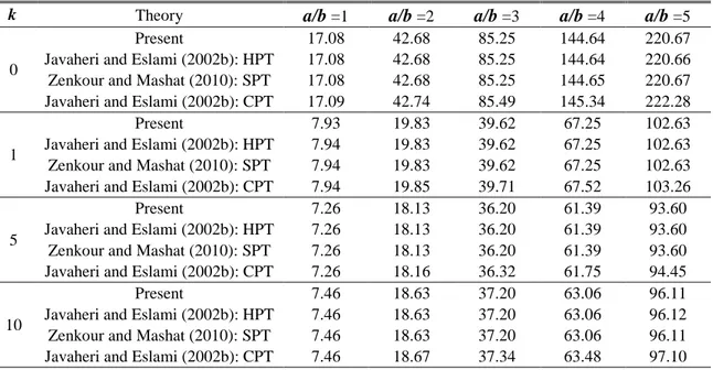
Table 1 Critical buckling temperature of FG plate under uniform temperature rise for different values of power law index k and aspect ratio a/b with a/h=100
k Theory a/b =1 a/b =2 a/b =3 a/b =4 a/b =5
0
Present 17.08 42.68 85.25 144.64 220.67 Javaheri and Eslami (2002b): HPT 17.08 42.68 85.25 144.64 220.66 Zenkour and Mashat (2010): SPT 17.08 42.68 85.25 144.65 220.67 Javaheri and Eslami (2002b): CPT 17.09 42.74 85.49 145.34 222.28
1
Present 7.93 19.83 39.62 67.25 102.63
Javaheri and Eslami (2002b): HPT 7.94 19.83 39.62 67.25 102.63 Zenkour and Mashat (2010): SPT 7.94 19.83 39.62 67.25 102.63 Javaheri and Eslami (2002b): CPT 7.94 19.85 39.71 67.52 103.26
5
Present 7.26 18.13 36.20 61.39 93.60
Javaheri and Eslami (2002b): HPT 7.26 18.13 36.20 61.39 93.60 Zenkour and Mashat (2010): SPT 7.26 18.13 36.20 61.39 93.60 Javaheri and Eslami (2002b): CPT 7.26 18.16 36.32 61.75 94.45
10
Present 7.46 18.63 37.20 63.06 96.11
Javaheri and Eslami (2002b): HPT 7.46 18.63 37.20 63.06 96.12 Zenkour and Mashat (2010): SPT 7.46 18.63 37.20 63.06 96.11 Javaheri and Eslami (2002b): CPT 7.46 18.67 37.34 63.48 97.10
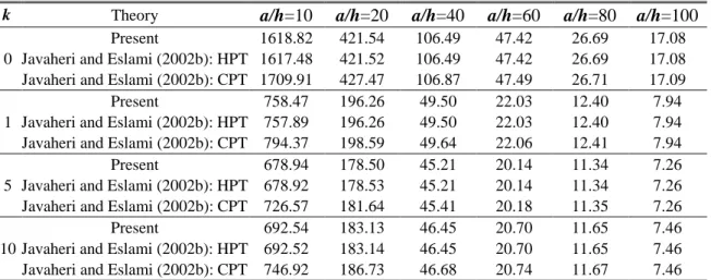
Table 2 Critical buckling temperature of square FG plate under uniform temperature rise for different values of power law index k and side-to-thickness ratio a/h
k Theory a/h=10 a/h=20 a/h=40 a/h=60 a/h=80 a/h=100
0
Present 1618.82 421.54 106.49 47.42 26.69 17.08 Javaheri and Eslami (2002b): HPT 1617.48 421.52 106.49 47.42 26.69 17.08 Javaheri and Eslami (2002b): CPT 1709.91 427.47 106.87 47.49 26.71 17.09 1
Present 758.47 196.26 49.50 22.03 12.40 7.94 Javaheri and Eslami (2002b): HPT 757.89 196.26 49.50 22.03 12.40 7.94 Javaheri and Eslami (2002b): CPT 794.37 198.59 49.64 22.06 12.41 7.94 5
Present 678.94 178.50 45.21 20.14 11.34 7.26 Javaheri and Eslami (2002b): HPT 678.92 178.53 45.21 20.14 11.34 7.26 Javaheri and Eslami (2002b): CPT 726.57 181.64 45.41 20.18 11.35 7.26 10
Present 692.54 183.13 46.45 20.70 11.65 7.46 Javaheri and Eslami (2002b): HPT 692.52 183.14 46.45 20.70 11.65 7.46 Javaheri and Eslami (2002b): CPT 746.92 186.73 46.68 20.74 11.67 7.46 Table 3 Critical buckling temperature of FG plate under linear temperature rise for different values of power law index k and aspect ratio a/b with a/h=100
k Theory a/b=1 a/b=2 a/b=3 a/b=4 a/b=5
0
Present 24.17 75.37 160.51 279.30 431.34 Javaheri and Eslami (2002b): HPT 24.17 75.37 160.50 279.29 431.33 Zenkour and Mashat (2010): SPT 24.17 75.37 160.51 279.30 431.34 Javaheri and Eslami (2002b): CPT 24.19 75.49 160.99 280.68 434.57
1
Present 5.51 27.82 64.93 116.74 183.11
Javaheri and Eslami (2002b): HPT 5.51 27.82 64.93 116.74 183.11 Zenkour and Mashat (2010): SPT 5.51 27.82 64.93 116.74 183.11 Javaheri and Eslami (2002b): CPT 5.52 27.86 65.11 117.25 184.30
5
Present 3.89 22.60 53.70 97.07 152.51
Javaheri and Eslami (2002b): HPT 3.89 22.60 53.71 97.07 152.51 Zenkour and Mashat (2010): SPT 3.89 22.60 53.70 97.06 152.50 Javaheri and Eslami (2002b): CPT 3.89 22.65 53.92 97.69 153.97
10
Present 4.36 24.16 57.06 102.89 161.46
Javaheri and Eslami (2002b): HPT 4.36 24.16 57.06 102.90 161.47 Zenkour and Mashat (2010): SPT 4.36 24.16 57.06 102.89 161.46 Javaheri and Eslami (2002b): CPT 4.37 24.23 57.32 103.64 163.20
Another comparative study for evaluation of critical buckling temperatures between the presented theory based on exact neutral surface position and analytical solution developed by Javaheri and Eslami (2002b) based on HPT, and by Zenkour and Mashat (2010) based on SPT, is performed in Tables 3 and 4. The plate here is subjected to a linear temperature rise across the thickness. From the results presented in Tables 3 and 4, it is observed that results have a good agreement.
Furthermore, in Tables 5 and 6, an interesting comparison study of the present theory with the analytical solution developed by Javaheri and Eslami (2002b) based on HPT, and by Zenkour and
Table 4 Critical buckling temperature of square FG plate under linear temperature rise for different values of power law index k and side-to-thickness ratio a/h
k Theory a/h=10 a/h=20 a/h=40 a/h=60 a/h=80 a/h=100
0
Present 3227.36 833.07 202.98 84.84 43.38 24.17 Javaheri and Eslami (2002b): HPT 3224.96 833.03 202.98 84.84 43.38 24.17 Javaheri and Eslami (2002b): CPT 3409.82 844.95 203.73 84.99 43.43 24.19 1
Present 1412.96 358.71 83.46 31.95 13.88 5.51 Javaheri and Eslami (2002b): HPT 1412.02 358.69 83.46 31.95 13.88 5.51 Javaheri and Eslami (2002b): CPT 1480.45 363.07 83.73 32.00 13.90 5.52 5
Present 1160.68 298.70 69.21 26.06 10.91 3.89 Javaheri and Eslami (2002b): HPT 1160.02 298.69 69.21 26.06 10.91 3.89 Javaheri and Eslami (2002b): CPT 1242.03 304.05 69.55 26.13 10.93 3.89 10
Present 1218.63 315.68 73.46 27.82 11.79 4.36 Javaheri and Eslami (2002b): HPT 1218.32 315.67 73.46 27.82 11.79 4.36 Javaheri and Eslami (2002b): CPT 1314.74 322.04 73.86 27.90 11.82 4.37 Table 5 Critical buckling temperature of FG plate under non-linear temperature rise for different values of power law index k and aspect ratio a/b, and temperature exponent γ with a/h=10
k Theory a/b=1 a/b=2 a/b=3
γ=2 γ=5 γ=10 γ=2 γ=5 γ=10 γ=2 γ=5 γ=10 0 Present 4.84 9.68 17.75 11.22 22.45 41.17 20.01 40.03 73.39 Theory 1 4.84 9.68 17.75 11.22 22.45 41.16 20.00 40.01 73.35 Theory 2 4.84 9.68 17.75 11.22 22.45 41.17 20.01 40.03 73.39 Theory 3 5.11 10.22 18.75 12.80 25.61 46.96 25.63 51.26 93.99 1 Present 2.10 4.31 8.19 4.95 10.14 19.25 8.97 18.38 34.87 Theory 1 2.1066 4.31 8.19 4.95 10.14 19.24 8.96 18.38 34.86 Theory 2 2.1068 4.31 8.19 9.95 10.14 19.25 8.97 18.38 34.87 Theory 3 2.20 4.52 8.58 5.53 11.35 21.53 11.09 22.73 43.12 5 Present 1.59 2.84 4.99 3.64 6.51 11.43 6.36 11.36 19.93 Theory 1 1.59 2.85 5.00 3.65 6.52 11.44 6.37 11.38 19.97 Theory 2 1.59 2.84 4.99 3.64 6.51 11.43 6.36 11.36 19.93 Theory 3 1.70 3.04 5.35 4.28 7.65 13.43 8.58 15.33 26.90 10 Present 1.67 2.88 4.77 3.79 6.53 10.80 6.53 11.24 18.60 Theory 1 1.67 2.88 4.77 3.79 6.53 10.80 6.54 11.25 18.61 Theory 2 1.67 2.88 4.77 3.79 6.53 10.80 6.53 11.24 18.60 Theory 3 1.80 3.11 5.14 4.54 7.81 12.92 9.09 15.64 25.88 Theory 1: Zenkour and Mashat (2010) based on HPT
Theory 2: Zenkour and Mashat (2010) based on SPT Theory 3: Zenkour and Mashat (2010) based on CPT
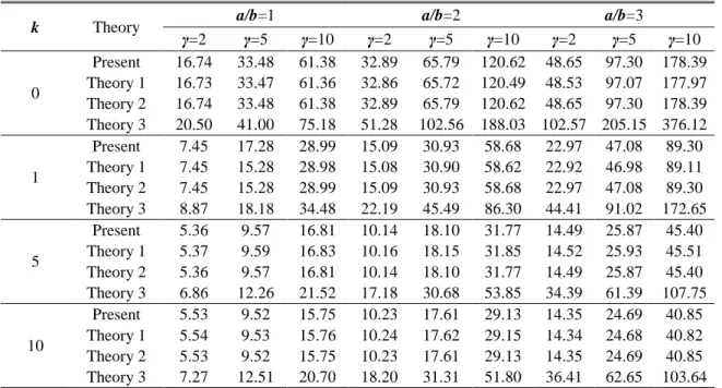
Mashat (2010) based on SPT. Tables 5 and 6 exhibit the critical temperature difference tcr=10−3Tcr
for different values of the aspect ratio a/b, the temperature exponent γ and the power law index k under non-linear temperature loads at a/h=10 and 5, respectively. These tables indicate that our presented results are accurate.
Table 6 Critical buckling temperature of FG plate under non-linear temperature rise for different values of power law index k and aspect ratio a/b, and temperature exponent γ with a/h=5
k Theory a/b=1 a/b=2 a/b=3
γ=2 γ=5 γ=10 γ=2 γ=5 γ=10 γ=2 γ=5 γ=10 0 Present 16.74 33.48 61.38 32.89 65.79 120.62 48.65 97.30 178.39 Theory 1 16.73 33.47 61.36 32.86 65.72 120.49 48.53 97.07 177.97 Theory 2 16.74 33.48 61.38 32.89 65.79 120.62 48.65 97.30 178.39 Theory 3 20.50 41.00 75.18 51.28 102.56 188.03 102.57 205.15 376.12 1 Present 7.45 17.28 28.99 15.09 30.93 58.68 22.97 47.08 89.30 Theory 1 7.45 15.28 28.98 15.08 30.90 58.62 22.92 46.98 89.11 Theory 2 7.45 15.28 28.99 15.09 30.93 58.68 22.97 47.08 89.30 Theory 3 8.87 18.18 34.48 22.19 45.49 86.30 44.41 91.02 172.65 5 Present 5.36 9.57 16.81 10.14 18.10 31.77 14.49 25.87 45.40 Theory 1 5.37 9.59 16.83 10.16 18.15 31.85 14.52 25.93 45.51 Theory 2 5.36 9.57 16.81 10.14 18.10 31.77 14.49 25.87 45.40 Theory 3 6.86 12.26 21.52 17.18 30.68 53.85 34.39 61.39 107.75 10 Present 5.53 9.52 15.75 10.23 17.61 29.13 14.35 24.69 40.85 Theory 1 5.54 9.53 15.76 10.24 17.62 29.15 14.34 24.68 40.82 Theory 2 5.53 9.52 15.75 10.23 17.61 29.13 14.35 24.69 40.85 Theory 3 7.27 12.51 20.70 18.20 31.31 51.80 36.41 62.65 103.64 Theory 1: Zenkour and Mashat (2010) based on HPT
Theory 2: Zenkour and Mashat (2010) based on SPT Theory 3: Zenkour and Mashat (2010) based on CPT
Finally, the present comparative studies show that the results obtained from the proposed method agree well with existing analytical results in the literature which validate the reliability and accuracy of the present analytical approach. It should be noted that the proposed sinusoidal shear deformation theory based on exact neutral surface position involves four unknowns as against five in case of conventional SPT (Zenkour and Mashat 2010) and HPT (Javaheri and Eslami 2002b).
5.2 Parametric investigations
In this section, to examine the effects of different parameters of plate and the type of thermal loads on the critical buckling load parameter a FG plate, the comprehensive results are illustrated in Figs. 2 to 5.
The variation of critical buckling temperatures of Al/Al2O3 FG plates with simply supported edges
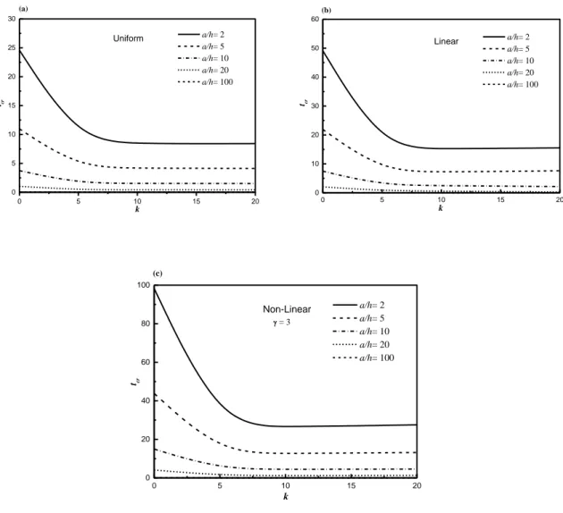
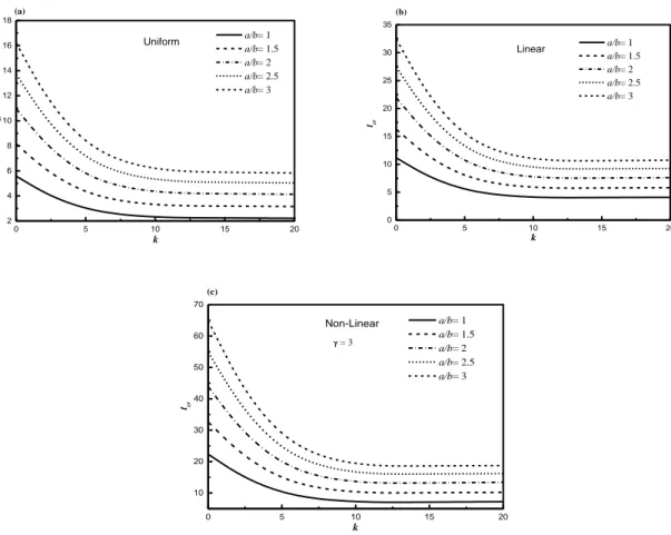
and subjected to uniform, linear and nonlinear temperature rises are shown in Figs. 2 and 3 with respect to the power law index for several values of the side-to-thickness ratio a/h and aspect ratio
a/b, respectively. For the present material properties, the critical buckling temperatures decrease
rapidly within the range of k=0 (ceramic rich) to k=5. As the power law index k becomes larger, all the critical buckling temperatures approach slowly to the values for k =∞ (metallic rich).
It can be also seen from these figures that, regardless of the loading type and the power-law index k, the critical buckling temperature difference tcr decreases as the side-to-thickness ratio a/h
0 5 10 15 20 0 5 10 15 20 25 30 (a) Uniform a/h= 2 a/h= 5 a/h= 10 a/h= 20 a/h= 100 tcr k 0 5 10 15 20 0 10 20 30 40 50 60 (b) Linear tcr k a/h= 2 a/h= 5 a/h= 10 a/h= 20 a/h= 100 0 5 10 15 20 0 20 40 60 80 100 = 3 (c) Non-Linear tcr k a/h= 2 a/h= 5 a/h= 10 a/h= 20 a/h= 100
Fig. 2 Critical buckling temperature difference tcr due to uniform, linear and non-linear temperature rise
across the thickness of FG plate (a/b=2) versus the power law index k for different values of the side-to-thickness ratio a/h
temperature for the ceramic plate is higher than that for the FG plate. This is because the ceramic plate is stronger than the other. The differences between the loading types decrease with the increase of a/h because the plate becomes thin.
The critical buckling temperature change tcr versus the side-to-thickness ratio a/h and the aspect
ratio a/b of FG plates under various thermal loading types is exhibited in Figs. 4 and 5. It can be seen from these figures that, regardless of the loading type, the critical buckling temperature difference tcr decreases as the side-to-thickness ratio a/h increases and it is reduced with the
decrease of the aspect ratio a/b. It is also observed that the tcr increases with the increase of the
0 5 10 15 20 2 4 6 8 10 12 14 16 18 (a) Uniform tcr k a/b= 1 a/b= 1.5 a/b= 2 a/b= 2.5 a/b= 3 0 5 10 15 20 0 5 10 15 20 25 30 35 (b) tcr k Linear a/b= 1 a/b= 1.5 a/b= 2 a/b= 2.5 a/b= 3 0 5 10 15 20 10 20 30 40 50 60 70 = 3 (c) tcr k Non-Linear a/b= 1 a/b= 1.5 a/b= 2 a/b= 2.5 a/b= 3
Fig. 3 Critical buckling temperature difference tcr due to uniform, linear and non-linear temperature
rise across the thickness of FG plate (a/h=5) versus the power law index k for different values of the aspect ratio a/b
4 6 8 10 12 14 16 18 20 0 5 10 15 20 25 30 35 40 45 =10 =5 =2 tcr a/h Uniform Linear Non-Linear
Fig. 4 Critical buckling temperature difference tcr due to uniform, linear and non-linear
temperature rise across the thickness versus the side-to-thickness ratio a/h and for different values of the non-linearity parameter γ (k=5 and a/b=2)
0 1 2 3 4 5 0 5 10 15 20 25 30 35 40 =10 =5 =2 tcr a/b Uniform Linear Non-Linear
Fig. 5 Critical buckling temperature difference tcr due to uniform, linear and non-linear
temperature rise across the thickness versus the aspect ratio a/b and for different values of the non-linearity parameter γ. (k=5 and a/b=10)
6. Conclusions
In the present study, thermal buckling behavior of functionally graded plates subjected to uniform, linear and non-linear temperature rises across the thickness direction has been investigated on the basis of an efficient sinusoidal shear deformation theory. By dividing the transverse displacement into bending and shear components, the number of unknowns and governing equations of the present theory is reduced to four and is therefore less than alternate theories. The mechanical properties of the plate have been assumed to vary through the thickness of the plate as a power function. The neutral surface position for such plates has been determined. A good correlation has been observed between the present results and the available data in literature. Several parametric studies have been performed to show the effects of aspect ratio, plate thickness, thermal loading and also power law index on the critical buckling temperature of functionally graded rectangular plate. Finally, it can be said that the proposed higher order shear deformation theory is not only accurate but also provides an elegant and easily implementable approach for simulating thermal buckling behavior of FG plates. The formulation lends itself particularly well to finite element simulations (Curiel Sosa et al. 2013) and also other numerical methods employing symbolic computation for plate bending problems (Rashidi et al. 2012), which will be considered in the near future.
References
Abrate, S. (2008), “Functionally graded plates behave like homogeneous plates”, Composites Part B: Engineering, 39(1), 151-158.
Bodaghi, M. and Saidi, A.R. (2011), “Thermoelastic buckling behavior of thick functionally graded rectangular plates”, Archive of Applied Mechanics, 81, 1555-1572.
Bouazza, M., Tounsi, A., Adda-Bedia, E.A. and Megueni, A. (2010), “Thermoelastic stability analysis of functionally graded plates: An analytical approach”, Computational Materials Science, 49, 865-870.


![[PDF] Bureautique tsge PDF apprendre Excel | Cours Bureautique](data:image/gif;base64,R0lGODlhAQABAIAAAP///wAAACH5BAEAAAAALAAAAAABAAEAAAICRAEAOw==)