Publisher’s version / Version de l'éditeur:
Vous avez des questions? Nous pouvons vous aider. Pour communiquer directement avec un auteur, consultez la première page de la revue dans laquelle son article a été publié afin de trouver ses coordonnées. Si vous n’arrivez pas à les repérer, communiquez avec nous à PublicationsArchive-ArchivesPublications@nrc-cnrc.gc.ca.
Questions? Contact the NRC Publications Archive team at
PublicationsArchive-ArchivesPublications@nrc-cnrc.gc.ca. If you wish to email the authors directly, please see the first page of the publication for their contact information.
https://publications-cnrc.canada.ca/fra/droits
L’accès à ce site Web et l’utilisation de son contenu sont assujettis aux conditions présentées dans le site LISEZ CES CONDITIONS ATTENTIVEMENT AVANT D’UTILISER CE SITE WEB.
Technical Report (National Research Council of Canada. Ocean, Coastal and
River Engineering), 2019-04-24
READ THESE TERMS AND CONDITIONS CAREFULLY BEFORE USING THIS WEBSITE. https://nrc-publications.canada.ca/eng/copyright
NRC Publications Archive Record / Notice des Archives des publications du CNRC :
https://nrc-publications.canada.ca/eng/view/object/?id=a25939eb-ee31-47ac-bd06-4674b32d6a67
https://publications-cnrc.canada.ca/fra/voir/objet/?id=a25939eb-ee31-47ac-bd06-4674b32d6a67
NRC Publications Archive
Archives des publications du CNRC
For the publisher’s version, please access the DOI link below./ Pour consulter la version de l’éditeur, utilisez le lien DOI ci-dessous.
https://doi.org/10.4224/40000414
Access and use of this website and the material on it are subject to the Terms and Conditions set forth at
Theoretical estimation of floating ice sheet deflection caused by the
motion of a submerged object
Theoretical Estimation of
Floating Ice Sheet Deflection
Caused by the Motion of a
Submerged Object
NRC-OCRE-2019-TR-015
24 April 2019
Hossein Babaei
Ocean, Coastal and River Engineering
© (2019) Her Majesty the Queen in Right of Canada, as represented by the National Research Council Canada.
Cat. No. NR16-271/2019E-PDF ISBN 978-0-660-30312-3
Table of Contents
Executive Summary ... 4
1. Introduction ... 4
2. Modelling Details ... 4
Motion of the ice sheet ... 5
Motion of the fluid ... 6
Governing equations, boundary conditions and solution procedure ... 6
Generation of the shape of the object ... 7
3. Test Matrix and Select Modelling Results ... 9
4. Conclusions and Recommended Future Work ... 13
Theoretical Estimation of Floating Ice Sheet Deflection
Caused by the Motion of a Submerged Object
Executive Summary
The vertical deflection of floating ice sheets subjected to the movements of an underwater object is the subject of the present theoretical study. Steady deflections are estimated based on theories of small deformation of thin plates and potential flow using Fourier and Laplace transform techniques and complex analysis. Deformations are computed for different combinations of object shape, speed, depth, and ice thickness. Depending on the problem condition, deflection extremes range between a few millimeters to tens of centimeters. Ice vertical deflections are reduced by an increase in object depth and ice thickness and with a decrease in object speed. Flexural-gravity waves, resembling a Kelvin wake pattern, are formed when the speed of the object is more than a critical speed. Below this speed, deflections resemble a Bernoulli hump seen in openwater conditions. The report presents a summary and recommendations for future work.
1. Introduction
Freeze-over of natural bodies of water in cold regions is an annual occurrence. Floating ice can interfere with human activities including offshore transportation and offshore fishing. When strong (thick), this ice can bear loads and is occasionally used as roads and construction platforms. Regardless of whether the existence of ice is beneficial, floating ice is deformed when loaded laterally. Examples of this load are the weight of a truck moving or parked on an ice road or pressure loads caused by swimming of an arviq (bowhead whale) under ice. Interestingly, the feasibility of non-contact breaking by fast submarines, in contrast to conventional ice-breaking applications of vessels, is being considered (Economist, 2017).
Measurement and theoretical estimation of ice roads deformations by moving vehicles have been the subject of several past studies. For a list of relevant publications see (Squire et al., 1996). The deformation of ice roads caused by moving trucks has been recently observed from space (van der Sanden & Short, 2017). Whether this is also possible when the moving object is submerged mainly depends on associated deformation magnitudes. The number of studies of ice deformations caused by submerged moving objects is much less than that of over-ice moving vehicles. Examples of relevant studies include (Kozin & Pogorelova, 2008; Părău & Vanden-Broeck, 2011; Kozin & Zemlyak, 2011; Pogorelova et al., 2012). The present report is on the estimation of deformations of a floating ice sheet loaded by the motion of a submerged moving object. The purpose of this estimation is the generation of information needed for identification of the relationship between the deformation magnitude, its pattern and dependence on the shape and speed of the object and its depth. This estimation is through the solution of equations governing the fluid flow and the bending of the ice sheet subject to relevant boundary conditions forming a complete boundary value problem. The present work combines the developments by Kozin & Pogorelova (2008), Pogorelova (2011) and Pogorelova et al. (2012). The report proceeds with a section on assumptions, modelling and solution details, followed by a results and discussion section and ends with a section on conclusions and suggestions for future work.
2. Modelling Details
This section briefly describes the details of the problem and summarizes the modelling assumptions, equations, and solution procedure. The problem is the computation of vertical deflection of an ice sheet with a uniform thickness of ℎ, loaded by the motion of an object with length of 2 and a radius of , moving horizontally with a uniform speed of at a depth of . Figure 1 shows relevant problem parameters. Note that horizontal
coordinates are x and y, and respectively parallel and perpendicular to the object path. The xy plane coincides with the underside of the ice, where the vertical coordinate, z, equals 0. Consult Figure 1 for a diagram. We tackle this fluid-ice interaction problem by the establishment of a relevant boundary value problem
describing the coupled motion of the fluid and the ice sheet caused by the motion of the submerged object. The modelling details of fluid and solid mechanics of the problem are explained separately in this section.
Figure 1. Parameters and geometry of the problem.
Motion of the ice sheet
Small deformation, thin plate theory of plates (Timoshenko & Woinowsky-Krieger, 1959) is adopted for describing the motion of the ice. Conditions for the validity of this theory are as follows:
• The (ice) plate deflection and its derivatives are small. Particularly, the deflection (along z direction) is smaller than the thickness.
• The plate thickness is very small relative to its other two dimensions. This condition is easily satisfied for large continuous ice sheets.
• The middle plane of the plate does not experience any stress. The middle plane is then neutral which means in-plane external loads can be neglected.
• Planes originally normal to the neutral plane remain normal to it after the deformation, which means the resulting shear deflections of the ice plate can be neglected.
• Normal stresses along the thickness are negligible relative to in-plane stresses which means the three-dimensionality of the problem can be neglected. This allows simplification into a two-dimensional problem, i.e., the deflection of ice is only a function of x and y.
In addition to the above, the ice is homogenous, isotropic and geometrical, and material nonlinearities are neglected, i.e., strains are small and the ice behavior is linearly elastic. Answering to the question of how the violation of any of the above conditions impact the estimated ice deflection is extremely difficult since this impact is problem specific. As an example, for a simply supported laterally loaded plate, the deflections are overestimated as they approach and exceed the plate thickness (Melliere, 1969). Note that disregarding of any of above validity conditions leads to problem complexities beyond the scope of this study.
Ice sheet
Motion of the fluid
The ice is deflected because of the motion of the object. To calculate this deflection, the fluid pressure and velocity field created by this motion is needed. The flow away from the immediate vicinity of the object is not highly frictional and rotational. Flows of this nature can be modelled by the potential flow theory (White, 1979). The velocity field of a potential flow is the gradient of a scalar function named the potential function.
Additionally, the pressure field in a potential flow can be estimated by the Bernoulli equation. The potential flow theory is not suitable for the estimation of frictional and rotational flows, which is the case in the thin boundary layer around the moving object; vortices and flow separation, usually associated with non-“streamlined” objects, are not captured either.
Governing equations, boundary conditions and solution procedure
In a Cartesian coordinate system moving with the object, steady-state governing equations and boundary conditions, considering the above assumptions and conditions, are:
∇ − + ℎ = 0 (1a) = − + (1b)
= − (1c) in which , "# and $ , ", %# are respectively, the vertical deflection of the ice mid-surface and the flow potential function, is the pressure acting on the underside of the ice and positive when acting upward, is the density and subscripts & and ' denote ice and water, ( denotes partial derivation, is the gravitational
acceleration and is the flexural rigidity of the ice plate which is equal to , ,-. #)*+ with / and 0 being Young’s modulus and Poisson’s ratio of ice.
Equation (1a) governs the motion of the plate subjected to being the flow pressure on the underside of the ice. Equation (1b) is the linearized version of Bernoulli equation, relating the pressure to the deflection and velocity (the gradient of the potential function is the velocity). The main boundary condition of the problem is equality of the vertical speed of the ice and that of the fluid at the interface. Equation (1c) is imposing this boundary condition in a linearized form. If the problem is only propagation of surface water waves in the absence of ice, this linearization requires that the ratio of wavelength to wave amplitude to be more than 7 (Techet, 2005). Note that since the ice is assumed to be very large in x and y directions, if the ice deflections at “infinity” is finite, the boundary condition on the vertical cross sections of the ice at “infinity” has an insignificant effect on the deflection of the ice in the region of interest. This condition is implicitly satisfied in the solution procedure. Additionally, we are not imposing any velocity boundary condition at any finite depth in the fluid domain. The infinite depth of the domain and equality of the vertical component of the flow velocity at the bottom to zero are both imposed implicitly in the solution procedure.
Kozin & Pogorelova (2008) solved Eqs. (1) for a horizontally moving source-sink system in which the strength of the source is equal to the strength of the sink. The source is at % = − and the sink at % = . The solution provided therein, is mainly based on the Fourier and Laplace transform techniques and reduces to the following double improper integral:
,=1324 4 5: ;:2 -67829,
<=>?2@82-;2 A
B82C-82 D82D;2 E9,cos I,",#EI, (2)
in which non-dimensional parameters of ,, J,, K, ,, ",, and L are respectively NM, JMNC (J is the strength of the source with volume/time dimension), N
OMP (Froude number), M N , "
M N , and
QM+
RSNT. Note that in the derivations
leading to Eq. (2) the inertia of the ice is assumed to be negligible. This assumption is valid when L ≫ V =RW*M
According to Schulkes & Sneyd (1988) work on the modelling of ice roads, neglecting inertia is justifiable when the wavelength of ice deflection is much larger than the ice thickness, in which case the mass of the moving fluid is much more than that of ice (Squire et al., 1996).
It can be mathematically shown that the behaviour of the integrand associated with the integral of Eq. (2) highly depends on whether the object speed is more or less than a value named the critical speed, XYZ [. This value for deep basins is XYZ [= 2 \QM]R+
S^ 2 T
. When the speed of the object is less than the critical speed, the integral is not singular within the integration range, however, when the object speed is more than the critical speed, the integral is singular over curves within the integration. The singularity of the problem is treated via complex analysis and Cauchy's residue theorem. When the integral is singular and it is evaluated for a location in front of the source ( _ 0), the integral can be significantly simplified. However, when ` 0, an additional step in the treatment of singularity is required. Kozin & Pogorelova (2008) briefly explains the integration procedure. In the present work, the integral is evaluated using a combination of MATLAB built-in capability and an in-house developed code in MATLAB using Gauss-Legendre integration technique with 512 integration nodes. Local and global tolerances of integration were set to 10-b.
Generation of the shape of the object
The sink-source pair that was used by Kozin & Pogorelova (2008) to represent the moving object has two main limitations: (1) It cannot reproduce an oval object shape shown in Fig. 1, and (2) a realistic value of J that leads to correct representation of the object is unknown. Additionally, the flow does not intersect with the free surface in reality, but with the present source-sink system, it flows from the source to the sink. The horizontal speed at the interface is however correctly imposed and is equal to . To depict the first limitation, an online potential flow viewer for two-dimensional flows (Potential Flow simulator, 2019) was used. Figure 2 shows streamlines of a 2D sink-source system when J = 1000 c+
d, = 20 e, and = 10 c
d. As seen, the streamlines are not
representative of what is expected by the oval object shown in Fig. 1.
Figure 2. Streamlines of a sink-source system cannot acceptably represent the oval object shown in Fig. 1. The figure is for 2D system associated with J = 1000 cd+, = 20 e, and = 10 cd. The horizontal axis is the x coordinate and numerical value in the figure are in meter.
To lift the two limitations given above, Pogorelova et al. (2012) proposed a new system with two sink-source pairs shown in Figure 3. Approximate object length (2 ), and radius ( ) are imposed by the strength of the sources, which is equal to the strength of sinks, based on the following equation:
J = J (3a) J f g ?1 +Z \1 − h D,#, 2.C^A (3b)
Figure 3. Double sink-source system used in the present report for the representation of the oval shown in Fig. 1.
in which j = k
l and m = P
l. The horizontal distance between the sink and the source is given by the following
equation:
2 1= 2 − 2n (4a)
n fk?1 +Z \]b− h D,#, 2.C+b h D,#, 2.C^A (4b)
This approach significantly improves the generation of the oval object. Figure 3 shows the streamlines for a 2D case for conditions similar to the condition associated with Fig. 2 for an object that is 50 m long with a diameter of 5 m. Note that for this example, according to Eqs. (3) and (4), J and n are 197.1851 c+
d and 1.2525 e.
Figure 4. Significant improvement in the generation of the oval shape of the moving object by the two sink-source pair system. The figure shows streamlines of a 2D system associated with J = 197.186 cd+, = 20 e, and = 10 cd, 2 = 50 e, and = 2.5 e. The horizontal axis is the x coordinate and numerical value in the figure are in meter.
As seen in Fig. 4, this double sink-source approach can acceptably generate the shape of the object. This generation is a close approximation if three conditions are met: (1) j ` 0.3 (the object is slender), (2) m _ j (object radius is less than its depth), and (3) 1
P ≪ (to minimize flow from sources to sinks) (Pogorelova et al.,
2012). For the above example, these conditions are met: j = 0.1 ` 0.3 , m = 0.8 _ j, and 1
P = 0.493 ≪ = 10.
Considering the above approach, the vertical deflection of ice, ,wxwyz, is found by the superposition of the solution of two (single) sink-source systems located at = 0 and = 2 1 by the following equation:
,wxwyz= , , "# − ,{ − 2 1, "| (5)
in which , is given by Eq. (2). This superposition approach is possible because of the linearity of the governing equations of fluid flow and ice deflection, as modelled in the present study.
3. Test Matrix and Select Modelling Results
Vertical deflection of ice was computed for a total of 56 cases consisting of different combinations of object geometry (two objects) and speed, moving depth and ice thickness. Results of the computations were delivered to the client of the study, AstroCom Associates Inc. The test matrix of the computations is given in Table 1.
Table 1. Modelled 56 cases.
Object (length,
diameter) , }~, }•#,
pair, €
Object depth, •, € Object speed, ‚, €
ƒ Ice thickness, „, €
Object 1: (170, 13)
Object 2: (110, 13.5) 30, 40, 65 2.572, 5.144, 10.289 0.25∗, 0.5, 1 With two additional runs: = 60 e, = 15.433 e/‡ , ℎ = 1 e for each object pair.
∗
This thickness is associated with the critical speed, ˆˆ‰Š‹, of 9.451€ƒ.
Numerical values of material properties are: / = 559 Œ•, 0 =,Ž , = 1030c•M+. Gravitational acceleration, , is 9.81dc. Note that since we are neglecting the inertia of the ice plate, the results do not depend on the density of the ice, .
The impact of ice thickness and object depth, speed, and geometry on the deflection of the ice was briefly investigated.
When the thickness of ice is increased, its deflection is reduced. Figure 5 shows deflections on " = 0 for Object 1, of Table 1, when the object depth is 30 e and its speed is 5.144 cd.
Figure 5. The ice deflection is reduced with an increase in the ice thickness. The above curves are for " = 0 and Object 1of Table 1 when the depth is 30 e and its speed is 5.144 c
d.
When the object depth is increased, deflections are reduced. This is shown in Fig. 6 for Object 1 moving with the speed of 10.289 cd.
Figure 6. As expected, an increase in the object depth reduces the deflections. This figure is for Object 1 moving at 10.289 cd under an ice sheet of 0.5 e thick. The above curves are for " = 0.
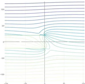
Figure 7 shows the significance of object speed on the deflection pattern of ice. For subcritical speeds, ` XYZ [, the deflection of the ice is concentrated in a region close to the object and no steady wave exists in ice.
For openwater conditions this deflection pattern is occasionally named Bernoulli Hump (Chen, 2005). This is seen is Figs (5) and (6) above where the speeds are subcritical. However, for supercritical speeds, _ XYZ [, flexural-gravity waves, with restoring forces of the flexion of ice and gravity, are formed. This wave pattern resembles Kelvin wake pattern behind an object moving at the interface of two different fluids. When ice thickness is 0.25 e, for the present ice and water properties, the critical speed is 9.451 €
ƒ. Figure 7 is for this ice
Figure 7. Formation of flexural-gravity waves in ice for supercritical speeds. This figure is for Object 1 moving to the right under a 0.25 e thick ice at a depth of 40 e. The above curves are for " = 0. For this condition, approximate wavelength associated with the speed of 10.289 c
d is 62 e.
Figure 8 shows the two-dimensional ice surface deflection for the same ice, object and depth of Fig. 7 for subcritical and supercritical speeds of 5.144 €
ƒ and 10.289 €
ƒ (Figs. 8a and 8b, respectively).
This section ends with a comparison of ice deflection produced by two different objects, Object 1 and Object 2. Figure 9 depicts the effect of object shape for two different object speeds: a subcritical and a supercritical case. Regardless of the speed of the object, the absolute value of deflections extremes caused by Object 2 is larger than that of Object 1. Note that the difference between Object 1 and Object 2 is mainly their length, former being 170 m and latter being 110 m long. The major difference between deflections caused by the motion of Object 1 and Object 2 is on the deflection troughs. The response to the object length strongly depends on the deflection caused by single source pair and the superposition of this deflection with the second single sink-source, see Fig. 2. Depending on the deflection distribution of a single source-sink pair and the spacing between this pair with the second pair, the superimposed deflection of different object could differ. It is expected that deflection extremes generated by objects longer than Object 1 will be very similar to those caused by Object 1.
Figure 8. Two-dimensional vertical ice deflection associated with Fig. 7 for two object speeds of (a) 5.144 m/s, and (b) 10.289 m/s. Bernoulli hump and Kelvin wake patters are seen depending on the object speed. The former for subcritical case, Fig. 8a, and the latter for the supercritical case, Fig. 8b.
b
a
Figure 9. Object 2 generates larger deflections than Object 1. Object 2 is approximately 35% shorter and 4% wider than Object 1.
4. Conclusions and Recommended Future Work
The motion of a submerged object under a floating ice sheet deflects ice if the moving object is close to it. Computation of these deflections is the subject of the present study. Theories of small deformation of thin plates and potential flow are employed in the derivation of governing equations which are solved by Fourier and Laplace transform techniques and complex analyses. The object shape is an oval and is generated by the superposition of two moving sink-source pairs whose spacing and strength is imposed by the object shape and speed. Deflections caused by different conditions including object shape, speed and depth, and ice thickness are computed. Thicker ice, deeper and slower object generate smaller deformations. Flexural-gravity waves form when the object is moving faster than a critical speed which is a function of flexural rigidity of ice and density of the fluid for deep basins.
The present study is expected to capture the main physics involved, and is a reliable first approximation of deflections produced by the motion of submerged object. The present study is however, not applicable when:
(1) Object velocity changes. This is the case for turning, accelerating and decelerating objects. (2) The basin is shallow which is expected to produce larger ice deformations.
(3) Ice thickness is non-uniform and ice floe size is not very large compared with its thickness and the size of the object.
(4) Ice deflections are large compared with the thickness of ice. (5) Object is very fast under thin ice.
(6) Object shape is complex and the flow separation and rotation are dominant.
Future developments could include the extension of the present model, and/or development of new models, to provide solutions applicable to the above conditions.
References
Chen, Y., Feng, J. and Minhui, Z., 2005, July. Detection methods of submerged mobile using SAR images. In Proceedings. 2005 IEEE International Geoscience and Remote Sensing Symposium, 2005.
IGARSS'05. (Vol. 3, pp. 1717-1720). IEEE.
Kozin, V.M. and Pogorelova, A.V., 2008, January. Submarine moving close to the ice-surface
conditions. In The Eighteenth International Offshore and Polar Engineering Conference. International Society of Offshore and Polar Engineers.
Kozin, V.M. and Zemlyak, V.L., 2011, January. Experimental Study on Ice-Breaking Capacity of Flexural-Gravity Waves Caused by Motion of Submarine Vessel. In The Twenty-first International Offshore and
Polar Engineering Conference. International Society of Offshore and Polar Engineers.
Melliere, R.A., 1969. A finite element method for geometrically nonlinear large displacement problems in thin, elastic plates and shells. PhD Dissertation, University of Missouri, Rolla.
‘The quickest way to break the ice is by submarine’, Economist, 12 Apr 2017,
https://www.economist.com/science-and-technology/2017/04/12/the-quickest-way-to-break-the-ice-is-by-submarine, accessed on 14 March 2019.
Van der Sanden, J.J. and Short, N.H., 2017. Radar satellites measure ice cover displacements induced by moving vehicles. Cold Regions Science and Technology, 133, pp.56-62.
Părău, E.I. and Vanden-Broeck, J.M., 2011. Three-dimensional waves beneath an ice sheet due to a steadily moving pressure. Philosophical Transactions of the Royal Society A: Mathematical, Physical and
Engineering Sciences, 369(1947), pp.2973-2988.
Pogorelova, A.V., 2011. Unsteady motion of a source in a fluid under a floating plate. Journal of
applied mechanics and technical physics, 52(5), p.717.
Pogorelova, A.V., Kozin, V.M. and Zemlyak, V.L., 2012. Motion of a slender body in a fluid under a floating plate. Journal of Applied Mechanics and Technical Physics, 53(1), pp.27-37.
Potential Flow simulator, https://potentialflow.com/, retrieved on 21 March 2019.
Techet, A. 2.016 Hydrodynamics (13.012). Fall 2005. Massachusetts Institute of Technology: MIT OpenCourseWare, https://ocw.mit.edu. License: Creative Commons BY-NC-SA.
Timoshenko, S.P. and Woinowsky-Krieger, S., 1959. Theory of plates and shells. McGraw-hill. Schulkes, R.M.S.M. and Sneyd, A.D., 1988. Time-dependent response of floating ice to a steadily moving load. Journal of Fluid Mechanics, 186, pp.25-46.