Publisher’s version / Version de l'éditeur:
ASHRAE Transactions, 96, 2, pp. 373-383, 1990
READ THESE TERMS AND CONDITIONS CAREFULLY BEFORE USING THIS WEBSITE. https://nrc-publications.canada.ca/eng/copyright
Vous avez des questions? Nous pouvons vous aider. Pour communiquer directement avec un auteur, consultez la première page de la revue dans laquelle son article a été publié afin de trouver ses coordonnées. Si vous n’arrivez pas à les repérer, communiquez avec nous à [email protected].
Questions? Contact the NRC Publications Archive team at
[email protected]. If you wish to email the authors directly, please see the first page of the publication for their contact information.
NRC Publications Archive
Archives des publications du CNRC
This publication could be one of several versions: author’s original, accepted manuscript or the publisher’s version. / La version de cette publication peut être l’une des suivantes : la version prépublication de l’auteur, la version acceptée du manuscrit ou la version de l’éditeur.
Access and use of this website and the material on it are subject to the Terms and Conditions set forth at
Fire tower tests of stair pressurization systems with overpressure relief
Tamura, G. T.
https://publications-cnrc.canada.ca/fra/droits
L’accès à ce site Web et l’utilisation de son contenu sont assujettis aux conditions présentées dans le site LISEZ CES CONDITIONS ATTENTIVEMENT AVANT D’UTILISER CE SITE WEB.
NRC Publications Record / Notice d'Archives des publications de CNRC:
https://nrc-publications.canada.ca/eng/view/object/?id=2c351159-e45a-43d1-a3d6-ae855e508180 https://publications-cnrc.canada.ca/fra/voir/objet/?id=2c351159-e45a-43d1-a3d6-ae855e508180
Ser
T H I
N 2 1 d
n,
1 6 9 0
National Research
Consell national
l g g o
1+1
c
BLDG,
ouncil Canada
de recherches Canada
- -
Institute for
lnstitut de
Research in
recherche en
Construction
construction
Fire Tower Tests of Stair Pressurization
Systems with Overpressure Relief
by G.T. Tamura
Preprints from
ASHRAE Transactions
1990, V. 96.
Pt.2
p.p. 10
(IRC Paper No. 1690)
NRCC 32360
NRC-
CISTII R C
L I B R A R Y
APR
25
1991
B I B L I O T H ~ Q U E
I
CNRCI R C
-
I C I I TOn a test4, dans une tour d'expbrimentation incendie de
10
&ages, des
systemes de pressurisation de cages d'escaliers selon divers schbmas
d'utilisation des portes d'escaliers, dans des conditions de non-incendie et
d'incendie, et en 4tb et en hiver. Les quatre systemes en question
comportaient les moyens suivants d'blimination de la surpression
:elimination au moyen de la porte de sortie, dimination
A
l'aide de registres
barombtriques, commande par rbtroaction utilisant une dbrivation de
ventilateur, et commande par rbtroaction employant un ventilateur
A
vitesse
variable. Les essais ont r4vblb que, dans les conditions mentionnbes,
l'utilisation de l'un ou l'autre des syst&mes de pressurisation entrafne en
principe l'envahissement de la cage d'escalier par la fumbe si la porte
d'escalier de lf4tage du feu est ouverte et si celui-ci n'est pas ventilb sur
l'extbrieur. La cage d'escalier n'a pas 4t6 envahie par la fumbe lorsque l'btage
en feu a btb ventilb au moyen d'ouvertures dans le mur extbrieur, mais elle
l'a 6t6 lorsqu'on a ouvert une
nu nlllci~llrc ----I-- A'----bers.
FIRE
TOWER
TESTS OF STAIR PRESSURIZATION
SYSTEMS
WITH
OVERPRESSURE
RELIEF
G.T.
Tamura,
P.E.
Fel/ow ASHRAE ABSTRACT
StairshsuY prsssuniation systems were investigated under various schedules d stait door operation
end
nonfhlfire and summerlwhter conditions in a 10-story arpenmental lire tower. The four slairsha? pressurizationsystems that were tested had overpressure relief features of ex~t door relief, komem'c damper relief, feedback controt with fan bypass, and feedback control with var~ablespeed
tan. Tests have indicated that, under the conditions tested
w i a any one of the sw'r pressuniabon systems on, smoke contamination of the stairshaft can be expected when the stair door on the fire floor is open and the fire floor is not vented to the outdoors. Smoke contamination of the stairshaft was prevented when lne ffre floor was vented by
means of outside wa/l openings; however, the stairshaft was contaminated when one or more additional sfair doors were opened.
An ASHRAE research project was undertaken to
8valuate the performance
of
stair pressurization systems withoverpressure control. The first phase of the prolect involved review~ng the literature on stair pressurization systems, evacuation, and code requirements (Tamura 1989). It also
involved conducting tests in a 10-story exper~rnental fire
tower to determine flow coefficients of open stair dmrs and
the air velocnies required to prevent smoke backflow at the
open stair door on the fire floor. The second phase involved
field evaluat~on ol stairshaft pressurization systems with exit door relief in a 23-story apartment building, barometric damper relief
In
a 39-story office building, and feedback control with a variable-pitch blade fan In a 42-story officebullding (Tamura 1990).
The third phase of the project, which is the subject of
this paper, involved evaluating the performance of the stair pressuraation systems in a 10-story experimental fire tower
with operation of stair doors under nonfire/fire and summerlwrnter conditions, with and wrthout exterior wall venting 01 the fire floor. Tests were also conducted to
evaluate the performance of the stair pressurization
systems
operating together with the mechanical exhaust system ttrstwas set to exhaust the second floor (Rre floor); the
results
of these tests are given in a companion paper (lamura1990). The four stair presurization
systems
that wereSnvestigaled had overpressure relief features d exit d w r
relief, barometric damper relief, feedback control with fan
bypass, and feedback comror with a variable-speed fan,
EXPERIMENTAL FIRE TOWER
All tests were conducted in a 10-story experimental fire tower located near Ottawa. Ontario. The details of the
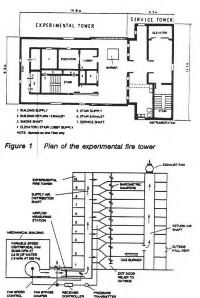
Figura I Plan of the experimental fire tower
Figure 2 Experimental tire tower with test equipment
experimental fire tower were described in Tamura (1989).
The floor plan showing the location of the test stainhaft is reproduced in Figure 1. The leakage areas of the tower were set to simulste those ot a building wlh average airtightness
and a floor area
of
9730 f? (904fi,
or
seven times that ofthe floor area of the experimental fire tower. The values of
leakage areas for the tower given in Table 1 were arrived at from measurements of other buildings conducted by Tamura and Shaw (1976, 1978).
The experimental fire tower was equipped with various overDressure relief features, as shown in Figure 2. The
--
George T. Tamura is Senior Research Officer, Institute for Research in Construction, National Research Council of Canada, Ottawa.
THIS PREPRlNT IS FOR DISCUSSION PURPOSES ONLY. FOR INCLUS~ON IN ASHRAE TRANSACTIONS 1990, V. 96. Pt. 2. Not to be reprinted in whole Or Part
without wrlnen perrnlsslon ot the Amer~can Society of Heating, Refrigerating and Airconditioning Engineers. Inc.. 1791 Tullie Circle. NE. Atlanta. GA 30329. O~lnlons. flndlngs, conclus~ons, or recommendations expressed In this paper are those ot the author(s) and do not necessarily reflect the V I M Of ASHWE.
supply air shaft Is adlaeerrt to the s t a i m with eir outla openings to permit Injection al suppty air on any l b r . The
supply air duct system is connected to a cemrlfqal h n in the adjacent mechanical building. The
tan
has a capacity of 38,000 cfmat
2.6 In. of water (18 m3/s at 650 Pa) and avar~ablaspeed drrve. The adlow rneasurlng stallon is located
In the duChvork Mnnected to the
bottom
d the atr distribution shaft. R consists of mulll-point setf-awagtng totalpressure tubes and their associated static pressure t a p (Ma t96q and an atr strargMener
d
honeycomb panel located immedrately upstream d the averaging tubes. Two propane gas burner sets, each capable of prmuang heal alan
output of 8.5 m~llion 0 t d h (2.5 MW), are locafed on thesecond ff00r. Outside wall vents In the east and west walls of the second floor, each with an area of 5
+
( 0 . W m?, can be opened remotely during a flre test to simulate broken windows.For the stair pressuruation system with exit door relief, the stair door and the exit door on the first floor can be
opened to provide pressure relief to the outdoors. For the stairshaft pressurization system with barometric damper relief, a barometric damper 3 ft by 3 ft (0.91 m by 0.91 m) with three horizontal blades and an adjustable counterweight was installed in the stairshaft wall at each floor on the corr~dor s ~ d e to prov~de pressure relief to the adjacent floor space.
For the stairshaft pressurization system with feedback control, a static pressure transmitter was located on the ffih floor of the service tower with the transmitter connected with plasfic tubings to the pressure taps inside the stairshdt and the floor space of the same floor of the exprlmerrtal fire tower. The receiver controller was located in the control room of the single-story service building adjacent to the tower. By means of a four-position switch, the contrdkr can
be set to control either the two motorized dampers of the
fan bypaw or the variable-speed drive of the centrifugal fan to maintain the pressure difference a c r m the stair door on
the f i h floor at the setpoint by varying the supply alr rare to
the stairshaft.
TEST PROCEDURE
For all tests, the dwropenlng sequence was
essentWly
the same as the one used during thePhase
2 field tests, with the second noor designated as the fire floor and stair doors on the exfl floor, fire floor, one a b w e the fire floor, and oneof
the upper floors opened sequentially. For all pressurization systems, the supply air was injected Inslde the stalrshaft on floors 1, 3, 5, 7, and 10. The stairshaftpressurization systems were tested under the following schedula:
Nonfire Tests with Stairshaft Pressurization:
1. No doors open
2. Stair doors open on Floors 1 and 2
3. Stair doors open on Floors 1, 2, and 3
4. Stair doors open
on
Floors 1, 2, 3, and 8Measurements were conducted with the above dooropening schedule, first with the exterior wall vents
on
the second floor closed and then with them open.Fire Tests with Stairshaft Pressurization:
. -
1. At a fire temperature of 840r ( 4 v and wRh the
ewterlor wall vents on the second flow closed (Intended as a low-temperature fire), the above door-opening sequence
was
forowed until a
backfFow a? the slab door opening onthe second floor was observed. The stair door opening on the fire floor was decreased until backflaw was prevented
w
TABLE 1
b a k a g e Flow Amaa per Floor
of the Experimental Fine Tower ).
M o n Ama
Outd* mils ft2 ma
1 st floor east wall 0.59 0.055
1st floor floor west wall 0.59 0.055
2nd floor east wall (wall vent closed) 0.59 0.055
2nd floor east wall (wall vent open) 5.00 0.464
2nd floor west wall (wall vent closed) 0.59 0.055 2nd floor west wall (wall vent closed) 5.00 0.464
Typical floor east wall 0.39 0.037
Typical floor west wall 0.39 0.037
Elevator
Floor space to elevator shaft 0.07 0.006
Floor space to elevator lobby 0.30 0.028
(lobby door closed)
Floor space to elevator lobby 21.00 1.951
(lobby door open)
Elevator lobby to elevator shaft 0.75 0.070
(elevator doors closed)
Elevator lobby to elevator shaft 6.00 0.557
(elevator doors open)
Stain
-
Floor space to stairshaft 0.04 0.004
Floor space to stair lobby 0.25 0.023
(lobby door closed)
Floor space to stair lobby 21.00 1.951
(lobby door open)
Stair lobby to stairshaft 0.25 0.023
(stair door closed)
Stair lobby to stairshaft 21.00 1.951
(stair door open)
Vertical Shafts
Floor soace to service shaft
Floor space to supply air shaft' 2.00 0.186
Floor space to return air shaft' 2.00 0.186
Celling 0.56 0.052
'Supply and return air openings sealed on the 2nd floor
and the
door
angle at the point of no backflow was noted. Exterior wall vents on the second floor were opened forsome ol the low-temperature fire tests to determine their
effect on air velocities at the stair door opening on the same
floor.
2 At fire temperature
at
1MOT (650%) and with theexterior wall vents open (intended as a high-temperature fire), the
above
door-opening sequence was follovved untrla backflow at the stair docx opening on the second flwr was observed. The stair door was again gradually closed and the door angle at the point of na tMcMlow was noted.
Pressure differences across stair doors were measured with a d i i r a g m - t y p e magnetic reluctance pressure transducer and the supply air rates for stairshaft
pressudzation
were measured at the flow-measuring station.Temperatures were measured with chromel-alumel
thermocouples. The average air veloclies at the stair door
opening
on
the second
floor during nonfire tests were measured by canying out a 21-point hot-wire anemometer traverse. They were averaged to obtain the average air velocity. Smoke backitow during the fire tests was determined with smoke sticks at the stair door opening on the second floor. Carbon dioxlde concentrations in the tower were measured with nondispersive infrared gas anatyters.The stair pressurization systems were tested under both
summer and winter conditions. Pressure measurements were conducted in wifitter without stairshaft pressurization to determine the influence of stack action on pressure
PRESSURE DIFFERENCE ACROSS STAlR WORS. Pa
A 0.
STAR OOORS OPO(
7
:I I
OHW)(CAEDRoORsI
b)- JOF(4.c)
8
7 ON IH)ICATED FLOORS STAIR COCRS OPEN
WRY AH RATE
1 7,800 an w.4 mlk)
I
PRESSURE DIFFERENCE ACROSS STAIR DOORS. INCH OF WATER
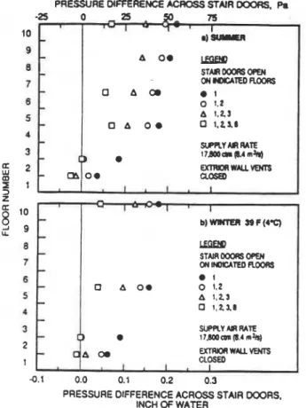
Ngure 3 Pressure difference measurements of stair pressurization system with exit door relief, nonfire conditions
differences across the stair doors and on airflow velocities
at the stair door opening on the second floor. They were conducted with either the exterior wall vents on the second
floor or the stair door
on
the first floor open and also with a combination of both.Tests were conducted to check the feedback control system of the stairshaft pressurization systems with fan bypass and the variable-speed drive fan. The response time of both pressurization systems to changes in stairshaft pressures caused by opening and closing of stair doors were obtained by recording, on chart recorders, the pressure differences across the second floor stair door and the rate of supply air for pressurization.
For the feedback control systems, tests were also conducted to find a suitable location for the reference pressure side of the static pressure transmitter to prevent overpressurization of the stairshaft. With the reference pressure tap located on the fifth floor, either in the floor
space or inside the service shaft, pressure differences
. across the stair door on the second floor were measured with the stair door on the fifth floor closed and then open. Also, to check the suitability of the rooftop as the reference pressure, pressure differences between the stairshaft and the adjacent floor space and that between the stalrshaft and rooftop were read on the chart recorder under varlous wind conditions.
RESULTS AND DISCUSSION Stair Pressurlzatlon System with Exit Door Relief
Nonfire Conditlons Pressure differences across the stair doors for summer in the nonfire condition are shown in Figure 3a Tbe supply air rate for pressurization was 17,800
cfm (8.40 m3/s) to produce a pressure difference
across
the stair door on the second floor of 0.10 in. of water (25 Pa) with all stair doors closed except for the oneon
the first floor leading to the outdoors. The pressure dierences were the smallest, 0.036 in. of water (10 Pa), on the first floor across the stair door leading to thefloor
space, and they were largest (0.218 in. of water [54 Pa]) on the tenth floor. This pressure pattern was caused by the flow resistance ofthe stairway with pressure drops occurring downward in the direction of flow toward the open exit door. The pressure differences decreased as the stair doors
on
floors 2, 3, and 8 were opened in succession. Except for floors 1 and 2, all the pressure differences were above 0.10 in. of water (25 Pa) when the doors on floors 1, 2, and 3 were opened, and they were above 0.05 in. of water (12.5 Pa) when the door on floor 8 was also opened. The pressure differences on floor 2 were near zero, and those on floor 1 were above and below zero in all cases. Pressure differences measured during winter with an outside temperature of 39°F (4°C) are shown in Figure 3b. The pressure pattern in winter is similar to that of summer. Compared with the summer readings, the pressure differences were lower above the second floor, but they were higher on the first and second floors.Table 2a gives the pressure difference and the average air velocities at the open stair door on the second floor measured during the door-opening tests with the exterior wall vents on the second floor closed and open. The measurements were conducted with no fire under both summer and winter conditions. Wihout exception, both the average air velocities and pressure differences were greater with the exterior wall vents open than with them closed, and they were greater for winter than for summer conditions. Wih the exterior wall vents closed, the pressure differences were near zero, whereas with them open, the pressure differences varied from 0.008 to 0.016 in. of water (2 to 4 Pa). For the summer conditions, the average air velocities varied from 33 to 118 fprn (0.17 to 0.60 m/s) with the exterior wall vents closed as compared to 197 to 285 fprn (1 .W to 1.45 m/s) with them open. For the winter conditions, the average air velocities varied from 59 to 143 fprn (0.30 to 0.73 m/s) with the exterior wall vents closed as compared to 236 to 320 fprn (1.2 to 1.63 m/s) with them open.
Fire Conditions Table 2b gives the observations of
smoke backflow into the stairshaft at the open stair door on the second floor during the fire tests. For both the winter
and summer condiiins with a fire temperature
of 8504 (454OC), smoke backflow occurred when the aair doors on the first and second floors were open and the exterior wall vents were closed. Smoke backflow, however, was prwented when the exterior wall vents were open. The average air velocity for the nonfire conditions corresponding to the latter case was 285 fprn (1.45 m/s). When the stairdoor
on the third floor was also opened, smoke backflow occurred for the summer and winter conditions with a greater amount d backflow for the summer conditions. With a fire temperature of 12005 (650°C). the first and second floor stair doors open, and the exterior wall vents open, smoke backflw occurred for the summer conditions butnot
for the winter condiions. For the latter conditions, the average air velocity was 320 fprn (1.63 m/s) for the corresponding nonfire conditions. Under the winterconditions when the stair door on the third floor was also opened, smoke backflow occurred.
Smoke backflow can be prwented by partially closing the door on the second floor. The required door angles to accomplish this are also given in Table 2b for the varlous test conditions. For example, when stair doors on the first
and second floors are open and the exterior wall vents closed, smoke backflow can be prevented with a door angle on the second floor of 10" in summer and 1 7 O in winter.
-
.I
Pressure dMerences measured under nonfire conditions PRESSURE DIFFERENCE -A STNR WOIIS. P.
indicated that the werage air velocities at the second floor -50 0 50 100 150
stair door were considerably higher when the exledor wall
vents were
m
than when t 9d the vent o Ings was 10 wlth a stair d m
I opening d ?02 (1.86 m2), from series flar considerfibns,
a larger vent
sirs
would- have resutledIn
greater air 7 velmrties. tl would, therefore, be expected that mechanical 8ventlng of the fire flm would also resuh in air velwaies 5 greater than those with exterior wall vents closed.
Because
of
stack action with the exit door open to the 43
outdoors, the stalr pressurization system pefformed better
under winter than under summer conditions.
5
2 - mStair
Pressurization System
z4
-
-
-
-
-
-
-
CI-
wlth Barometric Damper Relief 1
-
' 1b ) m PC(dW With all stair doors closed, the counterweights of the
- .
m QOSED I , I , I t o - ' 1,)- 0 m
LEma
S T M 1 ~ O P E N CN -TED ~ 0 0 ~ 9 W O E 0 m 8 0 1 0 1.2 . A 1.23 OdD 8 0 1.23,. S I P R Y MAATE.
a ? C o o o o l ( 1 3 2 m ~ Q a r m R w A L L m 8 barometric dampers were set to give a pressure differenceacross the stalr doors of 0.40 in. of water (100 Pa), which 7 is the maximum allowable pressure difference across the a stair door to avoid door-opening problems. The blade
5
angles of the barometric dampers were about 35' open and
th
8
corresponding supply air rate was 28,000 cfm (13.2 Jm IS), a much greater rate than for the stairshaft 3
pressur' ation system with exit door relief
'5
of 17,800 cfm 21
(8.40 m Is).
-
m o1
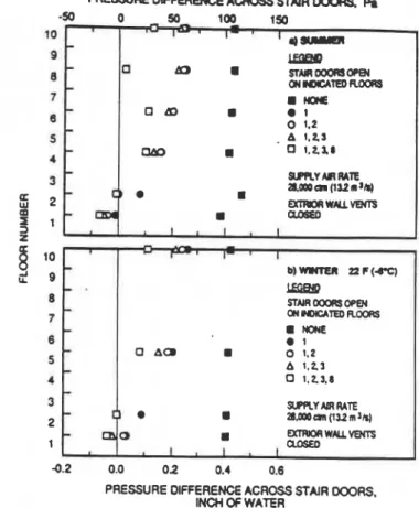
Nonflre Condltlons Pressure differences across the
stair doors for summer in nonfire conditions are shown in 0.2 0.0 0 2 0.4 0.6
Figure 4a With all
@air
doors closed, the pressure PRESSURE DIFFERENCE ACROSS STAIR WAS,dkfferems were just ahwe 0.40 in. of water (100 Pa). With INCH OF WATER
all doors
closed
except for the one on the Rrst floor readlng Figure 4 Pressure difference meesunments d steirto the M d m , the pressure difference was least on the pressurkation system with barometric damper
first Rmr a c r m the stair door leading to the floor space, relief, nonfire conditions TABLE 2
Pressure Dlffemnce, Avenge Air Mloclty, and Smoke Backflow Measummenta at Stair Door Opening
on
the Fire f l o o r (Secondfloor)
of Staimhaft ~ r l t a l o n System wlth Exit Door RellefS P P b Proswn AwqeAlr Door Angle
OW Air d ate ~ h m n c e ~dodty supply nn smob to stop
Doors, 8cfm Wide In. of fpm
w
Air- Outside Temp. Backflow, Smokenoor (m3/r) W l h n t s -(Pa) (I&) Doon, sctm Wall OF % oiOoor W l o w
Floor (m3h) Venta (*C) Area Degree
20 Nonfln Condbn
2b Fln Condition Summer Condition-4OF (20°C), 6 mph (10 kmh) southeast
1,2 17.800 dosed 0.005 118 Sumnm CoclditIon-68OF (a%), 6 mph (10 kmh) southeast
(8.40) (1.2) (0.60) 1,2 17,800 closed 824 35 10 open 0.016 285 (8.40) (440) (4.0) (1.45) 1,2,3 closed 0.000 57 open 840 0
-
(0.0) (0.29) (485) Open 0.010 244 1,2.3 942 25 28 (2.5) (1.24) (506) 1,2,3,8 closed 0.000 33 I (0.0) (0.17) 1 2 1175 20 43 open 0.008 197 (635) (2.0) (1.oo)
1 2 3 30 23Winter Cocrditlo11--39~F (4'C), 13 mph (21 kmh) west
1,2 17,800 dosed 0.005 1 43 winter (40C1, 13 mph (21 kmh) west
(0.40) (1 4 ( O m 1,2 17,800 dosed 850 35 17 o w n 0.016 320 (8.40) (45s) (4.0) (1.63) open 0
-
1.2,3 closed 0.000 83 (0.0) (0.42) 1,2.3 1 90 open 0.010 268 (2.5) (1 36) 1,2.3,8 10 37 1.2.3,8 closed 0.000 59 1,2 (0.0) (0.30) 1200 0 open 0 010 236 (650) (2.5) (1 20) 1,2.3 10 67-
-
-
-
-
-
UEw STM OOORO OPEN CN~TODROORS 8 rONE 1 a AC. a 0 1.2 A 1.23 0 1.21.8 SUPRYAERRATE t . 8 I.LWan(112mJNwith a value ol 4.012 In. of water (3 Pa), and was highest
on
the tenth floor at 0.25 In. d water (62 Pa). This pressure a pattern is similar to that of the stairshaft pressuriiation system with exit door relief. The pressure differences decreased as the Stair doorson
floors 2, 3, and 8 were opened in succession. Exceptfor
floors 1 and 2 the pressure differences across all closed doors were above 0.10 in. of water (25 Pa) whendoors
on
floon 1, 2, 3, and8 were opened. The pressure difference on floor 2 was 0.08 in. of water (20 Pa) when only the stair door
on
floor 1 was open, and it was near zero when addiional doors were opened. Pressure differenceson
floor 1 were negative except for the case with all doors closed. Pressure differences measured during winter with an outdoor temperature of 225(4%)
are shown In Figure 4b. Thepressure pattern in winter is much the same as in summer, except that the pressure differences
on
the first and second.. floors are somewhat higher In winter than in summer. This was also the case with the stair pressurization system with exit door relief. The Influence of stack action
on
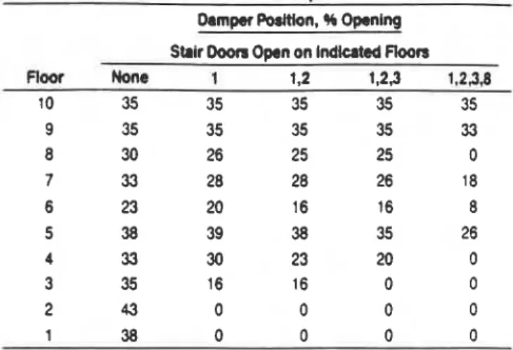
these pressure differences is discussed later.Damper positions during the door-opening tests are given in Table 3. On floors where the stair doors were opened, the dampers closed completely with no further influence on the stairshaft pressures; on other floors, they remained in their initial position or were closed by a varying amount.
Table 4a gives the pressure differences and the average air velocities at the open stair door
on
the second floor during the dooropening test with the exterior wall ventson
the second floor closed and open. The measurements were conducted with no fire under both summer and winter conditions. Both the average air velocities and pressure differences were greater with the exterior wail vents openTABLE 3
Damper Positions of Staimhatt Pressurization Systems with Barometric Damper Rellef
Dam* Podtlon. % O m l n g Strlr Ooon O p n on lndkated Ftoors
n-
one
I 1.2 1.23 1.2361 38 0 0 0 0
than with them closed, and they were greater for the winter than for the summer conditions. With the exterior wall vents closed, the pressure differences were near zero, whereas with them open, the pressure differences were about 0.01 1 in. of water (3 Pa) in summer and 0.013 to 0.018 in. of water (3 to 4 Pa) in winter. For summer conditions, the average air velocities varied from 43 to 106 fpm (0.22 to 0.54 mls) with the exterior wall vents closed, as compared to 246 to 309 fpm (1.25 to 1.57 m/s) with them open. For winter conditions, the average air velocities varied from 48 to 158 fpm (0.25 to 0.81 mls) with the exterior wall vents closed, as compared to 280 to 380 fpm (1.43 to 1.93 m/s) with them open.
Flre Conditions Table 4b gives the resuls of the fire tests. For both the winter and summer conditions with a fire TABLE 4
Pressure Difference, Average Air Velocity, and Smoke Backflow Measurements at Stalr Door Opening on the Rre Floor (Second floor) of Stalrshaft Pmssudzatlon System with Barometric Damper Rellef
SuPPb Pmuure Average Air Door A g k
O P n Air Rate l M h n c e
m
s u m Flre Smob tostopDoon, scfm Outside In. of fPm
o w
Alr Rate' Outside Temp. Backflow, SmokeFloor (m3h) MIIIlbn8 W(Itu(R) (mh) Doom, scfm Wall O F %of Door W o w
Roor (m31s) Venta ("C) A m Dbgm C Nonfin Condbn
4b Fire CondiUon Summer Conditio11-82~F (28%). 6 mph (10 kmh) northwest
f , 2 28.000 closed 0.000 106 sum^ Condiion--68°F (20°C), 6 mph (10 kmh) southeast
(13.2) (0.0) (0.54) 1.2 28.000 closed 932 35 10 open 0.01 1 309 (1 3.2) (500) (2.7) (1 57) 1.2 open 833 0
-
1 2 3 closed -0.004 53 (-1.0) (0.27) (445) open 0.01 1 (2.7) 1.2.3.8 closed-
0.007 (-1.7) open 0.01 1 (0.0) Winter Condition--
Z ° F ( -6OC). 9 mph (15 kmh) southwest1 2 28,000 closed 0.001 (13.2) (0.2) open 0.01 8 (4.5) closed 0.001 97 (0.2) (0.49)
Wlnter Condltlon--
-
Z ° F , ( -6OC), 9 mph (15 kmh) southwest1,2 28,000 closed 840 40 13 (8.40) (450) 1,2.3,8 closed -0.003 48 1.2.3 1200 0
-
(-
0.7) (0.25) (650) open 0.013 281 (3.2) (1.43) 1.2.3.8 10-
temperature d 85(K (454%). smoke baddkw occurred
when the stair doors were
o p n
on
the flrsl and second floors and the exterior w d ventsclosed
whereas smoke backflow was prevented with the exterloc wall ventsopen.
Under summer conditions with the exterior watl vents open, smoke backflw was also prevented when the stair dooron
the third floor was opened. The everage air velocity was 270 fpm (1.37 mls) for the corresponding nonfire conditions. Smoke backflow occurred, however, when the stair door
on
the eighth floor was opened too. Also under summer conditions, at a fire temperature of 1MO"F (650%) smoke backflow occurred when the doors on M r s 1, 2, and 3
were open. Under the winter condition with the exterlor wall
vents open, smoke backflw was prwented when doors
on
floors 1, 2, 3, and 8 were open at fire temperatures d 8405
(450%) and 12005 (650%). For the latter fire temperature, the average air veloctly was 281 fpm (1.43 mls) for the corresponding nonfire conditions.
The stair pressurization system with bamrwtric damper
relief performed better than the sygtem with exit door relief In t e r n d the number
of
doors open without smokebacMfow et the sfalr door opening
on
the second flow.However, the supply air rate for pressurltailon of the stab pressurization system with barometric damper relief was about one-and-a-hatf times that of the stair pressurization system with exit door relief.
Stalr Prerrsurlzatlon System wlth Fan Bypass
a
Nonnra Conclttlons Pressure dierences a u a
the
W r
doors
for tha summer and nonflre conditionsare
shOwnin Figure 5 a With all doom clewed, the pressure differences 4 *rere Just .Dw 0.10 in, of water (2s Pa). Jhe suppty air rate
tor
pressurization was 1700 (0.81 m is).me
pressure(
differences above the third floor remained at this pressuredifference when the stair d m n on floors 1, 2, 3, and 8 were
opened In succession. The supply air rates increased to
13,300; 44,300; 17,200; and 30,000 cfm (6.26, 6.75, 8.13, 14.14 m Is), respectively, with Ihe above sequence of stair
dux opening. When the stair doors were open
on
flm 1.2,
and
3, the supply air catas were about equal to that of the pressurization system with exlt door relief. When the stairdoor
on
the eighth floor was opened as well, the supply air rate was more than that of the pressurization system with barometric damper relief. Pressure differences on floon 1and 2, however, fell well below the setpoint value when the
stair doom were opened,
as
shown In Figure 5aA separate test was conducted with all stair doors closed except for the one on the fifth floor, where the pressure transmitter for the controller is located. Although the pressure difference across the stair door on the ffih floor was controlled at 0.10 in. of water (25 Pa), those on other floors increased to about 0.60 in. of water (149 Pa), which can make door opening difficutt.
Pressure differences measured during winter with an
outdoor temperature of 215 (-6%) are shown in Figure 5b. The pressure pattern in winter is similar to that of summer. The setpoint of the receiver controller of the feedback except that the pressure differences
of
the first and second control wasset
nominally at 0.10 in. of water (25 Pa) across floors are higher thanthose
in summer, as for the two the stair door on the fnth floor. The pressure transmmer was previous pressurization systems.located on the fifth floor, connected by plastic tubings
on
Table Sa gives the pressure differences and the average the one side to the stairshaft andon
the other side to the air veloc'iies at the open stair door on the second floor floor space of the same floor. during the doorapening test with the exterior wall vents onTABLE 5
Pressure Dlffemnce, Average Alr Velocity, and Smoke Backflow Measurements at Stair Door Opnlng
on the Flm Floor (Second floor) of Strlnhaft P~brwrlzlltlon System wlth Fan BY?-
C
SUP* pmnUm -Ah Door Angk
Alr Rate Dlfbmlm
m
s u m F h sntol(e to StopDoofS, ttlm O w d o in. of fpm
w
Air- 0- Temp. Blckndw, Smokefloor (m3h) WIWnts Waterpa) (mh) Doon. schn W d l OF notooor MW
Floor (m31r) Vents ('C) A m Dagm SI Nonflm Conditan
- - . - . . . - - - . . -. - - . .
Summer Condition--68F (20%). 6 m ~ h . ,- (10 kmhl southeast
1,2 14.300
clos;ed'
0.005 130 S u m m C0nditiin--K3~F (1 7OC). 5 mph (8 kmh) northwest(6.75) (1.2) (0.66) 1 2 13,250 closed 840 40 10 15,250 o m 0.012 290 (6.26) (450) (7.20) (3.0) (1.48) 1 2 15.250 open 880 5 56 1 ,2,3 17,200 closed 0.002 87 (8.1 3) (0.5) (0.44) (7.2) (470) 17.700 open 0.01 1 254 (8.37) (2.7) (1.29) 1,2,3,8 30,000 closed 0.000 55 (14.14) (0.0) (0.28) . II 31,100 open 0.012 275 (14.69) (3.0) (1
.a1
Winter CondHion-
-
21 "F ( - 6OC), 12 rnph (20 kmh) southwest1.2 13,100 closed 0.005 142 (6.1 8) (1.2) (0.73) 15,406 Open 0.020 327 (7.28) (5.0) (1 . a ) 12.3 16,950 closed 0.003 94 (8.00) (0.7) ('3.48)
Wlntr Conditiorr- -21 OF. (-6OC). 12 mph (20 kmh) southwest
1.2 13,100 closed 840 40 14 (6.18) (450) 19,150 Open 0.018 306 18,600 1.23 0
-
(9.03) (4.5) (1.55) 1 ,2,3,8 31,200 closed 0.001 74 1.2.3.8 30.800 0-
(14.73) (0.2) (0.38)PRESSURE WFERENCE ACROSS STAIR DOOAS. Pa -25 * 8 STAlR OOORS 7 M(CATE0 AHIWE I ' I -0.1 0.0 0.1 0.6 0.7
PRESSURE OlFFERENCE ACROSS STAIR DOORS INCH OF WATER
Figure 5 Pressure difference measurements of stair pressurization system with fan bypass (reference pressure for the controller on the 5th floor), nonfire conditions
the second floor closed and open. The measurements were conducted with no fire under both summer and winter conditions. Both the average air velocities and pressure
dflerences were greater with the exterior wall vents open than with them closed, and they were greater for winter than
for summer. With the exterior wdl vents closed, the pressure differenm were near zero for both summer and winter,
whereas with them open, the pressure difterences were about 0.012 In. of water (3 Pa) In summer and about 0.01 9
in. of water (5 Pa) in winter. For summer conditions, the average air velocities varied from 55 to 130 fpm (0.28 to 0.66 Ws) whh the exterior wall vents closed as compared to
275 to 290 fpm (1.40 to 1.48 m/s) with them open. For winter conditions, the average air velwities varied
from
74 to 142 fpm (0.38 to 0.73 mfs) with the exterior wall vents closed as compared to 327 to 339 fpm (1.66 to 1.70 m/s)with them open.
Fire Tests Table 5b gives the results
of
the fire tests. For summer conditions with a fire temperature of 850S(454%), smoke backflow occurred when the stair doors
were open on the first and second floors
and the exterior
wall vents were closed; smoke backflow also occurred with them open but was considerably less than with them closed. For winter conditions, smoke backflowalso
occurred when the stair doors on the first and second floors were operr and with the exterior wall vents closed. With the exterior wall vemsopen,
hmever, there wasno
m e backPlow withstalr doors open on Roan 1,2,3, and 8 1 fin temperaturea
of MOT (450°C) and 12WF (6%). for the #mesponding
nordire case, the average d r velocity was 339 fpm (1.70
mls).
The minimum average air velocity ty Vleitlomtested was 306 fpm (1.55 mls) with stair doors open on floors 1, 2, and 3 a! a fire temperature
o
f
S W F
(450°C).With this
system
under conditions of summer and a low-temperature fire, smoke backflow occurred with the stair doors open on the first and second floors and the exteriorWall vents open, whereas it did not occur with the stalr pressurization system with exit door relief or with barometrlc damper relief. This was probabty due to the supply air rate
of tfie fan bypass System being lwer than those of the two other systems for this test condilorr.
Examination of
Feedback
Contrd Sy8tem With thereference pressure tap of the static pressure transmitter located on the floor space of the fifth floor, the stairshaft was highly werpressurized when the door on that floor was opened (Figure 5a). To avoid this, the reference pressure tap of the static pressure transmitter was moved from the floor space to inside the service shaft
on
the same floor. With the stairshaft pressurized, the stair door was opened on the fifth floor; the pressure difference across the stair door on the second floor was 0.1 14 in. of water (28 Pa). It was considerably less than the pressure difference across the stair door on the second floor of 0.640 in. of water (160 Pa) (see Figure 5a) obtained with the reference pressure In the floor space of the fifth floor and with the stair door on thisfloor
open.To investigate the suitability of the rooftop as a reference pressure, pressure differences between the stairshaft and floor space and that between the stairshaft and rooftop in a sheltered area were recorded on a chart recorder for wind speeds of 2.5 mph (4 krnh), 13 mph (21
kmh), and 18 mph (30 kmh); the stairshaft was not pressurized. The pressure differences between the stairshaft
and floor space remained steady at zero readings for the two lower wind speeds; that for the highest wind speed was
-0.01 20.002 in. of water (-2.5 20.5 Pa). The pressure differences between the stairshaft and rooftop, however, were 4.017 in. of water (4 Pa) with small fluctuations for a wind speed of 2.5 krnh (4 krnh), -0.040 20.060 in. of water
(-10 215 Pa) for a wind speed of 13 mph (21 krnh), and
-
0.06 k0.10 in. of water (15 225 Pa) for a wind speed of 18mph (30 krnh). These readings indicate that with the reference pressure tap at the rooftop, the static pressure controller can be affected by wind pressures. These tests indicated that the most suitable location for the reference pressure tap was inside the service shaft.
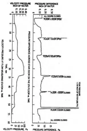
Figure 6 Response time of stair pressurization system with feedback control-fan bypass
The performance of the feedback contmlk Is illuamed in Figure 6. The pressure diiererlm across the stak door
on
the fiih floor and the velocity pressure of the
aMow-
measuring station with respect to time are shown when the star doors were opened quentlally. Initialty. the pressure d i m n c e was 0.133 in. of water (33 Pa). When the
stair
ctoor
on the s m d floor was opened, the pressure differme decreased sharpty and then Incre8sed gradualtyto retom to
na
Initial reading. ll took 70.5 minutes to reach its hrtfal reading and 5 minulm to reach 75% d ds orlgind reading; when the sldr doon on theflm
and then the eighth fioor were opened, the response times were 6minutes
and
1.2 minutes, and 8.5 minutes and 4 minutes, respectively. When the stair doors were closed In the reverse order, the pressure difference increased momentarilyand then
decreased
to its 0rigiMI reading. The times to reach this reading were 5 minutes, 4.5 minutes, and 5.5minutes when the stair doors
on
the eighth, first, and second floors were closed in turn. When the last door was closed. the pressure difference increased to a peak at 1.470in, of water (365 Pa) wflh a loud laboring sound from the fan and dropped to 0.30 in. of water (75 Pa) in 50 s. Because
of the lag of the feedback control system, smoke
contamlnat~on of the stairshaft
can
occur rnomentwlty due to a loss of pressurlration when stair doors are opened.Stalr Pressurization System
with Variable-Speed Fan
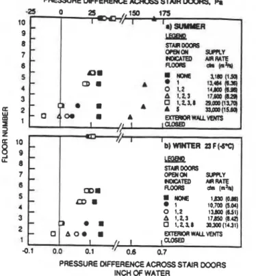
PRESSURE MFFERENCE ACROSS STAIR OOORS
INCH OF WATER
Figure 7 Pressure difference measurements d stair
The results
d
themeasurements
for this system, whkh pressurizatfon system with variabie-speed fanare
given h Figures 7a and 7b and Tables 6a end 6 4 were (reference pressure for the contrdI81 on the 5th similar to those ol the stair pressurlzatim gmem whh fan floor), &re conditionsbypass. The excaption was that smoke bacMtow occurred
for
the high-temperature case under winter conditiwrs whenTABLE 6
Prewure Difference, Awmge Air Wloclty, and Smoke Backflow Measurements at Stair Ooor Opening on the
Fire
Floor (Second Floor) of Stdmhatt PrsrurriutionSystem
with Varlable-Speed Fans
u
m
Air Rate
-
Awrrrgrm Doof Angko w
-
-
supplr Fin Smdo tostopDoon, rctm OuWda in. af fpm 0P.n Air- Outr#r Temp. BuMbw, Smoke
floor (m3h) Wall Vmtr
-(PI)
(mh) Doon, acfm WdI *F SCotDoor h c l d k wnoOr (m31s) Vmta ('C) Area Dogma 8r N d n Condbn Summer Condition--650F (18%), 2 mph (4 kmh) 1,2 14,800 closed 0.004 (7.00) (1.0) 16,000 O W 0.015 (7.54) (3.7) f,2,3 17.560 closed 0.004 (8.29) (1 .O) ,I 18.500 open 0.010 (8.74) (2.5) 1,2,3,8 29.000 closed 0.000 (13.7) (0.0) 30,150 O m 0.016
Summef Codtlon-6S0F (1e0C), 2 mph (4 kmh)
1.2 14,800 dased 860 40 10
(7.00) (460)
(14.2) (4.0) (1 31)
Winter Condition- -23OF. (-S°C), 12 mph (20 kmh) southwest
Winter Condltlon--
-
23OF ( -S°C), 12 rnph (20 kmh) southm#1 1.2 12.540 dosed 850 40 131.2 13,800 cbsed 0.006 1 36 (6.51) (1
.a)
(0.69) (5.92) (454) 1,2.3 17,850 closed 0.005 102 (8.42) (1.2) (0.52) 1,2.3 23.300 * 850 0-
18,700 Open 0.018 367 (7.54) (454) (8.82) (4.5) (1.w
1,2.3,8 31,700 0-
1,2.3,8 30.300 closed 0.002 80 (15.0) (14.31) (6.5) (1.89) 31,700 open 0.018 372 12.3 19.200 1200 20 38 (14.35) (6.5) (1.89) (9.08) (650)P O O P P P
a +
s - g I adm- s
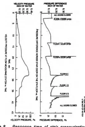
Figure 8 Response time of stair pressurization system with feedback control-variablespeed fan stalr doom on floors 1, 2, and 3 were open, whereas for the fan bypass system, smoke backflow was prevented when stair doors were opan on floors 1, 2, 3, and 8.
Examlnatlon uf Feedback Control System The
periorrnance of the pressure comrd sysfern tested under the
same condition as the bypass system is illustrated in Figure 8. When the stair doors on floors 2, 1, and 8 were opened
in succession,
R
took 9 minutes, 5 minutes, and 7.6 minutes to reach its i n R i reading and 5 minutes, 1 minute, and 3.2mlnutes to reach 0.10 in.
of
water (25 Pa)or
75% of its original reading. When the stair doors were closed in thereverse
order, the pressure ditterence increased rnomentarityand then decreased to its original reading. It took 5 minutes,
2.7 minutes, and 5 rnhutes to reach these readings when the stair doors on the eighth, first, and second floors were closed in turn. When the last door was closed, the pressure
difference
peaked at 0.728 in. of water (I80 Pa) and dropped to 0.30 in.of
water (75 Pa) in 50 seconds. These response times are slightly less than those fos the pressure ComrOl system of the stair pressurization system with fanbypass.
Pressure Differences across Stair Doors Caused by Stack Action
Comparison
c4
the pressure differences across !he stairdoors measured during winter and summer tests indicated ; that whm the stair door on the fim floor was opened
lo
the outdoors, the pressure differences at the lower flmrs weremore favorable
in winter than in summer. Consequentty, in winter during the doorspening tests, the average air velocitlesat
thedoor
opening on the second floor weretugher and the stair pressurtzatbn system pedormed bmer In prwenting smoke backlow than in summer.
The results
of
prwure measurements conducteda
an
outdoor tempemure Of 304 (-1°C) and wlthout s H r s M
pressurization are shown ~n Figure 9. The wind speed was 12 rnph (19 krnh), which may have distorted m e w h a t the
pressure drfferences caused by Stack action. With all stair
doors closed, the
neutral
presure level of the stairshM islocated at about the mid-height of the tawer. The pressure
PRESSURE DIFFERENCE ACROSS STAIR 000A. Pa
-25 0 25
$a
r-
I1
PRESSURE DIFFERENCE ACROSS STAIR 000RS. INCH O f WATER
Figure 9 Pressure differences across stai? doors caused
by stack action
differences across the stair doors on the first and second floors are -0.008 in. of water (-2 Pa) and -0.023 in. of water (-6 Pa), respectively, with air flowing from the floor spaces to the stairshaft. When the stair door
on
the first floor leading to the outdoors was opened, the direction of airflow reversed, with pressure differences of 0.022 in. of water (5Pa) for the first floor and 0.013 in. of water (3 Pa) for the second floor. When the stair
door
on the first floor was closed and the outside wall vents on the second floor were opened, the pressure diierences across the first and second floor doors were -0.010 in. of water (3 Pa) and -0.030 in. of water (-7 Pa), respectively. When both the stair dooron
the first floor and the outside wall vents on the second floor were opened, the pressure differences across the first and second floors were 0.022 in. of water (5 Pa) and 0.005 in.of water (1 Pa).
These measurements indicate that
stack
action under winter conditions can assist stair pressurization systems when the stair dooron
the first floorIs
6&ned to the outdoors. On the other hand, opening the exterior wall vents on one of the l w e r floors, simulating broken windows, can have a negative effect. Hwever, when the stainhaf! is pressurized, the average air velocities at the stair door opening with the exterior wall vents open are considerably greater than those obtained with the exterior wall vents closed because the buildup of pressures in the floor space with the wall vents closed is relieved when they are opened. Air velocities at the vertical centerline of the open stair door on the second floor with the stairshaft pressuriuationoff
are given in Table 7. When the stair door on the first floorTABLE 7
Air Velocities at Open Stair Door on the Second Floor Caused by Stack Action
outside T m p e m t u ~ 3 0 . F (-1%) Wind-12 rnph (19 kmh) south
W M Cmtdi~ Alr Wity at Open Sbir Door on Sscond Floor, tpm (mls)
was opened, the
air
v e k h i e j hto seecnd b x variedfrom 112 Vpm (0.57 rrlls) near the
m
o
m
to 0 fpm (0 Ws) near the top of the door opening. Whm the stair doar mthe firs floor was claed and the outside wan vents m the
second Ilmr were opened, atr W e d from th3 stairsrraft Into the floor space trom tne bottom to smut the 5 R (1.5 m) level and air flowed bn the reverse direction a t m e tnls level.
When both the stair door on the first floor and the exterior wail vems on the second Rmr were opened, air flowed
from
the aatrshan to the floor space for almost the full heigM
of
the sta~r door opening wifh rever!xl of the flaw dlrectlon only
at the 6.5 fl (1.98 m) level.
Opening the stair door on the first floor In summer with the temperature higher outside than Inside would have the reverse effect on the pressure differences across the stair doors to those in winter, but the influence of stack action would be less because of the lower inside-tooutside
. temperature differences in summer than in winter.
SUMMARY
The stair pressurization systems were tested with a fire temperature of 840°F (4WC) with the exterior wall vents closed and open, and wdh a fire temperature d 12004
(650°C) and tha exterior wall vents open. The following is a summary of observations:
1. Wah the fire floor (second floor) unvented and under summer conditions, the stairshaft was contaminated with smoke for all test stalr pressurization systems when the stair doors on the first and second floors were open.
2. With the fire floor vented by exterior wall vents and under summer conditions, the stairshaft was contaminated with smoke for all test stair pressurization systems when three or more stair doors, including the one of the fire floor, were open.
3. Stack action during winter assisted the stair pressurization systems when the exit stair door was opened to the outdoors. All tested stair pressurization systems performed better under winter than under summer conditions.
4. The lperlormance of the
stair
pressurization bystemw'
%
h exit door relief and a suppty alr m e of 17,800 d m (8.4m Is) was slighlly less than that of the stair pressuruatim
system with barom
F
ric dampers and a suppty air rate of 28,000 elm (t3.2rn
Is) and those of the stair pressurization system wilh feedback control a? a maximum supptyair
rate of about 30,000 cfm (14.2 m Is).
5. The response time d the stair pressurlzatlon systems wRh feedback control were long enough so that momentary smoke contamination of the stairshaft
can
be expected witha drop In pressuri;zatlon when a stair door is opened. The
response t~rne of the feedback
control
with a vanable-speed drive fan was slightty shoner than that of the fan bypass..*
6. The minimum observed average air vebciUes during
the nonfire teas d Phase 3, which corresponded to no t smoke backflow during the fire tests, were 260 fpm (1.31
1
mls) for a fire temperature of 8405 (450%) under summer
amdiikns with the exterior wall vents open and stair doors floors 1 and 2 (Table 6) and 281 fpm (1.43 mls) for a fire temperature d 12004 (6!Wc) under the winter condition with the exterior wail vents open and stair doors open on flm 1, 2. 3, and 8 Fable 4). These values give
only an indication d the critical air velocities for the two fire temperatures with the outside wall vents open. Values for
cases with the outside wall vents closed were not available because smoke backflow occurred for all conditions tested.
Specific studies on determining critical air velocities to I
prevent smoke backflow are required to investigate the effect
d
such
factors as numberof open stair doors, position
of the exterior wall vents, and fire temperature.ACKNOWLEDGMENT
The author acknowledges the comrlbutlon of R.A.
MacDonald in carrying out tests in the experimental fire tower and in processing the test readings; he also thanks dher members of the National Fire Laboratory, who assisted
In the tests.
REFERENCES
Klde, J.H., and J.W. Fothergill, Jr. 1983. Design of smoke contrd systems for buildings. Atlanta: American Soclety
of Heating, Refrigerating, and Alr4ondRioning Engineers, lnc.
Ma, W.Y.L 1967. "The averaging pressure tubes flowmeter for the measurement of the rate of airflow in ventilating ducts and for the balancing of a i m circuits in
ventilating systems." Journal d the Institute d Heating and Ventilating Engine8rsI FetmmyI pp. 327-348.
Tamura, G.T. 1989. "Stair p r e s a u m
systems
tor smoke contrd: Design conslderations-559~~.* ASHRAETrans8ctions, Vd. 95, Part 2
Tamura, G.T. 1- "Field tests of stair pressurization systems with overpressure relief-559-RP." ASHRAE
Transactions, Vol. 96, Part 1.
Tamura, G.T. 1990b. "Fire tower tests af stair pressurlzation systems with mechanii venting of fire floor-559-RP."
ASHRAE Tmnsactim, Vol. 96, Part 2.
Tamura, G.T., and C.Y. Shaw. 1976. "Air leakage data for the design
of elevator and stair
shaft
pressurization systems." ASHRAE Transactions, Vd. 82, Pact 2, pp.179-190.
Tamura, G.T., and C.Y. Shaw. 1978. "Experimental studies
of mechanical venting for smoke control in tall office buildings." ASHRAE Transactions, Vol. 84, Part 1, pp.
This paper is being distributed in reprint form by the Institute for Research in Construction. A list of building practice and research publications available from the Institute may be obtained by writing to Publications Section, Institute for Research in Construction, National Research Council of Canada, Ottawa, Ontario, KIA 0R6.
Ce document est distribue sous forme de tir4-a-part par 1'Institut de recherche en construction. On peut obtenir une liste des publications de I'Institut portant sur les techniques ou les recherches en matiere de Wtiment en Ccrivant