HAL Id: hal-02373128
https://hal.archives-ouvertes.fr/hal-02373128
Submitted on 23 Nov 2019
HAL is a multi-disciplinary open access archive for the deposit and dissemination of sci-entific research documents, whether they are pub-lished or not. The documents may come from teaching and research institutions in France or abroad, or from public or private research centers.
L’archive ouverte pluridisciplinaire HAL, est destinée au dépôt et à la diffusion de documents scientifiques de niveau recherche, publiés ou non, émanant des établissements d’enseignement et de recherche français ou étrangers, des laboratoires publics ou privés.
Gas-liquid-liquid reactions: Contacting mechanisms and
effective process technologies
Aloisiyus Widianto, Joelle Aubin, Catherine Xuereb, Martine Poux
To cite this version:
Aloisiyus Widianto, Joelle Aubin, Catherine Xuereb, Martine Poux. Gas-liquid-liquid reac-tions: Contacting mechanisms and effective process technologies. Catalysis Today, Elsevier, 2019, �10.1016/j.cattod.2019.02.064�. �hal-02373128�
Gas-Liquid-Liquid Reactions: Contacting Mechanisms and
Effective Process Technologies
Aloisiyus Y. Widiantoa,b, Joelle Aubina, Catherine Xuereba and Martine Pouxa,*
aLaboratoire de Génie Chimique, Université du Toulouse, CNRS, Toulouse, France
bDepartment of Chemical Engineering-University of Surabaya, Jl. Raya Kalirungkut Surabaya-East
Java, 60293 Indonesia * corresponding author: [email protected]
Abstract
Gas-liquid-liquid reactions play a significant role in the field of chemical process technology, however, in the last decade they have rarely been investigated by researchers. Some obstacles are faced for researching and developing gas-liquid-liquid (GLL) systems; one of them is the lack of available literature, which explains the contacting and mass transfer mechanisms between the gas and two liquid phases during the reaction. However, the details of the chemical mechanisms is the principal information needed to choose the appropriate reactor type and process. Knowledge of the chemical mechanisms is also useful for the prediction of the kinetics of GLL reactions. GLL reaction processes can only be improved with a good understanding of these mechanisms. For these reasons, this article aims at understanding analyzing the contacting and mass transfer mechanisms between the gas and liquid-liquid phases with respect to some applications of GLL reactions. It also aims at creating a framework to identify different scenarios that can be used to choose or implement a specific GLL contacting mechanism.
Keywords
Three-phase reaction; multiphase system; gas-liquid-liquid; contacting models; technologies; catalytic reactions
1. Introduction
Most industrially important chemical reactions are not carried out in a single phase. The vast majority of industrial reactions involve two or more phases, including liquids, gases and/or solids, which need to be put into contact. The different phases can play various roles in the reactor, not only as a source or storage of reactants to be converted, but also as catalysts or simply as a means to improve mixing or transport processes in the reactor [1].
This paper focuses on GLL multiphase reacting systems. There are two options to perform such three phase processes. The first consists in separating the mass transport and reaction steps in series in different devices, for example by initially transferring the gas to the liquid phase by absorption, then by carrying out the reaction between the two immiscible liquids in a reactor. The second option is to perform the three-phase GLL reaction in a single step in a single device. The latter is an approach of processes intensification where several operations can be carried out in a multi-functional device.
The main challenge in performing combined mass transfer and reaction in multiphase GLL systems is contacting the chemical reactants present in the dispersed gas and dispersed liquid phases, which are totally separated by the continuous bulk phase and by two different interfaces (gas-liquid and liquid-liquid). The continuous phase may play different roles in the reaction depending on the application; it may contain a reagent or catalyst, or it could simply be used as a vector that enables the transport of a reactive species by absorption or diffusion from one phase to another.
Reactions involving a three-phase system are frequently encountered in the practice of chemical processes [2]. More specifically the applications of GLL reactions include hydroformylation of olefin and styrene [2][3][4][[5], hydrogenation of α,β–unsaturated aldehyde [6], synthesis of hydrogen peroxide via the anthraquinone method [7][8], synthesis of hydrogen using a H2S splitting cycle [9], carboxylation of olefins [2][10], ozonolysis of biodiesel [11], ozonolysis of polycyclic aromatic hydrocarbons [12], ozonation of methyl linoleate [13], synthesis of biodiesel from waste cooking oil by transesterification and ozonolysis [14][15][16]. Most of these reactions have been applied at industrial scale.
Identification of the contacting mechanisms between the gas and liquid phases is a real challenge for the development of GLL reactions. In multiphase reactors, not only the reacting components must be efficiently mixed, but the conditions in the reactor must also allow the different components in the different phases to be able to come into contact and react. Depending on the physical and chemical properties of the system, the reaction then will take place either at the surface of a gas bubble (G/L interface), at the surface of a liquid drop (L/L interface) or within the continuous liquid bulk. If the selected reactor type or the steps used to put the gas and liquid into contact are not well adapted to the reaction mechanism, there will be a low yield of product caused by ineffective interphase contact within the reaction process. Furthermore, it may also result in the failure to obtain the desired product of the chemical reaction. In GLL reactions, the means in which the gas and liquid phases are contacted is strongly determined by the technological characteristics of the reactor, and therefore, a good understanding of the contacting mechanisms and mass transfer between phases is needed before designing or choosing a chemical reactor. Whilst there are a number of studies in the literature dealing with the demonstration and performance of GLL reactions, none of these identify in which phase the chemical reaction takes place, nor the limiting steps that control it. In addition, the available studies do not evaluate if the reactor type and phase contacting method are well adapted to the reaction being performed, or not. Indeed, identification of the limiting steps of a chemical process and designing the reactor and operating conditions –such that the limitations can be minimized or even suppressed– is the basis of process intensification.
Considering the wide application of GLL systems and the great opportunity for developing this field, the objective of this article is to understand multiphase contacting and mass transfer mechanisms that can occur between gas and liquid-liquid phases for a range of GLL reactions. It also aims at describing several simple models that allow various applications of GLL reactions to be identified clearly. The objective of these models is provide useful information to aide the choice and implementation of the contacting method. Phase contacting is represented with different dispersed systems of varying solubility and diffusion limits of the species. Understanding the phase contacting model is necessary for the prediction of mass transfer mechanisms, as well as for the identification of the most appropriate contacting technology for the chemical reaction that allows the limiting steps to be minimized, thereby intensifying the
process.
In the first part of this article, the contacting and mass transfer mechanisms between phases in GLL reactions are described by different models of dispersed systems. The second part of the manuscript presents some applications of GLL reactions and discusses the obstacles and challenges
for performing the reactions. Finally, different possible solutions that could improve GLL reaction performance are put forth, based on how the different phases should be contacted.
2. Phase contacting models for gas-liquid-liquid reactions
Three-phase chemical reaction systems always involve the partial dissolution or diffusion of a species from one phase to another. If not, the different species are not brought into contact and chemical reaction is not possible. Often, diffusion and reaction occur in the same region (i.e. either in the continuous bulk fluid or at the interface between two phases), and the rates of mass transfer and chemical reaction are so closely dependant that they have to be taken into account simultaneously. Studying the kinetics of GLL reactions requires a comprehensive knowledge of mass transfer, rate of reaction, solubility, and the fluid contacting mechanism [17],[18]. In this section, the possible contacting mechanisms between different phases that are necessary to carry out a given chemical reaction will be analyzed. These mechanisms are explained through three simple models as described below.
For each model, the gas phase (G) is considered to be dispersed as bubbles in a continuous liquid phase. The two immiscible liquid phases are denoted as an oil phase (O) and an aqueous phase (W). Depending on both the physical and chemical properties of the liquid phases, as well as the choice of the contacting process and associated operating conditions, one of two types of dispersion may occur: either the oil phase is dispersed as droplets in the aqueous phase, resulting in a G-O/W system, or the aqueous phase is dispersed as droplets in the oil phase, leading to a G-W/O system. Following this, three schematic models are proposed depending on where the reaction takes place:
– Model 1: the reaction mainly occurs at the L/L interface; – Model 2: the reaction mainly occurs at the G/L interface;
– Model 3: the reaction mainly occurs within the continuous liquid bulk.
Three steps of the dispersion and consequent mass transfer and reaction processes are then systematically considered:
– Step 1 is the initial physical state of the three-phase system where the gas is dispersed into bubbles and the second liquid phase is dispersed into droplets in the liquid bulk; – Step 2 describes the three-phase system considering the partial absorption or dissolution
of the different species into different phases;
– Step 3 shows how and where the reaction takes place. 2.1. Model 1: reaction at the L/L interface
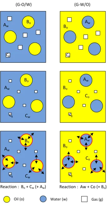
Fig. 1 shows the different processes that occur following Model 1 where the reaction between components A, B and C takes place at the L/L interface. Initially either a G-O/W or G-W/O dispersion is formed. In this case, the gas is partially soluble in the continuous liquid phase, while the reactant in the droplets is not. As a result, component C, which is initially in the gas phase only, migrates into the continuous phase and the bubble size decreases simultaneously. Henry’s law is used to describe the equilibrium concentrations of species, which are distributed between phases. enables to obtain the concentrations of the components in each phase. The concentration of C in the liquid phase increases until a certain limit depending on the gas solubility at the operating pressure and temperature. This leads to a possible reaction occurring between components A, B and C at the interface of the droplet.
Fig. 1. Model 1: reaction occurring at liquid-liquid interface. (i) Initial state. Aw = component A in water; Bo = component B
in oil; Cg = component C in gas. (ii) Partial dissolution of gas in the continuous phase. (iii) The reaction takes place in the
liquid-liquid interface.
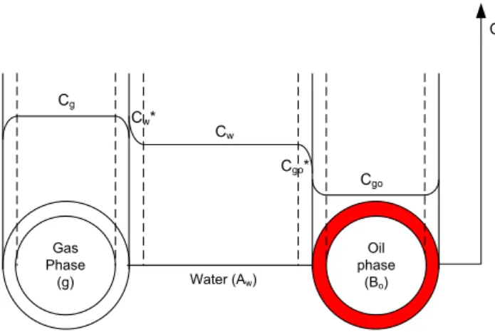
The transport of component C from the bubbles to the L/L interface involves two steps: the first is the mass transfer of C from the gas to the continuous liquid phase and the second is the mass transfer of C from the continuous liquid phase to the interface of the droplets.
Fig. 2 presents the gas mass transfer process in the case of a G-O/W system where the continuous phase is aqueous, where Cgo tends to zero in the case of a chemical reaction consuming C at the L/L interface (in red).
An analogous mass transfer process occurs in G-W/O systems (the water and oil phases are just inverted); component C moves from the bubbles to the oil phase and then from the oil phase to the O/W interface where the reaction takes place.
(G-O/W) (G-W/O)
Oil (o) Water (w) Gas (g)
Bo Aw Cg Bo Aw Cg Cw Co Cw Co Aw Bo Reaction : Bo + Cw (+ Aw) Reaction : Aw + Co (+ Bo) Bo Bo Aw Cg Cg Aw Aw Bo Cg Cg
Fig. 2. Schematic diagram of the mass transfer of component C from the gas bubble via the continuous water phase to an oil droplet and possible concentration profiles (Model 1)
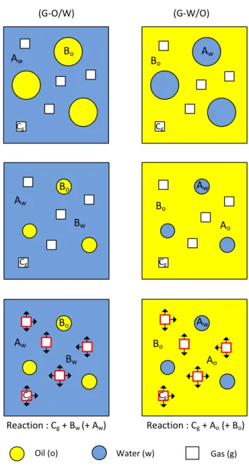
2.2. Model 2: reaction at the G/L interface
Fig. 3 shows the schematic diagram of the processes occurring in the case of a reaction occurring at the G/L interface in a three-phase system. In this configuration, the gas is not soluble in the continuous liquid phase. However, a partial miscibility of the liquid phases enables component B, which is initially present in the dispersed liquid phase, to migrate into the continuous liquid phase, resulting in a decrease of drop size until equilibrium is reached. Component B can then diffuse to the G/L interface, leading to a possible reaction between components A, B and C present in the continuous and gas phases.
In the case of a G-O/W dispersion, the concentration of oil in the continuous phase will depend on its solubility in the aqueous phase. Only the dissolved oil will react with the gas phase at the bubble interface and possibly with other species or a catalyst in the continuous liquid phase (Fig. 4).
Similar phenomena occur in G-W/O systems where oil is the continuous phase. In contrast to the G-O/W system, in a G-W/O dispersion the component in the aqueous phase must be transferred from the water droplet to the gas phase via the continuous oil phase.
Oil phase (Bo) Gas Phase (g) Cg Cw* Cw Cgo Water (Aw) Cgo* C
Fig. 3. Model 2: reaction occurring at the gas-liquid interface. (i) Initial state. Aw = component A in water; Bo = component
B in oil; Cg = component C in gas. (ii) Partial dissolution of dispersed phase in the continuous phase. (iii) The reaction takes
place in the gas-liquid interface.
Fig. 4. Schematic diagram of the mass transfer from an oil droplet via water to a water/gas interface and possible concentration profiles (Model 2)
(G-O/W) (G-W/O)
Oil (o) Water (w) Gas (g)
Bo Aw Cg Bo Aw Cg Bw Ao Bw Cg Ao Cg Reaction : Cg + Bw (+ Aw) Reaction : Cg + Ao (+ Bo) Cg Bo Bo Aw Aw Aw Aw Bo Bo Cg Gas Phase (g) Oil Phase (Bo) CBo CBw* CBw Cg Water (Aw) Cog* C
2.3. Model 3: reaction in the continuous liquid phase
Fig. 5 describes three-phase systems where the reaction occurs in the continuous liquid phase. In this situation, both the gas phase and dispersed phase are partially miscible in the continuous liquid phase. This model is a combination of phenomena occurring in Models 1 and 2, however the reactions principally take place in the continuous phase where all three components, A, B and C, are present.
Fig. 5. Model 3: reaction occurring at the continuous phase. (i) Initial state. Aw = component A in water; Bo = component B
in oil; Cg = component C in gas. (ii) Partial dissolution of dispersion phase in the continuous phase. (iii) The reaction takes
place in the bulk of continuous phase.
In G-O/W systems, both the gas bubbles and oil droplets decrease in size because of the partial dissolution of both oil and gas into the continuous aqueous phase. The dissolved oil and gas enhance both concentrations in this phase and subsequently, the reaction essentially takes place in the bulk. The limiting step in this system is the mass transfer resistance in both the gas/water and oil/water interfaces. Identical phenomena occur in G-W/O systems. Gas and water droplets partially dissolve in the continuous oil phase, where the reaction takes place as indicated by the red arrows in Fig. 5.
(G-O/W) (G-W/O)
Oil (o) Water (w) Gas (g)
Bo B o Aw Aw Cg Cg Cw Bw Co Ao Cw C o Ao Reaction : Cw + Bw (+ Aw) Reaction : Co + Ao (+ Bo) Aw Aw Bw Bo Bo Aw Aw Bo Bo Cg Cg Cg Cg
3. Application to gas-liquid-liquid reactions
Some examples of GLL reacting systems are presented in Table 1. The physico-chemical properties of the system (e.g. solubility, volatility, density, viscosity, miscibility, interfacial tension, wettability with apparatus materials), the operating conditions (e.g. temperature, pressure, relative quantities) and the type of apparatus all play an important role in the type of multiphase system that will be generated, and therefore determine the limiting phenomena that occur [19][20].
3.1. Contacting scheme: Model 1.
Reactions corresponding to Model 1, where reaction essentially takes place at the drop interface, include ozonolysis for synthesis biodiesel/alkyl ester compounds, ozonation of polycyclic aromatic hydrocarbons, as well as hydroformylation of allyl alcohol.
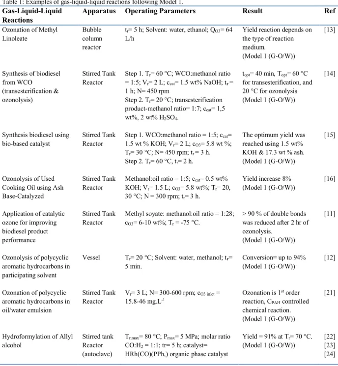
Table 1: Examples of gas-liquid-liquid reactions following Model 1.
Gas-Liquid-Liquid Reactions
Apparatus Operating Parameters Result Ref
Ozonation of Methyl Linoleate Synthesis of biodiesel from WCO (transesterification & ozonolysis)
Synthesis biodiesel using bio-based catalyst
Ozonolysis of Used Cooking Oil using Ash Base-Catalyzed Application of catalytic ozone for improving biodiesel product performance Ozonolysis of polycyclic aromatic hydrocarbons in participating solvent Ozonation of polycyclic aromatic hydrocarbons in oil/water emulsion Hydroformylation of Allyl alcohol Bubble column reactor Stirred Tank Reactor Stirred Tank Reactor Stirred Tank Reactor Stirred Tank Reactor Vessel Stirred Tank Reactor Stirred tank Reactor (autoclave)
tr= 5 h; Solvent: water, ethanol; QO3= 64
L/h
Step 1. Tr= 60 °C; WCO:methanol ratio
= 1:5; Vr= 2 L; ccat= 1.5 wt% NaOH; tr =
1 h; N= 450 rpm
Step 2. Tr= 20 °C; transesterification
product-methanol ratio= 1:7; ccat= 1,5
wt%, 2 wt% H2SO4.
Step 1. WCO:methanol ratio = 1:5; ccat=
1.5 wt % KOH; Vr= 2 L; cO3= 5.8 wt %;
Tr= 30 °C; N= 450 rpm; tr = 3 h.
Step 2. Tr= 60 °C, tr= 2 h.
Methanol:oil ratio = 1:5; ccat= 0.5 wt%
KOH; Vr= 1.5 L; cO3= 5.8 wt%; Tr= 20,
30 °C; N = 300 rpm; tr= 3 h.
Methyl soyate: methanol:oil ratio = 1:28; cO3= 6-10 wt%; Tr = -75 °C.
Tr= 20 °C; Solvent: water, methanol; tr=
5 min.
Vr= 3 L; N= 300-600 rpm; cO3 inlet =
15.8-46 mg.L-1
Tr,max= 80 °C; Pmax= 5 MPa; molar ratio
CO:H2 = 1:1; tr= 5 h; catalyst=
HRh(CO)(PPh,) organic phase catalyst
Yield reaction depends on the type of reaction medium.
(Model 1 (G-O/W)) topt= 40 min, Topt= 60 °C
for transesterification, and 20 °C for ozonolysis (Model 1 (G-O/W))
The optimum yield was reached using 1.5 wt% KOH & 17.3 wt % ash. (Model 1 (G-O/W)) Yield increase 8% (Model 1 (G-O/W))
> 90 % of double bonds was reduced after 2 hr of ozonolysis.
(Model 1 (G-O/W)) Conversion= up to 94% (Model 1 (G-O/W))
Ozonation is 1st order
reaction, CPAH controlled
chemical reaction. (Model 1 (G-O/W)) Yield = 91% at Tr= 70 °C. (Model 1 (G-O/W)) [13] [14] [15] [16] [11] [12] [21] [22] [23] [24]
1. Ozonolysis for biodiesel synthesis
Ozonolysis is an oxidation reaction between ozone, which is a strong oxidizing agent, and an ethylenic compound to form ozonolysis products. Recently, ozone has been used for improving biofuel products produced from free fatty acids (FFA) in edible oils by the splitting the double bonds in the carbon chain in unsaturated FAME (fatty acid methyl ester) to a saturated FAME [11][13][14][15][16]. The reaction scheme is as follows:
Fig. 6. Ozonolysis scheme for biodiesel production.
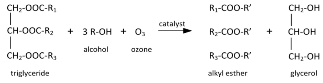
Baber et al. [11] studied the ozonolysis of methyl soyate, consisting of methyl palmitate, methyl stearate, methyl oleate, methyl linoleate, and methyl linolenate. The reaction took place at –75 °C using methanol and methyl soyate as reactants, dichloromethane (solvent) and triethylamine (catalyst). The ozone split the double bond of the carbon chain in the unsaturated methyl ester compound, which then reacts with methanol to give methyl and dimethyl esters products. In just two hours of reaction time, the total number of double bonds in the carbon chain was reduced by more than 90 %. The role of the solvent dichloromethane in this reaction was also investigated. Without dichloromethane in the reaction mixture, the ozonolysis of methyl soyate do not take place. The poor solubility of methyl soyate in methanol at low temperature, which created a two-phase liquid mixture, may be the reason for this observation. At low temperature (–1.6 °C), methyl soyate/methanol solution separated forming two liquid layers. Thus, when the ozonolysis reaction was performed at the low temperature (–75 °C), a separate liquid phase of methyl soyate most likely remained at the bottom of the reaction flask and was unaffected by ozone.
Indeed, there are several challenges associated with this reaction, including a very low reaction temperature (–75 °C), a long reaction time and the large amount of methanol required for the reaction. High yield and conversion can be reached at a molar ratio methyl soyate to methanol of 1:28, whereas ideally 1 mol of unsaturated fatty acid requires 3 mol of methanol to produce the alkyl ester compound, as shown in Fig. 6.
A similar study was carried out by Diaz et al. [13] who performed ozonolysis of methyl linoleate (99 %) in a bubble column reactor at room temperature over 5 hours. The effect of solvent addition (water and ethanol) on the ozonolysis process was also investigated. In their work, the presence of water as a solvent promoted the reaction in different ways: carbonyl oxide reacted with water to form hydroxyl-hydro-peroxide, hydrogen peroxide and aldehyde compounds, and carbonyl oxide reacted with aldehyde compounds to give Criegee ozonide in minor amounts than with the organic solvent. In a more polar medium, greater amounts of ozonide and hydroperoxide are obtained. The yield of the ozonolysis product from unsaturated fatty acids therefore depends on the type of medium where the reaction takes place. The ozonolysis reaction followed the Criegee mechanism comprising of an electrophilic attack by ozone of the double bonds of the carbon chain. It produced 1, 2, 3 trioxolane/primary ozonide, which rapidly decomposed to form carbonyl oxide /zwitterions and carbonyl compounds (aldehyde/ketone). The greatest challenge encountered to achieve high yields of product is mainly related to the solubility of ozone in the liquid solution [25],[26]. Riadi et al. [14] also faced similar difficulties to achieve high yields of the ozonolysis reaction. In their study,
CH2-OOC-R1 CH-OOC-R2 CH2-OOC-R3 + 3 R-OH + O3 R1-COO-R’ R2-COO-R’ R3-COO-R’ + CH2-OH CH-OH CH2-OH catalyst triglyceride alcohol ozone
biodiesel was produced from waste cooking oil (WCO) through simultaneous transesterification– ozonolysis reactions in a stirred tank reactor. The effect of operating parameters (e.g. temperature, type and percentage of catalyst, molar ratio of methanol and oil, stirring speed) were also investigated. The transesterification reaction produced long-chain methyl esters and the ozonolysis reaction gave a short chain methyl ester, resulting from breaking the double bond of the unsaturated fatty acid. However, the reaction yield was low. The challenges associated with performing these reactions are numerous: different temperatures and catalyst types are required to achieve optimum yields of both reactions, the time needed to achieve high yields is very long and most importantly, the low solubility ozone in the solution limits the reactions.
Following the schematic contacting mechanism and mass transfer models presented previously, the ozonolysis reaction follows Model 1 (G-O/W). This can be explained by several facts. Firstly, ozone has greater solubility in an organic solvent than in edible oil [27],[28]. Secondly, ozone is much more reactive with carbon compounds [29],[30] that have double bonds than those with a single bond [11],[31]. For example, the ozonolysis reaction of waste cooking oil (WCO) in Table 1 consists of three-phases: methanol, FFA and ozone [14]. Ozone partially dissolves in methanol and has poorer solubility in WCO. The contact between methanol, which contains dissolved ozone, with WCO, which contains triglycerides, promotes ozonolysis. This mechanism is in agreement with the Criegee mechanism [11],[13] where the ozone reaction with methanol progresses more slowly than that with the reactant with double bonds [32]. The mass transfer steps consist in the dissolution of ozone into methanol followed by the transfer of methanol to the oil phase. It is expected that the ozonolysis reaction takes place at the methanol/oil interface.
2. Ozonation of polycyclic aromatic hydrocarbons
Kornmuller and Wiesmann [21] studied the reaction kinetics of the ozonation of polycyclic aromatic hydrocarbons in an oil/water system in a stirred tank reactor and aimed at improving the gas/water and water/oil mass transfer in order to reduce ozone consumption. With increasing ozone inlet concentration, the ozone mass transfer flux over the interface gas/liquid increased. By increasing stirrer rotational speed, smaller ozone bubbles were formed and were better dispersed in the reaction mixtures, thereby increasing the volumetric mass transfer coefficient. According to Henry’s law, the partial pressure of ozone is directly proportional to the dissolved ozone concentration. At a fixed partial pressure, higher inlet ozone concentrations lead to larger concentration gradients at the methanol/oil interface and consequently mass transfer into the oil phase is improved.
3. Hydroformylation of allyl alcohol
Several authors [22],[23],[24] studied hydroformylation of allyl alcohol by using a n-heptanol-water mixture as a solvent. The catalyst is soluble in the organic phase and the product separates into the aqueous phase, such that there is an effective use of catalyst. HRh(CO)(PPh3)3 was used as a catalyst to synthesize 4-hydroxybutiraldehyde (4-HBA) and 2-metil-3-hydroxypropionaldehyda (2-MHP) from allyl alcohol compound. The reaction is as follows:
Fig. 7. Hydroformylation scheme of allyl alcohol [24]
Three phases are involved hydroformylation reactions: CO and H2 are the gas phase, HRh(CO)(PPh3)3 is dissolved in both the organic phase and in water. The reaction follows the Model 1 (G-O/W). In this reaction, the catalyst allyl alcohol, which is soluble in the organic phase (n-heptanol), and water were introduced into the stirred tank reactor (autoclave) at 70 °C and 5 MPa for 5 hours with CO/H2 molar ratio of 1:1. The reaction occurs at the interface of the organic phase and the products then dissolve into the aqueous phase. The product and the organic phase, which contains the catalyst, are easy to separate and therefore the catalyst can be recycled with a new amount of allyl alcohol to start a new reaction.
The use of a GLL system in this synthesis has proven good catalyst performance for the hydroformylation of allyl alcohol, leading to 91% yield. Another advantage is related to the product separation. However, the presence of aldehyde product in the organic phase will potentially trigger catalyst deactivation because aldehyde interacts with HRh(CO)(PPh3)3, which deactivates it.
3.2. Contacting scheme: Model 2.
Some examples of multiphase reactions that follow Model 2 are described in Table 2. They consist of hydroformylation of olefin compounds, such as propylene and styrene, and the synthesis of pivalic acid from iso- and tert-butanol.
Table 2: Examples of gas-liquid-liquid reactions following Model 2.
Gas-Liquid-Liquid Reactions
Apparatus Operating Parameters Result Ref
Hydroformylation of olefin Hydroformylation of styrenes Carbonylation of benzylchloride Carbonylation of azadienes Tubular reactor with static mixer Mini channel Stirred tank Reactor Stirred tank Reactor ccat= 30 wt% TPPTS, 800 wt, ppm Rh; Lr= 3 m; Din= 17.8 mm; Vr= 0.561 L; tr= 5 s; Tr= 40 °C.
Molar ratio CO:H2 = 1:1; P= 25 bars; Tr=
65 °C.
Tr= 50 – 60 °C; P= 0.1 MPa using
organometallic phase transfer catalysis
Tr= 25 °C; tr= 6 h; P= 1 atm using
organometallic phase transfer catalysis
Selectivity = 99%. (Model 2 (G-O/W)) Conversion = 97%; Yield = 94%. (Model 2 (G-O/W)) Hydrolysis of phenyl acetyl complex is the rate determining step. (Model 2 (G-W/O))
Yield allyl amide= 65%. (Model 2 (G-W/O)) [3] [5] [33] [34] 1. Hydroformylation of olefin CH2 = CH - CH2OH + CO + H2 OHC – CH2 – CH2 – CH2OH 4-HBA CH3 – CH – CH2OH CHO 2-MHP OHC – CH2CH2 – CH2 – OH + H2 HO – (CH2)4 – OH 1,4-butanediol
Hydroformylation is defined as a reaction between olefin compounds with carbon monoxide and hydrogen to produce aldehyde compounds. The olefin compound is an unsaturated hydrocarbon compound having a double bond between the carbon atoms. The reaction has been applied at industrial scale (e.g. the Rhône-Poulenc process); typically, the industrial scale process is performed in a multistage stirred reactor with an efficient heat exchanger due to the high exothermic nature of the reaction. Several researchers have studied the synthesis of aldehyde by hydroformylation reactions in order to improve the process. Weise et al. [3] conducted experiments on the hydroformylation of olefins according the following chemical reaction using continuous flow equipment:
𝐻"+ 𝐶𝑂 + 𝑜𝑙𝑒𝑓𝑖𝑛,-.-/01.2⎯⎯⎯⎯⎯4 𝑅 − 𝐶𝐻𝑂
The reaction was performed in a tubular reactor filled with static mixers (Sulzer SMV) [3]. The olefin is partially miscible in water and the homogeneous catalyst solution used (30 wt% TPPTS, 800 wt. ppm Rh dissolved in pure water) is in excess with respect to the reactants. Firstly, the catalyst solution flow was fed into the olefin flow; this liquid-liquid flow was then mixed with the gas flow (H2 and CO), which was fed into the reactor. The aldehyde product was purified from the catalyst using a settling process. Subsequently, the separated catalyst was directly recycled to the reactor to perform the chemical reaction again.
Purwanto and Delmas [4] performed a similar study on the hydroformylation of 1-octene compound (classified as higher olefin and alpha-olefin) using a catalyst [RhCl (1.5-COD)]2/TPPTS in the aqueous phase. 1-octene is partially miscible in water with very low solubility and is the limiting step in this reaction process. The solubility of 1-octene in the homogeneous catalyst therefore needs to be increased before reacting with H2 and CO gas, in order to obtain a satisfactory yield. Ethanol was therefore added as a co-solvent to enhance octene solubility in the aqueous phase (factor 104 compared with octane solubility without the addition of the co-solvent). However, the presence of ethanol in the aqueous phase caused the formation of acetal, an undesired product. To prevent this, buffer solutions (Na2CO3 and NaHCO3) were added to the homogeneous catalyst phase.
These hydroformylation reactions between olefin/1-octene, TPPTS and Rh in water, H2 and CO gas follow the contacting Model 2 (G-O/W). However, it should be noted that when the reaction is carried out at higher pressure, for example in an autoclave reactor, the solubility of hydrogen gas and carbon monoxide in the liquid phase increases; the gas is then partially dissolved in the continuous phase and the reaction stages will then follow the mechanism of Model 3 (G-O/W) (see Table 3).
The challenges in performing this reaction were related to the partial miscibility of the olefin in the water phase that contains the homogeneous catalyst (TPPTS and Rh), as well as the low solubility of hydrogen and carbon monoxide gas in the water phase [3][5][35]. Typically, in the previous works, reactions were performed in stirred tank reactors with gas-to-liquid or liquid-to-liquid mass transfer limitations. For these reasons, Wiese et al. [3] and Purwanto and Delmas [4] attempt to obtain an optimal reaction product by carrying out the hydroformylation in a tubular reactor equipped with static mixers to increase the surface area between phases or in an autoclave reactor to increase in the solubility of CO and H2 gas in solution.
2. Carbonylation of benzylchloride and azadienes
The carbonylation reaction, shown in Fig. 8, was performed using two types of solvent, including a non-polar organic solvent of diphenyl ether and an aqueous alkali (NaCo(CO)4/Bu4NBr/aq. NaOH) at 0.1 MPa and temperature 50-60 °C [33]. The reaction product was phenyl acetic acid compound soluble into the aqueous phase.
Fig. 8. Carbonylation of benzylchloride.
The catalyst is referred to a phase transfer catalyst (PTC) and plays an important role in facilitating the transport of cobalt carbonyl salt from the aqueous to organic phases. In the organic phase, cobalt was present as cobalt anion and the reaction between the cobalt anion, benzyl chloride and CO gas produced phenyl acetyl complex as an intermediate product. A hydrolysis of phenyl acetyl complex was then performed at the organic-aqueous interface forming phenyl acetyl acid as the final product. At the end of reaction, phenyl acetic acid moves from the organic phase to the aqueous catalyst phase. Based on the previous work, it was observed that the kinetics of the hydrolysis of phenyl acetyl complex is the rate determining step in the synthesis of phenyl acetic acid [33]. Three phases are involved in this synthesis: CO (gas phase), benzyl chloride (organic phase), and NaCo(CO)4/Bu4NBr/aq. NaOH (aqueous phase). The reaction mechanism hence follows the mechanism of Model 2 (G-W/O).
Alper and Amaratunga [34] studied the carbonylation of azadienes with a phase transfer catalyst comprising benzene, water or aqueous NaOH, benzyltriethyl ammonium chloride and cobalt carbonyl as a metal catalyst. The reaction took place in several steps. Firstly, CO gas flows into a mixture of distilled water, benzene and benzyltriethyl ammonium chloride (aqueous phase catalyst); secondly, cobalt carbonyl was added along with methyl iodide; thirdly, this mixture was stirred and azadiene was added with carbon monoxide. The reaction was able to produce allyl amide compound with 65% yield in 6 hours at a temperature 25 °C and 1 atm pressure. A lower yield of 40% was obtained with a shorter reaction time (2 min) and a higher temperature (60 °C).
The three phases involved in this reaction are azadiene soluble in benzene (organic solvent), methyl iodide soluble in water, and CO gas. The carbonylation reaction takes place in the organic phase similar to the carbonylation of benzylchloride above but the reaction product is in the aqueous phase [34]; this reaction follows the mechanism of Model 2 (G-W/O).
3.3. Contacting scheme: Model 3.
Several multiphase reactions following Model 3, including hydrogenation reactions, peroxide hydrogen synthesis, hydrogen synthesis and carboxylation, are presented in Table 3.
Table 3: Examples of gas-liquid-liquid reaction following model 3.
Gas-Liquid-Liquid Reactions
Apparatus Operating Parameters Result Ref
Hydrogenation of α,β-Unsaturated Aldehydes Synthesis of H2O2 via anthraquinone method Synthesis of H2O2 via anthraquinone method Microchannel Coupling process (Oxidation- extraction)-mini-channel Stirred tank Reactor Dcp= 500, 750, 1000 µm; lcp= 3, 6, 12 m; Tr= 60 °C; PH2=1 – 2 MPa
Dimension of flow channel: 15 mm x 2 mm x 3 mm; microfiltration membrane Dpore = 5 µm, thickness =
0.3 mm; Tr= 50 °C; PO2= 200 & 300
KPa
Vr = 1 L; Catalyst: anthraquinone
working solution; Tr= 50 °C; PO2= 1
Volume rate of catalyst phase affect the overall reaction rate & conversion.
(Model 3 (G-W/O))
Conversion= 100% in t< 6.5 s at T= 50 °C. Mass transfer rate significantly increases by the addition of gas phase. (Model 3 (G-O/W)) CH2O2 (product) = 93 mol m-3
in 100 min. [6] [7] [8] CH2Cl + CO NaCo(CO)4 Bu4NBr NaOH CH2COONa + NaCl
Coupling process (Oxidation-extraction) Synthesis of Hydrogen through H2S splitting cycle Carboxylation of olefins Synthesis of Pivalic Acid from Iso- and tert-butanol Hydroformylation of 1-octene Stirred tank reactor Packed bed reactor Stirred tank Reactor (autoclave) Stirrer tank reactor (batch-autoclave) atm; VO/Vw= 200:450; Nagitation= 263
rpm; cEAQH2= 218 mol.m-3; batch
system.
Vr= 300 ml; Nagitation= 100-200 rpm;
Tr= 22 °C; ciodine= 0.1462 mol/L;
molar ratio toluene/water= 80/0.7 cstyrene= 4 M; T= 100 °C; tr= 40 min;
ccat= 2 mol%, cco-cat = 10 mol%
gas-inducing system (ring); 6-blades Rushton turbine; Pmax= 60 bars;
Nagitator= 1800 rpm
Vr= 6x10⁻⁴ m3; Pr= 1.5–2.5x10³ kPa,
Tr= 333-343 K; Nagitation= 23.3 rps;
cat= [RhCl(1.5-COD)]2 with TPPTS
in water.
(Model 3 (G-O/W))
effective interfacial area= 4.03 m2 (at 100 rpm)
(Model 3 (G-O/W)) Conversion= 100%. (Model 3 (G-O/W)) Increasing %volume of 2nd
liquid will increase in the yield (84%).
(Model 3 (G-O/W)) Selectivity= 80%; first order reaction; reaction rate increased with the H2 partial
pressure. (Model 3 (G-O/W)) [9]
[10]
[36] [37]
[4]
1. Hydrogenation of α,β-unsaturated aldehydes
Onal et al. [6] carried out the hydrogenation of α, β-unsaturated aldehyde solution in aqueous multiphase catalysis Ru (II)-TPPTS using a microreactor with a diameter in the range of 500-1000 µm and length from 3.6 m to 12 m. The reaction took place according to the following reaction equation:
Fig. 9. Hydrogenation of α, β – unsaturated aldehyde [6]
The three-phase system consists of an aqueous catalyst phase, an unsaturated aldehyde and hydrogen gas. To carry out the chemical reaction, unsaturated aldehyde and aqueous catalyst were fed through in T-junction resulting in dispersed liquid-liquid flow. At this point, hydrogen was not mixed with the liquid phases, but it was injected into liquid dispersion via a second T-junction. A multiphase dispersed flow pattern as shown in Fig. 10 was formed. The reaction took place at 60 °C and the partial pressure of the hydrogen gas (corresponding to the total pressure in the capillary tube) was in the range of 1.0-2.0 MPa.
The main challenge for performing this reaction in a microreactor is related to the generation of a regular dispersion of the liquid and gas in the continuous phase [38],[39]. The conversion rate was significantly low (around 10%) due to the short mean residence time (2-3 minutes).
Fig. 10. Flow pattern of GLL in channel [6].
R2 R1 O + H2 Ru(II)-TPPTSH2O, solvent R2 R1 OH
Hydrogen gas has very low solubility in the aqueous catalyst phase but shows greater solubility in the organic phase [35]. Since the organic phase has a higher affinity for PTFE (micro channel material), the inner wall of the channel was completely wetted by the organic phase, not the aqueous phase. As a result, when hydrogen was fed to the liquid-liquid phase mixture it formed bubbles in the organic phase (Fig. 10). An increase in the volumetric flow rate of the aqueous phase increased the Reynolds number and the overall mass transfer coefficient [6]. Mass transfer rates at the G/L interface greatly determine the hydrogenation rate and are important to optimize the overall reaction rate. In their study, Onal et al. [6] revealed that an increase up to 1.4 ml.min-1 in the hydrogen flow rate enhanced the rate of the hydrogenation reaction, however beyond this value the reaction rate decreased. Beyond a certain value, an increase in hydrogen flow rate leads to an increase of gas bubbles in the organic phase and this reduces the effective reaction volume and mean residence time in the capillary tube. Another factor that emerges as a limiting step in this reaction is the low value of the activation energy (Ea) when the reaction temperature is high. This condition is triggered by the limited mass transfer occurring in L/L interface, due to the low solubility of water in the organic phase (1.0 g.L–1).
This reaction follows the Model 3 (G-W/O), where the unsaturated aldehyde is the organic phase, the catalyst is in the aqueous phase and hydrogen is gas. The gas solubility in the organic phase is greater than in the catalyst phase, the bubble size therefore decreases and the reaction takes place in the bulk of organic phase.
2. Synthesis of H2O2 via anthraquinone method
Another example of a reaction following Model 3 is the synthesis of hydrogen peroxide. Hydrogen peroxide is one of the best ‘green’ oxidation reactants and it is widely used in the chemical industries and environmental protection.
Fig. 11. Two-stages of hydrogen peroxide synthesis [8]
Synthesis of hydrogen peroxide was performed via two steps (Fig. 11): firstly, 2-ethyl-anthraquinone (EAQ) dissolved in the organic solvent is hydrogenated to form 2-ethyl-anthra-hydroquinone (EAQH2). This is followed by a reactive extraction process, whereby the oxidation of EAQH2 and the extraction of hydrogen peroxide from the anthraquinone solution take place simultaneously.
The three-phase system involved in the second step process included oxygen gas, organic solvent (anthraquinone working solution) and deionized water. The anthraquinone solution was a mixture of 2-ethyl-anthraquinone, trioctyl phosphate and an aromatic C9–C10 compound with a concentration of 120 g.l-1 anthraquinone and a volume ratio of C
9–C10 to the trioctyl phosphate of 3:1. The reaction rate is faster than the extraction rate, so the effects of both reaction and hydrogen peroxide mass transfer on the extraction rate are non-negligible [8].
A means for intensification is the integration of the chemical reaction and separation processes in a single unit. However, it is not easy to develop such integrated processes in industrial practice. The reaction and mass transfer between multiple phases (gas-liquid and liquid-liquid) play an important role in the rate limitations of the process [7][8]. The oxidation rate of EAQH2 itself is strongly influenced by the mass transfer of oxygen through the liquid film and the rate of chemical reaction. Oxygen consumption also varies with volumetric ratios of anthraquinone solution to oxygen, stirring speed and initial concentration of EAQH2. Tan et al. [7] explained that there are two main requirements to improve the efficiency of oxidation and extraction performance: prevent the partial pressure of O2 from becoming too low and ensure significant residence time. This reaction was performed using a micro-dispersion system that employs a 5 µm pore size microfiltration membrane to disperse the fluids.
The contacting mechanism of the three phases involved in the reaction follow Model 3 (G-O/W). Oxygen gas and EAQH2 are both partially soluble in the organic solvent [38], whilst the reaction between oxygen and the EAQH2 occurs in the bulk of organic phase.
3. Synthesis of hydrogen through H2S splitting cycle
Li et al. [9] studied the effect of operating parameters (i.e. the volume ratio of toluene/water, stirring speed and temperature) on the synthesis hydrogen via the H2S splitting cycle. The reaction scheme is as follows:
𝐻"𝑆 + 𝐻"𝑆𝑂8→ 𝑆 + 𝑆𝑂"+ 2𝐻"𝑂 𝐻"𝑆 oxidation 2𝐻"𝑂 + 𝐼"+ 𝑆𝑂"→ 𝐻"𝑆𝑂8+ 2𝐻𝐼 Bunsen reaction
2𝐻𝐼 → 𝐻"+ 𝐼" HI decomposition
The Bunsen reaction is performed at room temperature and the reaction starts with the appearance of two phases, which are poorly soluble. In the process, water is a solvent for the SO2 gas to form a reducible bisulfate anion, however it is also used to ionize HI and H2SO4 compounds. Toluene is employed as an organic solvent for I2. In the next step, SO2 gas is fed into the reactor; the contact of SO2 gas and the liquid triggers the dissolution of gas in both liquids, however the dissolved SO2 concentration is greater in the aqueous phase than in the I2-toluene solution. At the same time, I2 is transferred from the I2-toluene solution to the aqueous phase. The contact between SO2 gas, which is dissolved in the aqueous phase, and I2 initiates the hydrogen producing reaction. Due to the very low solubility of water in toluene, the Bunsen reaction in toluene can be neglected. The Bunsen reaction mechanism in aqueous phase is shown as follows:
𝑆𝑂"+ 𝐻"𝑂 ↔ 𝐻=+ 𝐻𝑆𝑂>? Step 1
𝐻=+ 𝐻𝑆𝑂
>?+ 𝐼"+ 𝐻"𝑂 ↔ 𝐻"𝑆𝑂8+ 2𝐻𝐼 Step 2
This mechanism is supported by the results of [9]: firstly, SO2 was a stable gas with a small reducing capability; secondly, iodine consumption was not observed after contact with the SO2 gas in the I2 -toluene solution; thirdly, the SO2 gas dissolved in water, thereby generating the formation of H2SO4 or a hydrogen bisulphite solution, which has a stronger reduction ability.
The Bunsen reaction is largely determined by the mass transfer of SO2 from the gas phase to the liquid phase. The reaction can be improved in several ways, including enhancement of the stirring process. Higher stirring rates have a positive impact on the reaction rate because it improves mass transfer between water and toluene, since it creates higher interfacial area between the phases. As a comparison, the reaction rate 1.5 times greater at a stirring speed of 300 rpm than with 100 rpm. Other ways to increase the reaction yield is by increasing the volume ratio of the toluene to liquid mixture, by increasing the partial pressure of SO2, and by increasing the iodine concentration in the I2-toluene solution.
The contacting mechanism between SO2 gas, I2-toluene solution and water in this synthesis follows Model 3 (G-O/W). SO2 gas and I2 are both partially soluble in water. The synthesis of hydrogen takes place in the bulk of continuous water phase.
4. Carboxylation of olefins
The synthesis of cyclic organic carbonate was performed via oxidation and carboxylation reactions [10]. Several possible reactions schemes exist for this synthesis as shown in Fig. 12; the sequential epoxidation-carboxylation (Fig. 12(a)) scheme is the most probable.
(a) (b)
(b)
(c)
Fig. 12. Reaction strategies for the synthesis of cyclic organic carbonate (a) Sequential oxidation and carboxylation, (b) Simultaneous oxidation and carboxylation, (c) Carboxylation via oxy-bromination [10].
The main challenge for performing both reactions simultaneously is related to the specific needs of each reaction. Hydrogen peroxide is usually chosen as an oxidant because epoxidation will produce water only as a by-product. However, hydrogen peroxide is not an appropriate oxidant for carboxylation, which typically requires a Lewis base as a catalyst. Moreover, the presence of water as a by-product in the system triggers a two-phase epoxidation reaction because olefin is hydrophobic. In order to reach sufficient reaction yield, a long reaction time is required due to the fact that SO2 is completely soluble in water (2000 mg/L) [40] and therefore mass transfer, from water (aqueous phase) to olefin (organic phase), takes much longer. The rate of mass transfer in this stage is hence the limiting step.
The reaction strategy chosen above involved methyltrooxorhenum (MTO) as a catalyst to epoxidize olefin (styrene) to styrene oxide, and then an amino trisphenolate complexed aluminum catalyst with a tetrabutylammonium iodide (TBAI) co-catalyst to convert styrene oxide into styrene carbonate. The study focuses on the carboxylation reaction involving a three-phase GLL system comprising a catalyst and co-catalyst that are soluble in the solvent, styrene oxide and CO2 gas.
As for the epoxidation reaction, carboxylation is conducted via the following steps: first, styrene and oxidant were introduced into the epoxidation reactor to produce the epoxide compound. The product was then separated from the excess of hydrogen peroxide entering the carboxylation reactor. The aqueous phase, which contains the hydrogen peroxide, and the epoxide product in the organic phase are then separated. Next, the organic phase is mixed with a Lewis base catalytic system; this solution is then mixed with CO2 gas. A segmented gas-liquid flow then entered the carboxylation reactor.
Sathe et al. [10] used a packed bed flow reactor, which offers enhanced interfacial area and also safer control of the reaction. It also eliminated the needs for a pressurized vessel to maintain constant pressure in headspace above the reaction mixture. The use of a flow reactor was an appropriate
solution for the sequential carboxylation epoxidation using mutually incompatible reagents, which are introduced in the reactor at different points (spatially and temporally). This sequential operation enabled a yield of styrene oxide-to-styrene carbonate of 88% for a residence time of 30-40 min. This synthesis follows the contacting Model 3 (G-O/W) between CO2 gas, a Lewis base catalyst and an organic compound. The CO2 gas and the Lewis base catalyst are partially soluble in the organic compound. The combination of the cyclic organic carbonates occurs in the bulk of the organic phase. 5. Synthesis of pivalic acid from iso- and tert-butanol
The synthesis of pivalic acid is generally characterized by the presence of two liquid phases and a gas phase with a parallel/consecutive reaction scheme where both the main and side reactions are fast. The oligomerization side reaction and the consecutive reaction consists of isomerization, disproportionation and carbonylation, producing a higher acid product with a longer carbon chain.
In the Koch synthesis [36], pivalic acid can be produced from iso- and tert-butanol with CO gas and water as reactants, using sulfuric acid as a catalyst. 2-methyl butanoic acid is the main by-product. (𝐶𝐻>)"𝐶𝐻𝐶𝐻"𝑂𝐻 + 𝐶𝑂 + 𝐻"𝑂 → (𝐶𝐻>)>𝐶𝐶𝑂"𝐻
Isobutanol 2-methyl butanoic
Brilman et al. [36] used an autoclave reactor at high operating pressure to obtain a reaction yield of 84% for the synthesis of pivalic acid from iso- and tert-butanol. The use of the autoclave reactor pressurized up to 60 bars and equipped with a gas-inducing impeller at high stirring speed (1800 rpm) enabled an increase in mass transfer and improvement of gas solubility during the reaction. The selectivity of pivalic acid was increased by reducing acidity and temperature, and by increasing the pressure of CO.
The technological challenges related to this reaction are similar to the previous case and are related to the solubility of the three separate phases, which must be in contact for the reaction to occur. The droplets of iso- and tert-butanol dissolve partially in the continuous phase, however the gas does not dissolve in the droplets or the continuous phase. In Models 1, 2, and 3, it is assumed that there neither the dispersed or continuous liquid phases are soluble in the gas phase. In Model 3, the partial solubility of the liquid and gas phases in the continuous phase is the decisive step. It is therefore evident that by increasing the solubility of the dispersed phases in the continuous phase, the reaction occurring in the bulk continuous phase will be enhanced.
Brilman et al. [37] also studied the synthesis of pivalic acid/carboxylic acid using other reactants comprising CO gas, iso-butene, tert-butanol, catalyst solution and heptane, as a second immiscible liquid. This was carried out under pressure (40 bars) in an autoclave reactor for 1 hour using an acid catalyst H2SO4 96 wt%. The CO gas, iso-butene and tert-butanol dissolved in heptane were firstly contacted with the H2SO4 catalyst. CO, iso-butene, and tert-butanol were then transported to the catalyst phase due to partial solubility. The reaction then took place in the catalyst phase and the product formed was extracted by heptane.
The effects of reactant feed rate, location of the gas injection, stirring rate and the presence of an immiscible liquid phase on the total acid yield and product distribution were studied. At low reactant flow rate, oligomer formation is suppressed and the selectivity of pivalic acid increases, whilst the selectivity of acid products with longer carbon chains decreases. The solubility of CO into the catalyst phase is still relatively low (1.5x10²mol/m3 at 40 bars and 293 K) and therefore only yields 25% of pivalic acid. To achieve higher yields, two points must be considered: the flow rates of CO gas and alkene, and the mass transfer of CO gas. In addition, acid yield will increase with increasing agitation speed. An alternative choice for the second liquid in the system also has positively impacts reaction yield. In this study, the yield and selectivity of pivalic acid both depend on the volume of heptane used; higher volumes of heptane enable an increased capacity of CO gas dispersion. Heptane was
chosen as an immiscible organic liquid phase since CO solubility in heptane is 3.5 times greater than in the catalyst solution [35], and CO gas does not react with heptane. The reaction of carboxylic acid follows Model 3 (G-O/W) with CO as the gas phase, a hydrocarbon soluble in heptane as the organic phase and an acid catalyst as the aqueous phase.
4. Discussion
4.1- Effect of hydrodynamics and choice of process technologies
Since mass transfer between the gas-liquid phases and liquid-liquid phases is directly related to the interfacial surface area, the size of the gas bubbles and the droplets has a significant effect on the efficiency of the process. Generally, all systems that lead to a decrease in the characteristic size of the bubbles and drops will be beneficial to reaction efficiency. However, a simple decrease in bubble or drop size is not the only factor that may influence the reaction performance. Several other competing phenomena may also occur, e.g. the diffusion of a reactant at the interface and the chemical reaction. The relative rates of the competing phenomena control where the reaction takes place and therefore it is of major importance that the different phenomena occurring in the considered reaction be identified. The Hatta number (Ha)[41] expresses the relative magnitudes of rate of reaction and the rate of physical mass transfer, and in particular, the rate of reaction in an interfacial film to the rate of diffusion of species through the film. Practically, it enables identification of where the chemical reaction occurs in a heterogeneous medium.
𝐻𝑎 = E Rate of reaction of A in the film per unit surface area Rate of mass transfer of A through the film per unit surface areaX
Y " Z
The literal expression of Ha depends on the kinetics and interfacial models used, however three regimes can be identified.
• For Ha <0.3, the reaction is much slower than mass transfer of the species from the dispersed phases, so the reaction takes place in the continuous bulk;
• For Ha> 3.0, the reaction is much faster than mass transfer of the species from the dispersed phases, so the reaction takes place at the interface;
• For 0.3 <Ha <3.0, the reaction rate is of the same order of magnitude as the rate of mass transfer from the dispersed phases, so the reaction may take place in both the bulk and at the interfaces.
Although Ha was initially defined for reactive gas-liquid systems, it can also be used for two-phase liquid-liquid reactions. In the case of reactive GLL systems, Ha can be defined with respect to the species that must be transported through the gas-liquid and liquid-liquid interfaces to react, i.e. reactant C, which is initially present in the gas phase, and the reactant present in the dispersed liquid phase (A for G-W/O system or B for G-O/W system).
In the case of GLL reactions, Ha will control the reaction depending on the reaction system. For reactions following Model 1, the limiting step is the diffusion of the reactant in the dispersed liquid phase and therefore Ha at the liquid-liquid interface will control the reactive system. For those that follow Model 2, the limiting step is the diffusion of the gas into the liquid so Ha at the gas-liquid interface controls the system. Finally, for Model 3 reactions, the rates of diffusion of the reactants from both the dispersed gas and liquid phases are of the same order of magnitude and therefore Ha can be calculated for both the gas-liquid and liquid-liquid interfaces. From the above, it is clear that
for each GLL reaction, the appropriate physical model that correctly defines the limiting steps must firstly be identified. Following this, specific process equipment and operating conditions can then be chosen such that they are adapted to the reaction requirements.
Stirred tank reactors can be a pertinent equipment choice for many reactions provided they are fitted with appropriate impeller types and correctly designed (e.g. use of baffles, correct choice of off-bottom impeller clearance, liquid height). For continuous processes, stirred tanks remain a good choice, even if packed columns or tubes equipped with static mixers are also well adapted for fast reactions and low coalescing systems. Continuous miniaturized flow reactors are also an alternative to the traditional stirred tank reactor for reactions that are highly limited by heat and/or mass transfer, or that employ hazardous products. In such continuous flow equipment, the residence times are generally short and therefore are better adapted to fast reactions. Due to the high surface to volume ratio (and therefore increased surface effects) of such equipment, the continuous phase is often determined by the wettability of the reactor wall by the liquids.
Model 1 describes a system where the reaction takes place at the liquid-liquid interface. In this case, the Hatta number is small (Ha<0.3) and therefore the reaction is fast compared with the solubility of the reactant (initially contained in the drops) in the continuous liquid phase. Due to the consumption of the reactants by the chemical reaction, an acceleration of mass transfer at the liquid-liquid interface is expected. It is therefore important to generate small drops such that the surface area for mass transfer is maximized. Moreover, in order to renew the liquid at the drop interface and increase mass transfer, turbulent flow conditions are required. For batch or continuous processes, a stirred tank equipped with a high shear impeller, e.g. rotor-stator, which will promote drop breakup, in combination with an axial flow impeller, which will ensure global circulation in the tank, would be well adapted. The dissolution of the gas in the continuous liquid phase is generally simple to achieve and therefore the means in which the gas is injected in the liquid has little influence; a simple ring sparger is typically used in stirred tanks. One of the examples described in section 3 “Application to Gas-liquid-liquid reactions” shows that an increase in stirrer rotational speed induces an increase in reaction yield (ozonolyse reaction [21]). This is due to the impact of the rotational speed, which promotes the creation of smaller droplets and also increases turbulence, both of which enhance mass transfer.
In Model 2, the reaction occurs at the gas-liquid interface. This configuration corresponds to a high value of the Hatta number (Ha>3) and the success of the process is strongly linked to the bubble size. Since the solubility of the liquid droplet into the continuous phase is not a problem, the size of the droplets is not a limiting factor. Small bubbles can be generated by the use of disc turbines, e.g. Rushton turbines or concave blades turbines (which enable improved gas handling), and by correctly choosing and implementing the gas sparger. Different sparger types exist, including ring and flat geometries; a simple tube sparger is not however recommended. If the reaction kinetics are slow, it is important to increase the residence time of the gas phase by using a stirred tank with a height much larger than the diameter of the tank. In this case, multiple impellers on the shaft should be used. The turbulence created in the tank will also promote the reaction by renewing the gas-liquid interface. For this model, as well as for Model 1, the location of the agitator at the beginning of the operation is crucial since, depending on the range of interfacial L/L tension and viscosities of the system, it may determine which phase will be dispersed in the other (O/W or W/O). Generally, the agitator should initially be located in the phase that is expected to be the continuous one. In the case where the dispersed phase is fed into the continuous phase, it should be added at the surface if it is denser than the continuous phase or in the impeller outflow if it is lighter than the continuous phase.
In Model 3, the solubility of the gas and of the dispersed liquid in the continuous phase is high. Furthermore, the reaction is slow and occurs in the continuous phase, corresponding to intermediate Hatta numbers (0.3<Ha<3). In this case, the residence time is the controlling parameter of the process and the influence of the bubble and drop size is less important than in the other two models. A stirred tank reactor is well adapted to this scenario. The recommended impeller type for such an operation would be a disc turbine or pitched blade turbine since these are effective for bubble and drop generation (see for example the synthesis of pivalic acid [37]), as well as for global mixing of the system. Gas should be fed into the system through a ring or plate sparger.
4.2 Effect of the pressure
Increasing the pressure of the reacting system is particularly interesting when the solubility of the gas in the continuous phase is the limiting step. Gas solubility increases with pressure and therefore the reaction yield can be enhanced by operating under pressure. For example, in the hydroformylation reaction that was carried out in an autoclave reactor [4], an increase in the partial pressure of hydrogen increased the solubility of hydrogen and carbon monoxide in the continuous liquid phase and reaction contacting mechanism changed from Model 2 to Model 3. Other examples of reactions that report the effect of the pressure on the yield of reactions are given in [10] and [36].
5. Conclusion
To effectively perform a GLL reaction, the contacting mechanism responsible for its enhancement should be known. In this analysis, three phase contacting models that represent the contacting mechanisms between phases for water-in-oil or oil-in-water systems with a gas have been presented. The proposed models are based on mass transfer that can occur between the three different phases.
From the reaction mechanisms illustrated by the contacting models, it is obvious that the gas-liquid-liquid reactions will proceed if the interphase mass transfer is effective. Mass transfer occurs from the dispersed gas phase to the continuous liquid phase and/or from the dispersed liquid phase to the continuous liquid phase and can be promoted by employing correctly adapted process equipment and the associated operating conditions, such that the phases are dispersed in the right manner and interfacial area and turbulence are increased. However, depending on the contacting mechanism required by the reaction type, different equipment and operating conditions should be chosen to enhance reaction performance. Model 1 corresponds to fast reactions that occur at the liquid-liquid interface. In this case, it is important to promote mass transfer by increasing the surface area of the droplets and create turbulent flow conditions in order to renew the liquid-liquid interface. Model 2 corresponds to GLL systems where by the solubility of the dispersed liquid in the continuous phase is high and the reaction takes place at the gas/liquid interface. In this case, bubble size is the parameter that limits mass transfer so it is important to choose equipment and conditions that promote high gas/liquid interfacial areas and bubble breakup. Model 3 corresponds to slow reactions occurring in the continuous liquid phase in which the solubility of the dispersed gas and liquid phases is high. In this case, the residence time (or the operating time) is the controlling parameter for reaction performance, whilst the size of the bubbles and droplets in less important.
Acknowledgements
AYW acknowledges financial support from the Indonesia Endowment Fund for Education (LPDP), Ministry of Finance; and the Directorate General of Higher Education (DIKTI), Ministry of Research, Technology and Higher Education, Republic of Indonesia.
References
[1] Octave Levenspiel, Chemical Reaction Engineering, third ed., John Wiley & Sons, New York, 1999. [2] Raminder Kaur, M. Ramakrishna, K.D.P. Nigam, Indian Institute of Chemical Technology Communication no. 070204. 23 (2007) 3-4.
[3] Klaus-Diether Wiese, Oliver Moller, Guido Protzmann, Martin Trocha, Catalysis Today. (2003) 79-80, 97-103.
[4] P. Purwanto, H. Delmas, Catalysis Today. 24 (1995) 135-140.
[5] Sivarajan Kasinathan, Samuel L. Bourne, Paivi Tolstoy, Peter Koos, Matthew O Brien, Roderick W. Bates, Ian R. Baxendale, Steven V. Ley, Synlett. 18 (2011) 2648-2651.
[6] Yucel Onal, Martin Lucas, Peter Claus, Catalysis. Chem. Eng. Technol. 28 (2005) 9. [7] J. Tan, C. Dong, Y. C. Lu, J. H. Xu, G. S. Luo, Ind. Eng. Chem. Res. 51 (2012) 1834-1845. [8] Shuxiang Lu, Li Wang, Yaquan Wang, Zhentao Mi, Chem. Eng. Technol. 34 (2011) 823-830 [9] Ji Li, Armin Moniri, Hui Wang, International Journal of Hydrogen Energy. 40 (2015) 2912-2920. [10] Ajay A. Sathe, Anirudh M. K. Nambiar, Robert M. Rioux, Catal. Sci. Technol. 7 (2017) 84-89
[22] Anil G. Panda, Sachin R. Jagtap, Nitin S. Nandurkar, Bhalchandra M. Bhanage, Ind. Eng. Chem. Res. 47 (2008) 969 – 972.
[11] Tylisha M. Baber, Daniel Graiver, Carl T. Lira, Ramani Narayan, Bio-macromolecules. 6 (2005) 1334-1344.
[12] Anna Lundstedt, Matthew J. Webb, Helena Grennberg, Royal Society of Chemistry. 7 (2017) 6152-6159. [13] Maritza F. Diaz, Frank Hernandez, Oscar Ledea, Jose A. Gavin Sazatornil, Jesus Moleiro, Ozone Science
& Engineering. 25 (2002) 121-126
[14] Lieke Riadi, Aloysius Yuli Widianto, Edy Purwanto, Akso Pono, Ruth Theresia, Journal of Chemical and Pharmaceutical Research. 7 (2015) 17-21.
[15] Lieke Riadi, Edy Purwanto, Hendrik Kurniawan, Ria Oktaviana. Procedia Chemistry. 9 (2014) 172-181. [16] Lieke Riadi, Edy Purwanto, Melisa, Yogi Chandra, International Journal of Engineering & Technology
IJET-IJENS. 12 (2012) No 6, 87-90.
[25] Rakovsky S., Anachkov M., Belitskii M., Zaikov G, Chemical & Chemical Technology. 10 (2016) No. 4(s).
[26] Qizhou Dai, Liling Chen, Shijie Zhou and Jianmeng Chen, Organics in Aqueous Solution. Royal Society of Chemistry. 5 (2015) 24649-24654.
[31] B.E. Krisyuk, A. V. Maiorov, and A.A. Popov, Kinetics and Catalysis. 57 (2016) No. 3, 326-332. [29] Peter Dowideit, Clemens V.S., Environ. Sci. Technol. 32 (1998) 1112-1119.
[30] Sidney Toby, Frina S. Toby., J. Phys. Chem. A. 102 (1998) 4527-4531.
[38] V. M. Rajesh, Vivek V. Buwa, Chemical Engineering Journal. (2012) 207-208, 832-844.
[35] U.J. Jauregui-Haza, E.J. Pardillo-Fontdevila, A.M. Wilhelm, H. Delmas, Latin American Applied Research. 34 (2004) 71-74.
[23] R. V. Chaudhari, A. Seayad, S. Jayasree, Catalyst Today. 66 (2001) 371-380.
[39] Jun Yue, Evgeny V. Rebrov, Jaap C. Schouten, Royal Society of Chemistry. 14 (2014) 1632-1649.
[17] Andrian Wegmann, Julia Melke, Philipp Rudolf von Rohr, International Journal of Multiphase Flow. 33 (2007) 484-497.
[19] AgnieszkaLadosz, Eugen Rigger, Philipp Rudolf von Rohr, Microfluid Nanofluid. (2016) 20:49.
[20] Zhenzhong Wen, Xinhai Yu, Shan-Tung Tu, Jinyue Yan, Erik Dahlquist, Bioresource Technology. 100 (2009) 3054-3060.
[32] Justyna Sadowska, B. Johansson, E. Johannessen, R. Friedman, L. Broniarz-Press, J.B. Rosenholm, Chemistry and Physics of Lipids. 151 (2008) 85-91.
[21] Anja Kornmuller, Udo Wiesmann, Water Research. 37 (2003) 1023-1032.
[27] Hiroshi Miyamoto, Yuri Yampolski, Colin L. Young, J. Phys. Chem. Ref. Data. 43 (2014) no. 3. [36] D.W.F. Brilman, W. P. M. van Swaaij, G. F. Versteeg, Chem. Eng. Sci. 54 (1999) 4801-4809.
[33] L. Cassar, M. Foa, Journal of Organometallic Chemistry. 134 (1977) C15-C16. [34] Howard Alper, Shiyamalie Amaratunga, Can J. Chem. 61 (1983) 1309 – 1313.
[24] Raj M. Deshpande, Sunil S, Divekar, Bhalchandra M. Bhanage, Raghunath V. Chaudhari, Journal of Molecular Catalysis. 75 (1992) L19-L22.
[18] D.W.F. Brilman, M. J. V. Goldschmidt, G. F. Versteeg, W. P. M. van Swaaij, Chem. Eng. Sci. 55 (2000) 2793-2812.
[28] Andrzej K. Bin, Ozone: Science & Engineering. 28 (2006) 67-75.
[37] D.W.F. Brilman, N.G. Meesters, W.P.M. van swaaij, G.F. Veersteeg, Catalysis Today. 66 (2001) 317-324. [40] Praxair, Carbon dioxide safety data sheet P-4574, Octobre 2016
[41] S. Hatta, Technological Reports of Tôhoku University, 10 (1932) 613-622. Nomenclature A chemical component B chemical component c concentration (mol %) C chemical component D diameter (m) G gas l length (m) L liquid N stirring speed (s-1) O oil P pressure (Pa) Q flow rate (m3.s-1) t time (s) T temperature (°C) V volume (m3) W water Subscripts cp capillary pipe r reactor

![Fig. 9. Hydrogenation of α, β – unsaturated aldehyde [6]](https://thumb-eu.123doks.com/thumbv2/123doknet/14272764.490572/15.892.103.781.108.474/fig-hydrogenation-α-β-unsaturated-aldehyde.webp)
![Fig. 11. Two-stages of hydrogen peroxide synthesis [8]](https://thumb-eu.123doks.com/thumbv2/123doknet/14272764.490572/16.892.280.659.644.844/fig-stages-hydrogen-peroxide-synthesis.webp)
