READ THESE TERMS AND CONDITIONS CAREFULLY BEFORE USING THIS WEBSITE.
https://nrc-publications.canada.ca/eng/copyright
Vous avez des questions? Nous pouvons vous aider. Pour communiquer directement avec un auteur, consultez la première page de la revue dans laquelle son article a été publié afin de trouver ses coordonnées. Si vous n’arrivez pas à les repérer, communiquez avec nous à PublicationsArchive-ArchivesPublications@nrc-cnrc.gc.ca.
Questions? Contact the NRC Publications Archive team at
PublicationsArchive-ArchivesPublications@nrc-cnrc.gc.ca. If you wish to email the authors directly, please see the first page of the publication for their contact information.
NRC Publications Archive
Archives des publications du CNRC
This publication could be one of several versions: author’s original, accepted manuscript or the publisher’s version. / La version de cette publication peut être l’une des suivantes : la version prépublication de l’auteur, la version acceptée du manuscrit ou la version de l’éditeur.
Access and use of this website and the material on it are subject to the Terms and Conditions set forth at
A Critique on the Building of Decentralized Manufacturing Control
Systems with UML Capsules
Fletcher, M.; Brennan, R.W.; Xu, Y.; Norrie, D.H.
https://publications-cnrc.canada.ca/fra/droits
L’accès à ce site Web et l’utilisation de son contenu sont assujettis aux conditions présentées dans le site LISEZ CES CONDITIONS ATTENTIVEMENT AVANT D’UTILISER CE SITE WEB.
NRC Publications Record / Notice d'Archives des publications de CNRC:
https://nrc-publications.canada.ca/eng/view/object/?id=7d2eb087-1032-49d6-a85b-2f65b9d752a5 https://publications-cnrc.canada.ca/fra/voir/objet/?id=7d2eb087-1032-49d6-a85b-2f65b9d752a5
National Research Council Canada Institute for Information Technology Conseil national de recherches Canada Institut de technologie de l’information
A Critique on the Building of Decentralized
Manufacturing Control Systems with UML
Capsules *
Fletcher, M., Brennan, R.W., Xu, Y., and Norrie, D.H.
November 2001
* published in Proceedings of the IASTED International Conference on Intelligent Systems and Control, Clearwater, Florida. November 19-22, 2001. pp. 43-48. NRC 44932.
Copyright 2001 by
National Research Council of Canada
Permission is granted to quote short excerpts and to reproduce figures and tables from this report, provided that the source of such material is fully acknowledged.
A CRITIQUE ON THE BUILDING OF DECENTRALIZED MANUFACTURING
CONTROL SYSTEMS WITH UML CAPSULES
M. FLETCHER1, R.W. BRENNAN2, D.H. NORRIE2, Y. XU2
1
Institute for Manufacturing, University of Cambridge Mill Lane, Cambridge CB2 1RX, United Kingdom
Email: mf283@eng.cam.ac.uk
2
Department of Mechanical and Manufacturing Engineering, University of Calgary,
2500 University Drive NW, Calgary, Alberta T2N 1N4, Canada. Email: brennan@enme.ucalgary.ca
Abstract: In this paper, we describe two orthogonal methodologies for building decentralized manufacturing control systems. The fundamental building block of these control systems is the UML capsule stereotype that can be used to design object-oriented software systems that are open, agile, have capacity to manage real-time tasks and so can provide varying degrees of ‘intelligence’ within a 21st century manufacturing environment. We also critique and evaluate the merits of these two viewpoints with respect to how responsive the manufacturing control system is to requests for reconfiguration.
Keywords: decentralized manufacturing control systems, real-time reconfiguration, UML capsule stereotype.
1 INTRODUCTION
In developing decentralized manufacturing control systems the new International Electro-technical Committee’s architecture for industrial process control and measurement systems is receiving concerted attention from the academic and vendor communities. This architecture (numbered IEC 61499) focuses on function blocks and how they operate within an open environment containing distributed hardware controllers upon which the function blocks can execute their control/measurement algorithms. Moreover, the architecture provides a solid foundation to construct the systems needed by manufacturing businesses for 21st century production where batch sizes are decreasing, response times are getting shorter and the need to minimize wasted resources is even more paramount than today. Unfortunately as yet, no coherent analysis and modeling philosophy exists to underpin the building of decentralized control systems required for this new breed of manufacturing. One proposal to redress this imbalance is to model the control system at a conceptual level using well-established object-oriented technologies (such as UML) and then map these concepts onto function blocks to facilitate execution in the real-world environment.
With IEC 61499, the function block can be thought of in terms of an “enhanced” object. Like recent object-oriented and agent-based models for manufacturing system
control, the IEC 61499 function block shares many of the characteristics of the traditional objects and agents used to develop these applications. For example, a traditional object focuses on data abstraction, encapsulation, modularity and inheritance, while agents concentrate on artificial intelligence, modeling each other and inter-agent cooperation. The function block is enhanced through its recognition of two very specific kinds of messages: data
messages (which one would expect of a traditional object)
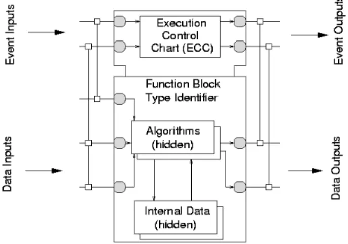
and event messages (which are used to schedule the execution of a function block’s algorithms). The resulting focus on process abstraction and synchronization makes this approach particularly suitable for control of an “intelligent” real-time manufacturing environment that is concurrent, asynchronous and distributed. An example of an IEC 61499 function block is shown in Figure 1. For economy of this paper, we do not discuss how the function block operates – we refer interested readers to [1].
Figure 1: IEC 61499 Function Block Model.
As previously stated, we intend to model the elements of a function block using the Unified Modeling Language (UML). The Real-Time Unified Modeling Language (RT-UML) was developed to deal with software systems that are characteristically time-critical, complex, event-driven and distributed. When using RT-UML to develop this type
of manufacturing control system, a key concern is the architecture (or structural and behavioral framework) of the software operating within this system. Recently, when confronted with the problem of designing such a system with oriented or agent-based philosophies, object-oriented analysis and design (OOAD) in combination with the UML has proven to provide an efficient methodology to support system development. The RT-UML can be thought of as an extension of UML, or in other words, it provides a library of applied UML concepts that can be used for modeling the next generation of decentralized manufacturing control systems [2][3][4]. To support the design of such systems, the real-time version of UML (RT-UML [5]) adds three new concepts to (RT-UML:
1. Capsule: A concurrent, active software entity that can display location transparency across a number of hardware controllers in a manufacturing environment. Each capsule has associated member functions (behaviors) and attributes, with varying degrees of scope, to facilitate interaction. Capsules interact with both each other and the controlled manufacturing processes (probably in their local vicinity) through one or more signal-based boundary objects called ports. A private state transition machine is used to handle faults and manage the execution of a capsule’s functionality. Note that a capsule is an existing UML stereotype with suitable extensions to support real-time behavior. 2. Port: An object that implements a specific interface
into and out of the capsule. A port mediates a capsule's interaction with the outside world, and there can be several ports per capsule depending on the distinct interaction roles the capsule has with external beings. 3. Connector: Abstract communication channels that
connect two ports and provide flexible mechanisms to “glue” together capsules into a dynamic structure. Via these concepts, the environment and internal configuration of the capsule are decoupled from how the capsule is used. This leads to a higher degree of re-use for the capsules during software development cycles. The connections between ports illustrate how one capsule can affect others via direct communication. Recursive sub-capsules are possible, so a hierarchy of sub-capsules can be used to model individual function block algorithms, execution control states or data values. Thus capsules solve many of the problems faced during the development of our particular genre of real-time software [6] by combining: • UML as a general-purpose software and business
system analysis and design approach.
• A language for visually representing software elements and how they interact in real-time. The Real-Time Object-Oriented Modeling (ROOM) language [8] is a suitable candidate to support this functionality. It also has some formal semantics to ensure properties, such as termination, can be obtained [10].
• Role modeling to represent communication and design patterns between the software entities in a distributed
process control system [7][9], e.g. role modeling helps specify collaboration along related connectors, and requirements for timing /sequencing among capsules. In this paper we critique and evaluate how IEC 61499 function blocks can be modeled using UML capsules for building decentralized manufacturing control systems.
2 CONTROL SYSTEM SCENARIO
In order to illustrate the merits of our approach and make the paper more readable, we introduce a simple concrete example that runs through the remainder of the paper. This scenario is typical of the functionality found in the next generation of decentralized manufacturing control systems. The system administrates the reporting of sensor failures to the user through the application of three function blocks:
E_CTU (an event counter to record the number of periodic
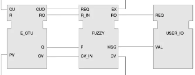
times a given sensor has failed to measure its assigned metric); USER_IO (to write reports on minor failures to a log file and send reports of major faults to the user’s mobile phone); and FUZZY (to make decisions, based on some progressive non-binary rules, of how bad sensor failures are). The aggregation (one per sensor) of these function blocks is illustrated in Figure 2.
Figure 2: Function Blocks in Sensor Control System.
FUZZY sets a pre-defined limit on the number of sensor failures by issuing an output event and output data value (received as a CU input event with attached value PV at E-CTU). When the number of failures equals PV then E_CTU informs FUZZY by issuing an appropriate output event (CUO) and output data values (i.e. Q and CV). FUZZY then resets the counter by sending an output event that is received as an R input event by E_CTU. FUZZY uses this knowledge and its internal fuzzy logic to determine whether to issue a minor or major report. Once determined, it informs (via suitable output data and events) USER_IO to dispatch a warning in an appropriate fashion.
Here we focus on the event counter function block that records the number of missed readings by a sensor and issues an event if a pre-defined number of failures occur. Figure 3 shows the interface and execution control chart for the IEC 61499 standard’s E_CTU function block. This function block has the same basic functionality as the “count up” function block used in common PLC ladder logic: i.e. the CU event causes the COUNT algorithm to increment CV by one (CV: = CV + 1) and set Q to TRUE if PV is reached (Q: = (CV ≥ PV)).
Figure 3: The IEC 61499 E_CTU Function Block.
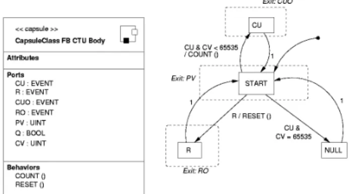
An equivalent specification of the E_CTU function block, written in RT-UML notation, is shown in Figure 4.
Figure 4: RT-UML Equivalent of E_CTU.
Figure 4(a) depicts the capsule’s class name and its public interface in terms of its attributes, ports and behaviors. In Figure 4(b), state action properties are specified by an event condition, a slash (“/”), and an action list. As well, entry and exit actions for nested states are also specified. For example, the transition from state “START” to state “CU” involves first reading the current value of PV (“START” exit action), then executing COUNT (transition action). Before the state returns to “START”, CUO is set (“CU” exit action). We now explore two design methodologies to map function blocks to capsules.
3 DESIGN METHODOLOGIES
The IEC 61499 and RT-UML modeling concepts share many similarities, and there is a clear correspondence between IEC 61499 concepts and RT-UML capsules. Also, IEC 61499 data and event interfaces and RT-UML ports are similar, as are IEC 61499 execution control charts and RT-UML state transition machines. This resemblance leads us to the conclusion that function blocks (at the execution level) and capsules (at the abstract level) are analogous. In the next two sub-sections we describe a pair of methodologies for designing decentralized manufacturing control systems based on mapping RT-UML to IEC 61499.
3.1 FB Equivalent to a Capsule
Figure 5 shows a class diagram of how a function block is modeled using capsules. A function block is composed of a
function block (FB) capsules and a FB Body sub-capsule.
Figure 5: RT-UML and FB – Class Diagram.
To provide further details of how each of the elements of the function block are modeled, we must look at the collaboration diagram – see Figure 6. In Figure 6, the solid squares represent ports (in this case with a multiplicity factor that is greater than one as indicated by the “shadow” square), the ellipses represent the state transition machines, and the rectangles represent capsules and sub-capsules. Note: state transition machines are not explicitly shown.
Figure 6: RT-UML and FB – Collaboration Diagram.
Using RT-UML notation and in the context of our E_CTU worked example, a function block is modeled as follows:
• End ports represent event connections (i.e. ports that connect to a capsule’s state machine). In our scenario, there are two input events (CU and R) and two output events (CUO and RO) – each assigned to an end port. • Relay ports denote data connections (i.e. ports that
connect to a sub-capsule). For E_CTU, there is one data input (PV) and two data outputs (Q and CV). • A sub-capsule denotes the function block body (i.e. the
combination of the algorithms and hidden data). Here, there are two algorithms (RESET and COUNT) and no hidden data.
• The state machine models the ECC in Figure 4(b). We now investigate a second methodology that offers a greater degree of location transparency.
3.2 FB Equivalent to a Component
For our second methodology, we model each function block as a UML component that encapsulates several independent capsules (each representing the constituent elements of a function block) and provides a suitable interface to other components and the hardware environment. A component acts as an encapsulation of its subordinate objects so that objects inside a component cannot have their state queried or changed by an object
from outside the component. The component also provides all the appropriate interfaces to other related components. Component diagrams illustrate organizations and dependencies among the software components associated with the decentralized manufacturing control system. Function blocks are a suitable technology for constructing components. Hence intra-component activities are represented using the IEC 61499 syntax. However for increased semantic expression, we propose that capsules be used (at a conceptual echelon) as a complementary modeling philosophy. This means that a mapping is needed between function blocks and the component/capsule model. We postulate that, for our second design methodology, a function block can be adequately modeled (at an initial level of decomposition) as three capsules: • Head Capsule to represent the execution control chart
of the function block (i.e. its states and transitions). • Body Capsule to denote any private/protected/public
member methods within the function block.
• Data Capsule to represent the function block's private
knowledge (encoded as internal data variables). The equivalent organization of capsules in a function block (i.e. component) is illustrated in Figure 7.
Figure 7: Hierarchy of Capsules in a Component.
These capsules, and the function blocks (i.e. components), can now be deployed over the hardware controllers. Allocation decisions depend on: (i) current/anticipated workload; (ii) technical capabilities of controllers; and (iii) preferences expressed by the user. Deployment diagrams show the runtime configuration of controllers and the capsule resident on them. To illustrate this, how capsules are deployed across the controllers is shown in Figure 8. Users, via a suitable toolset, can manipulate these diagrams to re-distribute capsules over controllers; and so equalize workload and compensate for any controller faults.
Figure 8: Deployment of Capsules over Controllers.
4 EVALUATION
The key goal of this study is to gain insights into the nature of reconfiguration offered in decentralized manufacturing control systems. For a systematic analysis of this issue, key independent parameters have been identified. These include the number of available controllers, and the cardinality of capsules resident in the system in proportion to the number of function blocks they model based on our orthogonal methodologies. From another analysis, mean times for controller failure and introduction of new function blocks into the control system of 1200 minutes and 20 minutes have been chosen respectively since they yield realistic completion times for any reconfiguration within the shop-floor. Duration of 10000 minutes has been set as the maximum simulation time with 20 controllers.
The output performance metrics include: (i) mean reconfiguration time, i.e. the number of minutes required for the decentralized manufacturing control system to determine the optimal configuration and re-allocate one or more capsules to controllers; (ii) distribution of the number of controllers that the required capsules can run on as a function of the progress of the simulation, so indicating how the system is improving its reconfiguration flexibility; and (iii) the load on the various controllers over time based on the number of resident capsules. Given that the events in the system (i.e. controller failures and insertion/deletion of function blocks to control the sensors) are stochastic, each simulation experiment has been repeated ten times to yield averaged results with suitable confidence.
Note that using the 1st methodology there are 50 capsules resident in the decentralized manufacturing control system (i.e. a one-to-one function block to capsule mapping), while with the 2nd methodology, on average, there are ten capsules per function block representing various execution control states, algorithms and data.
4.1 Mean Reconfiguration Time
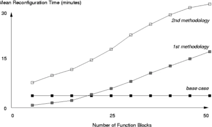
In an experiment, diversity is introduced into the decentralized manufacturing control system. A base case is established where a static assignment of capsules to controllers is made prior to the simulation. Against this base case, our two methodologies are to be critiqued. A pair of experiments has been conducted whereby select groups of capsules are introduced into the control system based on the application of the 1st and 2nd methodologies. We assume the simulation progresses in discrete intervals of a single minute. The graph of mean reconfiguration time for the three experiments is shown in Figure 9. This illustrates that, for the 1st methodology, the time to re-allocate capsules over controllers after a breakdown or sensor change decreases slightly as the number of affected capsules increases from zero to eighteen out of a total population of 50 capsules (i.e. function blocks). For 18 capsules based on applying the 1st methodology, the percentage decrease in mean reconfiguration time is 12.4% per capsule.
Figure 9: Evaluation of Performance Metric 1.
Yet, as the number of capsules increases beyond eighteen, the reconfiguration time increases and even exceeds the value corresponding to the base case (with its entirely rigid capsule to controller assignment regime). Thus with a few capsules that can be migrated, the mean reconfiguration time (after taking into account the associated overhead) is good. But as the number of large-grain capsules grows, the overall performance worsens. When the 2nd methodology is applied, there is a significantly higher proportion of time used to reconfigure the control system than is needed for the 1st methodology. After examining the experimental results we conclude there exists a ratio of 6.72 more time used to reconfigure the control using the 2nd methodology.
The underlying cause of this behavior can be explained as follows. When large-grain capsules have to be re-located, some decision has to be made to determine which controller to put the capsule on, and this decision must take into account the anticipated load and desired functionality of the controller (i.e. a sensor input function block cannot be run on a controller that does not have a suitable interface to the sensor on the shop-floor). When the control system has to re-assign approximately ten small-grain capsules (i.e. the nine capsules equivalent to
the single E_CTU function block) as part of the 2nd methodology then more decisions have to be made and different assignment combinations evaluated. This leads to a longer mean reconfiguration time than with the 1st methodology.
Note that there is a difference between the observed result of a 6.72 order of magnitude, rather than the ten as would be expected, since there are 10 times as many capsules resident using the 2nd methodology than with the 1st methodology. To account for this anomaly, we postulate that some capsules have a small footprint and require minimal load; thus making assignment of them to controllers a quick process with little need to rollback any re-allocations. Clearly, an excessive number of either large-grain (1st methodology) or small-grain (2nd methodology) capsules will create a scenario where load over the controllers is unequal and very few re-assignment options are available, thus leading to a breakdown in the normal reconfiguration process.
4.2 Distributing Capsules over Controllers
To verify the above hypothesis, Figure 10 presents the distribution of controllers that the large-grain capsules (1st methodology) and small-grain capsules (2nd methodology) can run on throughout the simulation’s progress. There are three plots – one denoting the base case where no reconfiguration is possible, the other two with re-assignment based on applying the two methodologies and using a simple first-come-first-served decision method.
Figure 10: Evaluation of Performance Metric 2.
For the base case population, the average number of controllers available (taken over the entire 50 capsules) was 11, while with our reconfiguration methodologies the average is much higher at 16 and 18 controllers. Additional analysis reveals that for the base case, after the first four controller breakdowns or function block changes, 27% of the capsules should have been re-assigned but all have failed as no reconfiguration is possible, and half of all the capsules would have to be migrated after 324 minutes. The corresponding numbers for the 1st methodology are 12% blocked (of the 27% that should be moved) and 189 minutes. While for the second methodology, they are 4% blocked and 103 minutes respectively. Clearly, having more flexibility with respect to where a capsule can reside
results in an increase in relative performance (1.71 for the 1st methodology and 3.14 for the 2nd methodology).
4.3 Controller Load
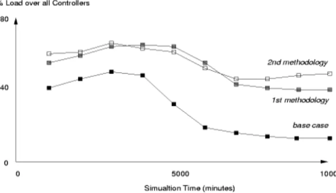
Figure 11 shows how the percentage load (averaged across all controllers) alters over time as reconfiguration occurs.
Figure 11: Evaluation of Performance Metric 3.
By design, capsules created with the 1st methodology have larger granularity and so when resident on the controller they have success in occupying a greater percentage of the controller’s potential load. Conceivably, this ability demands that the decentralized manufacturing control system must apply some special resources during its decision-making as part of the reconfiguration process. An experiment has been designed to evaluate the percentage load across the 20 controllers and the differential load used by capsules belonging to the 1st and 2nd methodologies. Analysis of the data obtained from this experiment, see Figure 11, reveals that the average load on controllers is similar for both methodologies for the initial 60% duration of the simulation with the 2nd methodology becoming better towards the end of the experiment. Also the difference between the average controller load based on either the 1st or 2nd methodologies and the base case increases with time (i.e. as more controller breakdowns and sensor changes happen). Clearly, the smaller granularity of the capsules created by the 2nd methodology mean that they could fill any spare capacity on the controllers. Meanwhile 1st methodology capsules fill a relatively larger proportion of a controller when they are assigned and so leave holes that are too small to accommodate an entire function block.
5 CONCLUDING COMMENTS
The paper has presented two orthogonal methodologies to mapping UML capsules to IEC 61499 function blocks. These entities are the fundamental building blocks of the next generation of decentralized manufacturing control systems that will allow manufacturing businesses to be more agile, i.e. produce goods in smaller batch sizes, deliver them to market quicker and make more efficient use of available resources. We have also evaluated our methodologies with respect to how responsive the system is to requests for reconfiguration.
REFERENCES
[1] M. Fletcher, R.W. Brennan and D.H. Norrie, Design of Real-Time Distributed Manufacturing Control Systems using UML Capsules, In the 7th International Conference on Object-Oriented Information Systems, published by
Springer, 2001.
[2] A. Koestler, The Ghost in the Machine (London: Arkana 1967).
[3] Overview of Holonic Manufacturing System Project, 2000, http://hms.ifw.uni-hannover.de/public/overview.html [4] X. Zhang, R. Brennan and D.H. Norrie, Conceptual Architecture for a Holonic Distributed Control System, technical report of University of Calgary, 2000.
[5] B.P. Douglass, Doing Hard Time: Developing
Real-Time Systems with UML, Objects, Patterns and Frameworks, (Addison-Wesley, 1999).
[6] B. Selic, G. Gullekson and P.T. Ward, Real-Time
Object-Oriented Modeling, (John Wiley and Sons, 1994).
[7] C. Wurll et al, A Distributed Planning and Control System for Industrial Robots, In the 5th International IEEE Workshop on Advanced Motion Control, 1998.
[8] B. Selic, Periodic Tasks in ROOM, In the ACM
Workshop on Real-time Object Oriented Systems, 1995.
[9] B. Selic, A Framework for Location Transparency in Distributed Systems, In the IEEE Workshop on
Object-oriented Real-time Dependable Systems, 1997.
[10] A. Lyons, Developing and Debugging Real-Time Software with ObjecTime Developer, Real-Time