Characterization and Mitigation of
Blade Waviness Effects on Fan Performance
by
Jinwook Lee
B.S., Seoul National University (2013)
S.M., Massachusetts Institute of Technology (2015) Submitted to the Department of Aeronautics and Astronautics
in partial fulfillment of the requirements for the degree of Doctor of Philosophy in Air-Breathing Propulsion
at the
MASSACHUSETTS INSTITUTE OF TECHNOLOGY September 2019
@Massachusetts
Institute of Technology 2019. All rights reserved.A uthor ... Certified by... Certified by... Certified by... Certified by...
Certified by ...
Si
Signature redacted
..
...
Department of Aeronautics and Astronautics
r'. t August 14, 2019
...
Signa ur re
(3Zoltin
S. SpakovAiky
Professor of Aeronautics and Astronautics , Thesis Supervisor
... Signature
redacted ...
Edward M. Greitzer H.N. Slgtr Professgx f Aeronautics and Astronautics
Signature redacted
Thesis Supervisor
...
Mark Drela Terry J. Kohler Professor
Signature redactedmtteeMember
...
...
..
Qiqi Wang
/A
~iate Professor of Aeronautics and Astronautics
Committee Member
gnature redacted,.
...
J. Nicholas A. Cumpsty
Emeritus Professor, Imperi l College London '[imittee Member
Accepted by
...
Signature redacted
MASSACUSTIT UM / Setc araman
Associate e rofAerc/autics andAstronautics Chair, Graduate Program Committee
Characterization and Mitigation of
Blade Waviness Effects on Fan Performance by
Jinwook Lee
Submitted to the Department of Aeronautics and Astronautics on August 14, 2019, in partial fulfillment of the
requirements for the degree of
Doctor of Philosophy in Air-Breathing Propulsion
Abstract
The role of surface waviness, arising from carbon composite manufacturing process, on aeroengine fan blade performance is characterized. The mechanisms for laminar-turbulent transition are assessed numerically and experimentally over relevant range of aerodynamic and geometric parameters. The governing mechanism (natural transition triggered by re-ceptivity amplification from surface waviness) is explained based on a newly established numerical framework and validated experimentally.
Computations and experiments are performed to assess the surface waviness loss mecha-nism under a relevant range of aerodynamic and geometric parameters. The major feature, with estimated isentropic efficiency loss up to 1%, is identified to be the movement of the natural transition location due to receptivity amplification, via geometric resonance between the Tollmien-Schlichting wavelength and the surface wavelength.
An effective numerical framework, referred to as the extended eN method, is estab-lished to assess the occurrence of the start of transition by tracing the energy transfer from freestream acoustic disturbance to initiation and growth of Tollmien-Schlichting waves. A subsonic natural transition wind tunnel was designed and constructed to determine the effects of surface waviness on natural transition. The theoretical amplification of Tollmien-Schlichting waves, and the corresponding transition point movement due to surface waviness, is successfully validated by these experiments.
The research contributes to aircraft engine fan blade technology through a new capability to estimate the effect of blade surface waviness on fan performance, characterization of the underlying mechanisms, and design guidelines for improvements of modern carbon composite fan blades.
Thesis Supervisor: Zoltdn S. Spakovszky
Title: Professor of Aeronautics and Astronautics
Thesis Supervisor: Edward M. Greitzer
Acknowledgments
First, I would like express my sincere gratitude to my advisors for their great insights and advice during my long journey at MIT GTL. I was particularly privileged to have had all three faculty members of Gas Turbine Lab as my advisors. I would like to thank Dr. Tan for giving me a wonderful opportunity to start my journey at MIT, which has been my dream ever since I was a child. I would like to appreciate Prof. Spakovszky and Prof. Greitzer for being my wonderfully supportive doctorate advisors. I am deeply grateful for their endless patience and encouragement even after the cascade of failures of experiments. Thanks to their consistent support and guidance, I completed my journey at MIT with results and contributions that I can be proud of.
Both the analytic and experimental aspect of the research have been substantively re-inforced by my thesis committee and thesis readers. I would like to specially thank Prof. Drela for enlightening me on the concept of receptivity, which essentially became one of the central themes of the research, and for sharing the detailed geometry of contraction and guide vanes for the test rig design. Also, I would like to appreciate the generous help and support from Prof. Cumpsty (Imperial College London) on my thesis and presentations. Lastly, I would like to thank Prof. Wang, Prof. Saric (Texax A&M University), and Prof. Uranga (University of Southern California) for sharing insightful and invaluable comments on my thesis.
The experimental work has made its way through a series of miracles, which was accom-plished thanks to countless help and support from many great people. First, I would like to deeply appreciate both financial and technical support from Safran Aircraft Engines. I would also like to thank Vaishnavi Ramaswami for her great help on fabricating the critical components for the experiment. I will not forget all the amazing technical support and fun experience with 4 MIT magicians who established the backbone of my experiment: James Letendre, Mark Belanger, David Robertson, and Todd Billings. I would like to thank Leonie Malzacher for helping me to collect the eleventh hour data points before the defense. Lastly, I really appreciate Robin Courchesne-Sato for tracing and organizing all the complicated purchase orders to so many different companies.
I appreciate all the great help and encouragement from all my GTL friends. I would like to specially thank Andras Kiss, In Young Hur, Yuankang Chen, Aniwat Tiralap, George
Christou, Lucie Reymondet and Albert Gnadt. Especially, I would like to thank Andras Kiss once again for his consistent support through, but not limited to: a lot of classes, qualifying exam, DeLaval experiments, and GTL cluster administration.
The help from my Korean friends at MIT will be remembered. I would like to express my special thank to Hyosang Yoon, In Young Hur and Sungkwon Hong for all the memorable times at MIT and keeping me encouraged. I would like to also thank Dong Ki Kim, HongSeok Cho, and Joseph Kim for their consistent support during the long journey at MIT AeroAstro. Lastly, I would like to thank Changhoon Oh and Woo Chang Chung for their help and support during my Master's.
Only after the 3rd year at MIT, I started to appreciate the joy of living in Boston. I would like to express my special thanks to Wui Yarn Daphne Chan for providing me the window through which I could see and explore the outside world beyond the lab and research. Finally and most importantly, I would like to express my deepest gratitude and ap-preciation for the endless support and love from my family: my mom, my dad, and my brother Sungwook. Without their love and support, none of my achievements could have been possible.
Contents
1 Introduction
1.1 Motivation: Surface Waviness and Surface Roughness . . . . 1.2 Problem Statem ent . . . . 1.3 Research Hypothesis . . . .. . . . . 1.4 Mechanism of Boundary Layer Receptivity . . . . 1.5 Literature Review . . . . 1.5.1 Roughness and Hydraulic Smoothness . . . . 1.5.2 Computational Approaches to Effects from Roughness . . . . 1.5.3 Computational Approaches to Effects from Surface Waviness . . . . . 1.5.4 Assessing Transition Point Movement Due to Surface Waviness . . . . 1.5.5 Modelling of Boundary Layer Receptivity . . . . 1.6 Research Questions . . . . 1.7 Research Objectives . . . . 1.8 Thesis Contributions . . . .
2 Technical Approach
2.1 Independent Control of Aerodynamic and Geometric Parameters 2.2 Experimental Approach . . . . 2.3 Numerical Approach . . . .
3 Relevant Non-Dimensional Parameters
3.1 Geometric Parameters . . . . 3.1.1 Surface Wave slope: Variation Scaling Parameter . . . . . 3.1.2 Surface Wavelength: Influence Range Parameter . . . . . 3.1.3 Geometric Regime Quadrants . . . .
39 . . . 39 . . . 41 . . . 42 45 . . . 45 . . . 46 . . . 49 . . . . 51 21 21 24 25 26 29 29 30 31 32 33 34 35 36
3.1.4 Limit of -y - Re6 Transition Model in Geometric Regime of Interest . . 3.1.5 Waviness Onset Location: Flow Perturbation Onset Location Parameter 3.2 Aerodynamic Parameters . . . .
3.2.1 Reynolds Number and Boundary Layer Shape Parameter . . . . 3.2.2 Mach Number and Compressibility . . . . 3.2.3 Pressure Gradient and Boundary Layer Instability . . . . 3.2.4 Aerodynamic Regime Quadrants . . . . 3.3 Range of Exploration for Each Parameter . . . . 3.4 Sum m ary . . . .
4 Development of Extended eN Method for Boundary Layer Transition with Surface Waviness
4.1 Motivation and Outline of Extended eN Method . . . . 4.1.1 Motivation of Extended eN Method . . . . 4.1.2 Outline of Extended eN Method . . . .
4.2 Distributed Receptivity and Weighted Sliding Window Method 4.2.1 Distributed Receptivity Modelling by Choudhari . . . . 4.2.2 Experimental Validation of Receptivity Model . . . . 4.2.3 Method of Weighted Sliding Window for Spatially Non-H
Surface . . . . 4.3 Linearized Navier-Stokes Equation . . . . 4.3.1 Motivation of Linearized Navier-Stokes Equation . . . . 4.3.2 Derivation of Linearized Navier-Stokes Equation . . . . 4.3.3 Utility of Linearized Navier-Stokes Equation . . . . 4.4 Local Stability and Orr-Sommerfeld Equation . . . . 4.4.1 Growth of Instabilities and eN Method . . . . 4.5 Simplified Transition Model in Extended eN Method . . . . 4.6 Assessment of Simplified Transition Model . . . . 4.6.1 Transition Onset Criterion . . . ..
. . . 61 . . . 63 . . . 63 . . . 63 omogeneous . . . 65 . . . 71 . . . 71 . . . 71 . . . 76 . . . 77 . . . . 78 . . . 80 . . . 82 . . . 82
4.6.2 Transition End Criterion and Scaling Factor for Transition Extent . . 85
4.6.3 Utility of Simplified Transition Model . . . . 86
4.7 Physical Interpretation of Transition in Extended eN Method . . . . 87 52 53 53 53 54 55 55 56 58 59 60 60
4.8 Empirical Parameters in Extended eN Method . . . 92
4.9 Sum m ary . . . . 93
5 Mechanisms of Transition Point Movement due to Surface Waviness 95 5.1 Local Stability Mechanisms . . . 95
5.1.1 Crests and troughs . . . 96
5.1.2 Local instability growth rate change due to surface waviness . . . 97
5.1.3 Stability asymmetry triggered by increasing non-dimensional wave height, ri/0 . . . 98
5.1.4 Stability symmetry recovered by increasing non-dimensional wave-length: A/0 . . . . . 99
5.1.5 Transition point movement due to boundary layer destabilization . . .100
5.2 Definition of Boundary Layer Edge Velocity Distribution . . . 101
5.2.1 Definition of Acoustic Disturbance and Surface Roughness . . . 102
5.3 Transition on Non-Wavy Reference Surface . . . 103
5.4 Transition Point Movement due to Boundary Layer Destabilization . . . 105
5.5 Transition Point Movement due to Receptivity Amplification . . . 107
5.6 Transition Point Movement due to Surface Waviness . . . 110
5.7 Sum m ary . . . 113
6 Experimental Assessment of Surface Waviness Effects on Natural Transi-tion 115 6.1 Outline of Experiment . . . . 6.1.1 Objective: Assessment of Transition Point Movement . . 6.1.2 Functional Requirements for Experiment . . . . 6.1.3 Tolerance Requirements for Experiment . . . . 6.1.4 Methods for Parameter Control and Measurements . . . 6.1.5 Experiment Test Matrix . . . . 6.2 Design and Construction of Test Rig . . . . 6.2.1 Design of Test Rig . . . . 6.2.2 Design of Test Plate . . . . 6.2.3 Capability of Constructed Test Rig . . . . 6.3 Test Section Flow Quality . . . . . . . 115 . . . 115 . . . 116 . . . 116 . . . 117 . . . 118 . . . 120 . . . 120 . . . 123 . . . 124 . . . 124
6.4 Limitations of Experimental Capability . . . . 6.5 Experimental Procedure . . . . 6.5.1 Signal Processing . . . . 6.6 Experimental Validation of Extended eN Method . . . . 6.6.1 Test Plate Surface Geometric Spectrum Characterization . . . . 6.6.2 Effect from 3D Flow Field on Pressure Distribution along Chord . . 6.6.3 Assessment of Extended eN Method and Sensitivity to Pressure Dis-tribution . . . . 6.7 Assessment of Research Hypothesis: Transition Point
Movement due to Receptivity Amplification . . . . 6.8 Effect of Wave Height and Waviness Onset Location . . . . 6.9 Effect of Crest Series vs. Trough Series . . . . 6.10 Sum m ary . . . . 125 126 126 127 127 .128 130 131 133 134 135
7 Design Guidelines for Fan Performance Improvement 137
7.1 Sensitivity of Isentropic Efficiency to Transition Point Location . . . 138
7.2 Estimation of Fan Performance Loss due to Surface W aviness . . . 141
7.2.1 Suggested Design Guidelines based on Geometric Parameters . . . 142
7.3 Fan Performance Improvement via Blade Profile Curvature Rescheduling . . . 144
7.3.1 Definition of Critical Receptivity Site . . . 144
7.3.2 Curvature Rescheduling . . . 145
7.3.3 Mechanism of Transition Delay via Curvature Rescheduling . . . 148
7.4 Sum m ary . . . 151
8 Summary of Contributions and Recommendation for Future Work 8.1 Summary of Contributions ... 8.2 Recommendation for Future Work ...
8.2.1 Compressibility Effects on Transition Point Movement ... 8.2.2 Three Dimensional Effect on Transition Point Movement . . . .
A Utility of Linearized Navier-Stokes Equation
A.1 Utility and Adequacy of Linearized Navier-Stokes Equation . . . . 153 153 156 156 157 159 159
A.1.1 Incompressible Inviscid Flow . . . 161
A.1.2 Incompressible Viscous Flow . . . 163
A.1.3 Laminar Boundary Layer . . . 164
A.1.4 Turbulent Boundary Layer . . . 165
A.2 Utility Limits of Linearized Navier-Stokes Equation (LNS) . . . 166
A.2.1 Non-linear Flow Variations from High Slope Surface Waviness: r/A ~ 0.1 ... 166
A.2.2 Compressibility Effect in Flow Variations: Mach Number - 1 . . . 167
B Utility of Simplified Transition Model 169 C Additional Computational Results for Chapter 5 171 D Experiment Setup Design Details 175 D.1 Freestream Turbulence Mitigation . . . 175
D.2 Acoustic Noise Mitigation . . . 176
D.3 Structural Vibration Mitigation . . . .. 177
D.4 Air Leakage Prevention . . . 178
D.5 Materials and Fabrication . . . 178
D.6 Test Rig Assembly Procedure . . . 180
E Experiment Procedure 187 E.1 Room Condition Characterization . . . 187
E.2 Sensor Calibration . . . 189
E.3 Mitigation of CTA Bridge Circuit Resonance Effects on Hotwire Measurements190 E.4 Establishment of Experimental Condition . . . 191
E.5 Boundary Layer Traversing . . . 193
E.6 Experiment Procedure Details . . . 195
F Additional Measurement Results 197 F.1 Upstream Influence from Microphone . . . 198
F.1.1 Signal Processing . . . .. 199
G Square Wave Train Surrogate Tests G.1 Introduction . . . . G.2 Formation of Square Wave Pattern G.3 Validity of Square Wave Train Tests
G.3.1 2D Laminar Computation . G.3.2 Stability Analysis . . . . G.3.3 Receptivity Analysis...
H Stagnation Pressure Loss due to Boundary Layer Dissipation
H.1 Sensitivity of Stagnation Pressure Loss to Transition Point Location . . . .
I Estimation of Fan Performance Loss due to Surface Waviness
207 .207 .207 .208 .208 .213 .214 217 .218 223
J Compressibility Effect on Transition Point Movement due to Surface
Wavi-ness 229
J.1 Compressibility Effect on Boundary Layer Stability and Transition . . . 229 .J.2 Scaling Law for Mach Number Effect on Transition . . . 231 J.3 Sum m ary . . . 234 ... ... ... ... ... ...
List of Figures
1-1 Measured Waviness and Roughness on carbon composite fan blade 1-2 Measured Waviness and Roughness Slope
Research Hypothesis . . . . Turbulence Intensity and Transition Location . . Acoustic Receptivity Mechanism . . . . A High Fidelity Mesh Resolving the Actual Surfac
. . . 2 3
e Wa 1-7 Shockwave Induced Separation Loss Mechanisms
Schematic of Diffusing Passage Experiment . . . . Grid Independence Test Result . . . . MISES For Tunnel Top Wall Shaping . . . .
Definition of Surface Waviness . . . . Flow Variations on an Infinite Periodic Wavy Surface . Loss Rate Change for Various Wavy Cases . . . . Grid Independence Test Result . . . . Two Limiting Cases of Range of Influence . . . . The Change of Loss Rate Along Chord . . . . Geometric Regime Quadrants . . . . Limit of ' - Reo Transition Model . . . . Distribution of Mach Number Variation . . . . Flow Regime Quadrants . . . . Isentropic Mach Number Distribution . . . .
. . . . 2 5 . . . . 2 6 . . . 2 7 viness . . . 30 . . . 3 1 . . . 4 0 . . . 4 2 . . . 4 3 . . . 4 5 . . . 4 6 . . . 4 7 . . . I. . . . 48 . . . 4 9 . . . 5 0 . . . 5 1 . . . 5 2 . . . 5 4 . . . . 5 5 . . . . 5 7
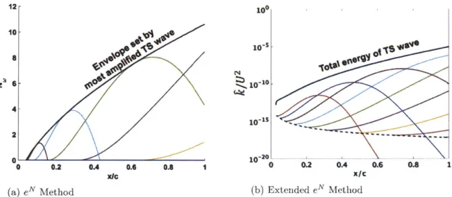
4-1 Receptivity to Natural Transition . . . . 4-2 Comparison of eN Method and Extended eN Method . . . . 1-3 1-4 1-5 1-6 2-1 2-2 2-3 3-1 3-2 3-3 3-4 3-5 3-6 3-7 3-8 3-9 3-10 3-11 61 . . 62 23
5-6 5-7 5-8 5-9
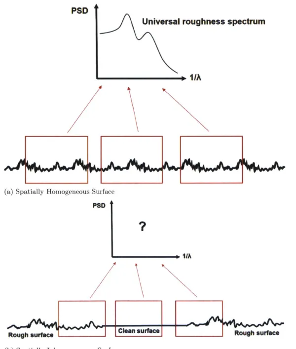
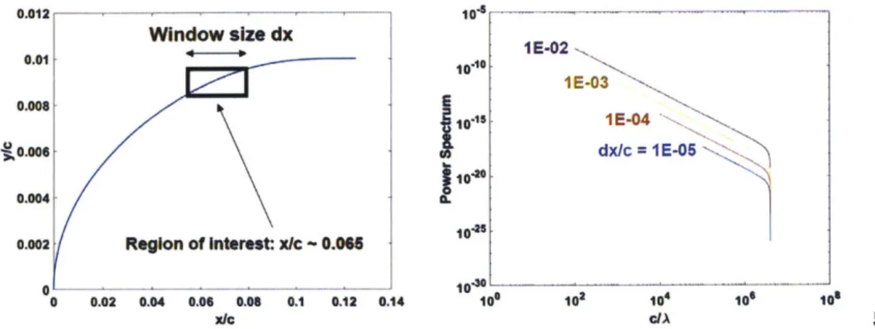
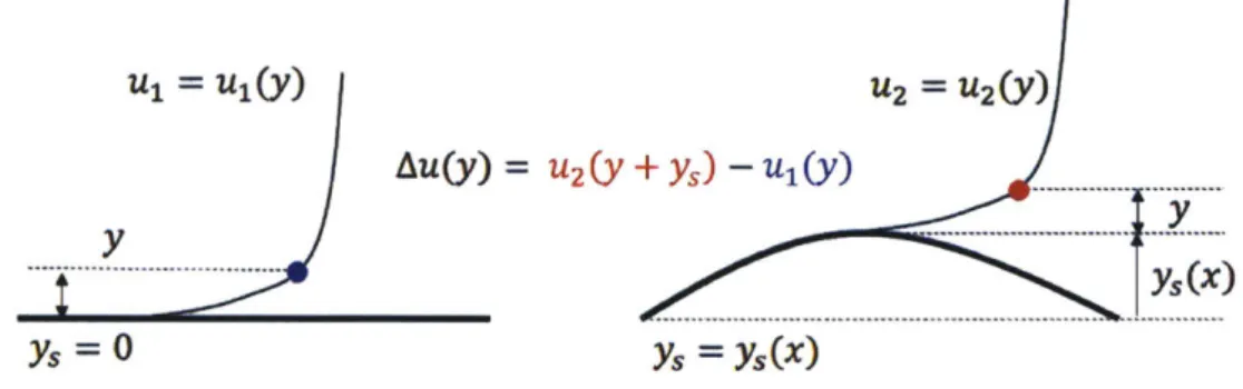
4-3 Experimental Validation of Receptivity Modeling . . . . 4-4 Spatial Homogeneity of Surface Spectrum . . . . 4-5 Arbitrariness Issue on Window Size for Spectral Analysis . . . . 4-6 Receptivity Coordinate Set by Tollmien-Schlichting Wavelength 4-7 Receptivity Affected by Upstream Geometry . . . . 4-8 Receptivity Affected by Downstream Geometry . . . . 4-9 Weight Distribution for Weighted Sliding Window . . . . 4-10 Concept of Weighted Sliding Window . . . . 4-11 Wall Corrected Variations . . . . 4-12 Wall Corrected Coordinate Transformation . . . . 4-13 Assessment of LNS against Laminar CFD . . . . 4-14 Eigenmode Structure . . . . 4-15 Assessment of eN Method . . . . 4-16 Simplified Transition Model . . . . 4-17 Evolution of Disturbance Power Spectrum . . . . 4-18 Transition Onset Criterion on Wavy Plate . . . . 4-19 Measured Extent of Transition Process . . . . 4-20 Transition Model for Various Wavy Cases . . . . 4-21 Exponential Growth of Tollmien-Schlichting Wave . . . . 4-22 Computed Profile of Tollmien-Schlichting Wave . . . . 4-23 Transition Onset Location . . . . 4-24 Transition Process in Extended eN Method . . . .
5-1 Effect of a Crest on Boundary Layer Stability . . . . 5-2 Variation of Local Stability from Crests and Troughs . . . . 5-3 Scale of Local.Stability Change due to Surface Waviness . . . . 5-4 Destabilizing Effect of 7/0 on Local Stability . . . . 5-5 Stabilizing Effect of A/0 on Local Stability . . . .
Transition Point Movement for Different Wave Heights and Wavelengths . . . 100
Canonical Boundary Layer Edge Velocity Distribution . . . 101
White-Pink Noise Spectrum Used as Inputs to Extended eN Method . . . 102
Effect of Shape Parameter on Tollmien-Schlichting Wave Growth . . . 103
. . . 64 . . . 65 . . . 66 . . . 67 . . . 68 . . . . 68 . . . 69 . . . 70 . . . 71 . . . 72 . . . 76 . . . 78 . . . 79 . . . 81 . . . . 82 . . . . 84 . . . 85 . . . 86 . . . 88 . . . 89 . . . 90 . . . 91 . . . . . 96 . . . 96 . . . 97 . . . 98 . . . 99
5-10 Growth of Tollmien-Schlichting Wave on Non-Wavy Surface . . . . 5-11 Effect from Geometric Parameters on Tollmien-Schlichting Wave Growth . . 5-12 Effect from Boundary Layer Destabilization on Transition Point Movement 5-13 Effect of Geometric Parameters on Receptivity Amplification . . . . 5-14 Effect from Geometric Parameters on Receptivity Amplification . . . . 5-15 Effect from Receptivity Amplification on Transition Point Movement . . . . 5-16 Surface Waviness Effects on Transition Point Movement for Various Wave Heights and Reynolds Numbers . . . . 5-17 Surface Waviness Effects on Transition Point Movement for Various Aerody-nam ic Param eters . . . . 5-18 Surface Waviness Effects on Transition Point Movement for Various Waviness
Onset Locations . . . .
Definition of Surface Waviness . . . . Test Rig Design Overview . . . . Test Plate Design . . . . Measured Test Section Freestream Turbulence Level . . . Test Section Acoustic Noise Level . . . . Boundary Layer Disturbance Noise Filtering . . . . Measured Surface Geometric Spectrum . . . . Assumed Pressure Distribution . . . . Sensitivity of Extended eN Method to Pressure Gradients 6-10 Tollmien-Schlichting Wave Amplification . . . .
Transition Point Movement for Various Aerodynamic Paramete Tollmien-Schlichting Wave Amplification . . . . Topography of Wavy Pattern . . . .
. . . 112 . . . 119 . . . 121 . . . 123 . . . 124 . . . 125 . . . 126 . . . 127 . . . 129 . . . 130 . . . 131 rs . . . 132 . . . 133 . . . 134
Representative Suction Surface Isentropic Mach Number Distributions . . . .140
Estimated Fan Performance Loss due to Surface Waviness . . . 141
Wave Height Effect on Transition . . . 142
Waviness Onset Location Effect on Transition . . . 143
Receptivity Site . . . 144
Critical Receptivity Site . . . 145 .104 .105 .106 .107 .108 .109 .110 . 111 6-1 6-2 6-3 6-4 6-5 6-6 6-7 6-8 6-9 6-11 6-12 6-13 7-1 7-2 7-3 7-4 7-5 7-6
7-7 Curvature Rescheduling of Test Plate . . . 146
7-8 Transition Delay Using Curvature Rescheduled Test Plate . . . 147
7-9 Definition of Test Plate Profile Geometry with Various Leading Edge Lengths 148 7-10 Pressure Distribution for Various Leading Edge Lengths . . . 149
7-11 Transition on Various Leading Edge Lengths . . . 150
A-1 Level of Complexities for Assessment of LNS . . . 160
A-2 Assessment of LNS against Analytic Solution for Incompressible Inviscid Flow 162 A-3 Pressure and Skin Friction Along the Wall . . . 163
A-4 Assessment of LNS against Laminar CFD . . . 164
A-5 Assessment of LNS against Turbulent CFD . . . 165
A-6 Pressure Distribution along and away from the Wall . . . 167
A-7 Effect of Mach Number . . . 168
B-1 Assessment of Transition Model for Non-Wavy Cases . . . 169
B-2 Assessment of Transition Model for Wavy Cases . . . 170
C-1 Canonical Boundary Layer Edge Velocity Distribution . . . 171
C-2 Effect from Boundary Layer Destabilization on Transition Point Movement . 172 C-3 Effect from Receptivity Amplification on Transition Point Movement . . . 173
C-4 Surface Waviness Effects on Transition Point Movement for Various Govern-ing Param eters . . . 174
D-1 Contraction Area Scheduling - Designed by Prof. Mark Drela. . . . 176
D-2 Turning Guide Vanes - Designed by Prof. Mark Drela. . . . 176
D-3 Diffuser Insert Diameter Distribution -Each symbol indicates different stage. Rectangle section is based on hydraulic diameter. . . . 177
D-4 Test Rig Design - Overview . . . 182
D-5 Test Rig Design - Inside . . . 183
D-6 Constructed Test Rig . . . 184
D-7 Probes Mounted on Traverse Arm . . . 185
D-8 Upstream Influence from Microphone . . . 185
E-2 E-3 E-4 E-5 F-1 F-2 F-3 F-4 F-5 F-6 F-7
Top Wall Profile ... Monitoring of Experimental Condition . . . . Boundary Layer Traversing . . . . Measured Boundary Layer Profile . . . .
Upstream Influence from Microphone . . . . Boundary Layer Disturbance Noise Filtering . . . . Assessment of Extended eN Method against Measurements Tollmien-Schlichting Wave Amplification . . . . Tollmien-Schlichting Wave Amplification . . . . Tollmien-Schlichting Wave Amplification . . . . Tollmien-Schlichting Wave Amplification . . . .
F-8 Transition Point Movement for Various Aerodynamic and Geometric Parameters205
G-1 Polymide Tape Square Wave Train . . . 208
G-2 Square Wave Pattern Mesh . . . 209
G-3 Chordwise Flow Perturbation . . . 210
G-4 Square Wave Height . . . 210
G-5 Comparison of 2D Flow Perturbation due to Sinusoidal Wave Pattern and Square W ave Pattern . . . 211
G-6 Comparison of Boundary Layer Profile Perturbation due to Sinusoidal and Square W ave Patterns . . . 212
G-7 Stability Change due to Surface Wave Patterns . . . 213
G-8 Surface Spectrum from Various Surface Patterns . . . 214
G-9 Effect of Surface Wave Pattern on Transition . . . 215
H-1 Stagnation Pressure Loss and Transition Location . . H-2 Corrected Stagnation Pressure Loss . . . . I-1 1-2 1-3 1-4 Wave Height Effect on Fan Performance . . . . Waviness Onset Location Effect on Fan Performance Wave Height Effect on Fan Performance . . . . Waviness Onset Location Effect on Fan Performance . . . 219 . . . 220 224 225 226 227 . . . 191 . . . 192 . . . 193 . . . 194 . . . 198 . . . 199 . . . 200 . . . 201 . . . 202 . . . 203 . . . 204
J-1 Growth Rate for Various Mach Number . . . 230 J-2 Velocity Thickness Corrected Boundary Layer Stability . . . 232 J-3 Sensitivity of Surface Irregularity on Transition Reynolds Number . . . 233
Nomenclature
a Spatial eigenvalue for boundary layer instability
A# The variation of a flow variable
#
due to surface waviness S Boundary layer thickness6*
Boundary layer displacement thickness6
e Boundary layer edge thickness
SEntropy generation rate
rSurface wave height, Isentropic Efficiency
q$Perturbation mode of flow varible#
A Heat conduction coefficient A Surface wavelength
p Dynamic viscosity
w Compressor/Fan blade loss coefficient
w Temporal eigenvalue for boundary layer instability
p Density
0
Boundary layer momentum thicknessc Chord length
c, Specific heat at constant pressure H Boundary layer shape parameter, 6*/
ht Stagnation enthalpy k Surface wave number,2
k, Equavalent sand grain diameter
M Mach number
m Waviness corrected transformed coordinate along horizontal direction n Waviness corrected transformed coordinate along vertical direction
p Pressure
PR Pressure ratio Pr Prandtl Number
Prt Turbulent Prandtl number
R Ideal gas constant
Ra Centerline averaged roughness height Rz Groove height
Re Reynolds number T Temperature
U Characteristic velocity scale
u Cartesian velocity component in x-direction
v Cartesian velocity component in y-direction
w Cartesian velocity component in z-direction
x Cartesian coordinate along chordwise direction y Cartesian coordinate along wall normal direction z Cartesian coordinate along spanwise direction
Chapter 1
Introduction
1.1
Motivation: Surface Waviness and Surface Roughness
Surface waviness on carbon composite aeroengine fan blades arises from the manufacturing process. The estimated fan performance loss due to surface waviness can be up to 1% in isentropic efficiency (Chapter 7). Loss scaling is important for fan manufacturers who seek balance between additional cost from tighter tolerance and an opportunity to achieve an enhanced performance, but scaling laws between surface waviness and fan performance are not well defined in the literature.
Surface waviness has been less studied than surface roughness which is of different scale
in length. Surface roughness results not only from the manufacturing process but also from degradation in surface finish with service, especially near the leading edge, as discussed by Bons [9]. The role of surface roughness is mainly confined to turbulence production in the boundary layer and transition point movement (Bons [9]) while the effect from waviness can also form shock waves in the potential flow adjacent to the blade as shown by Winter et al. [75]. Both surface waviness and roughness are small scale compared to the blade chord length scale irregularities on the designed surface geometry with the degree and the region of the flow variations depending on the length scale of the irregularity.
Recent work has successfully captured the effect of roughness using RANS (Reynolds Averaged Navier-Stokes Equation) for ([71], [79], and [10]) and showed that it is not required to use higher fidelity approaches such as LES (Large Eddy Simulation) and DNS (Direct Numerical Simulation) or the adjustment of turbulence closure in RANS (as in Yamamoto et
al. [78] or Fuhrman et al. [27]) in accounting for the roughness effect1. Surface roughness can be approximated as a short wavelength limit (compared to wave height) of surface waviness, which is consistent with a recent observation by Goodhand et al. [33] that the slope of the roughness is one of the governing geometric parameters on boundary layer perturbation.
Figure 1-1 shows measured surface waviness and roughness on carbon composite fan blade (data provided by industry). There is no generally agreed upon length scale criterion to define waviness versus roughness. Non-dimensional length scale criteria could span: sur-face wave height to viscous length scale2 ratio, surface wavelength to viscous length scale ratio, surface wave height to surface wavelength ratio. Among the list, the ratio of sur-face wave height height to sursur-face wave length (sursur-face wave slope) is suggested to be the appropriate criterion as the surface wave slope determines the scale of boundary layer per-turbation. Dimensional analysis in Chapter 3 shows that the local flow variations due to surface waviness are linearly proportional to surface wave slope if the slope is less than 0.1. A surface wave slope of 0.1 is thus suggested as a criterion between roughness and waviness (see Figure 3-7). The scale of measured surface wave slope in Figure 1-2 shows that the suggested criterion is appropriate. The surface roughness slope is on the order of 0.1 while the surface waviness slope is much less than 0.1.
There is large difference in the amount of work devoted to waviness compared to that of roughness, and the quantitative link between waviness and fan performance is not clear. The problem statement for the thesis, therefore, is given in the next section.
'The validity of RANS depends on the length scale of surface irregularity. For large scale (compared to viscous sublayer thickness) roughness (or obstacle) effect, RANS starts to deviate from other higher fidelity approaches (e.g. LES) in resolving the flow behavior after the obstacle. The deviation occurs due to large turbulent length scale behind the obstacle which is beyond the capability of RANS as discussed by Xie and Castro [77].
2
Viscous length scale is defined as 1, = v/u, where friction velocity is defined as Ur = Tp. v, r, P
5
10
0 5 10 15 20 25 30
x Imm) (a) Measured Surface Waviness
Figure 1-1: Measured Waviness and
U.a 0.6 0.4 0.2 0 -0.2 -0.4 -0.6 -0.8 0 1 2 3 4 5 x Imm)
(b) Measured Surface Roughness
Roughness on carbon composite fan Ilade
*x103 0.3 0.2 4 0.2 -2 0.1 00 -02 .0.1 -6 -0.2 •8 -0.3 0 5 10 15 20 25 30 0 1 2 3 4 5 x [mm) x
(mm)
(a) Measured Surface Waviness Slope (b) Measured Surface Roughness Slope
Figure 1-2: Measured Waviness and Roughness Slope - Surface wave slope of 0.1 is an appropriate criterion between waviness and roughness.
1.2
Problem Statement
Fan blade surface waviness arises from carbon composite manufacturing process for weight reduction in modern civil aircraft turbofan engines. Extensive use of carbon composite for fan blades, however, has been limited by unknown mechanisms of surface waviness effects on fan performance. The role of blade surface waviness on fan performance and the underlying mechanisms, therefore, need to be identified and characterized.
In this research, the effects of surface waviness on laminar-turbulent transition are as-sessed numerically and experimentally over a range of aerodynamic and geometric param-eters relevant to fan blade surface waviness. The governing mechanism (natural transition triggered by receptivity amplification from surface waviness) is explained based on a newly established numerical framework and validated experimentally.
The research will add value through characterization of parametric behavior and defi-nition of surface manufacturing requirements for improved performance. The payoffs are a new capability and a fundamental description of the mechanisms and related parameters underlying the effects of surface waviness on fan performance.
1.3
Research Hypothesis
It is hypothesized that surface waviness affects fan performance through movement of the natural transition point3, governed by receptivity4 amplification via geometric resonance between surface wavelength and Tollmien-Schlichting wavelength (see Figure 1-3). The dimensional analysis in Chapter 3 also suggests that a significant effect of compressibility due to surface waviness is not expected in the aerodynamic and geometric regimes of interest.
BL1 edge
Laminar Turbulent
'I Non.-wavySurface
Initial TS wave
Amplified receptivity from transition
geometric resonance movem
uedge r
Wavy 3urface
point ent
Figure 1-3: Research Hypothesis - Performance change from surface waviness arises from natural transition triggered by geometric resonance between Tollmien-Schlichting wavelength and surface wavelength. A longer turbulent section results in more loss.
3
Natural transition is a gradual process with a series of flow structures triggered by Tollmien-Schlichting wave in the upstream. The transition process is discussed in Chapter 4.
4Receptivity is an energy transfer process from external disturbances in freestream to an initial amplitude of boundary layer instability.
1.4
Mechanism of Boundary Layer Receptivity
Natural transition is a gradual flow process caused by infinitesimal disturbances in the boundary layer. The disturbances change sequentially from Tollmien-Schlichting waves to three-dimensional waves, to evolution and breakdown of 3D vortical structure, to formation of turbulent spots, and to fully turbulent flow, White
[73].
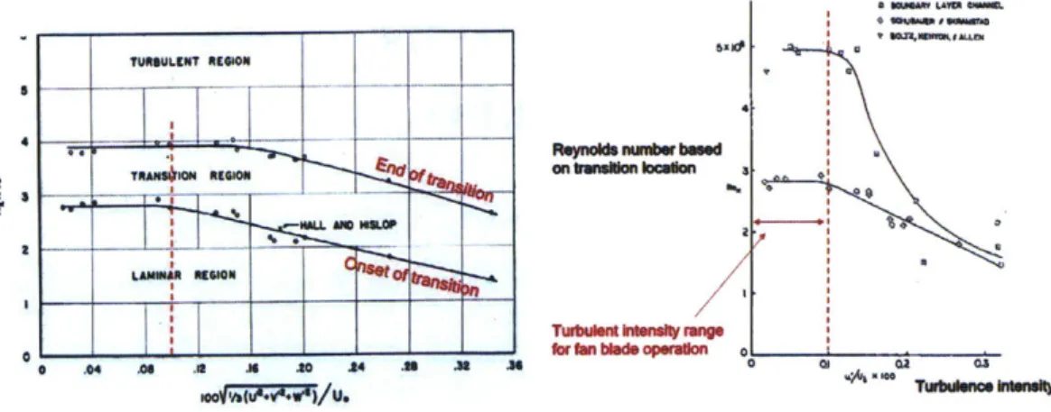
Stability analysis of Tollmien-Schlichting wave characteristics is necessary but not sufficient to characterize natural tran-sition because the initial amplitude of Tollmien-Schlichting waves is not accounted for. The initial amplitude of instability is set by boundary layer receptivity5 which is an energy trans-fer process from external disturbances in the freestream to an initial amplitude of boundary layer instability as discussed by Saric et al. [59].Receptivity can be categorized as vortical or acoustic depending on the type of external disturbances as suggested by Saric et al. [59]. For fan blades at cruise where freestream turbulence intensity is much less than 0.1%, there is little effect from vortical receptivity on transition (Figure 1-4) and acoustic receptivity governs the initial amplitude of boundary layer disturbances. I MLAVU4 * OWG #*ojw n" TURMLENT 4E410N anullnbednsn~n ren, ftlaf I I aL 0 LAMIIR 090 o ra cuna perae
(a) Figure Adapted from Schubauer et al. [61] (b) Figure Adapted from Wells [72]
Figure 1-4: Turbulence Intensity and Transition Location - A further reduction of freestream turbulence intensity below 0.1% does not affect transition indicating
desensitized effect from vortical receptivity on transition compared to acoustic receptivity effect.
5
A length scale conversion is critical for acoustic receptivity due to the factors of ten or more length scale mismatch between acoustic and Tollmien-Schlichting waves. The required length scale conversion is achieved via spatial non-uniformity of the boundary layer. Figure 1-5 shows the length scale conversion process through a kink. Depending on the type of wavelength conversion mechanism, receptivity is categorized as leading edge receptivity, localized6 receptivity, and non-localized 7
receptivity, Crouch
[18].
a
sound wave's oscillating pressure gradient
TS wave
weak strong weak
response response response (inflected profile)
Figure 1-5: Acoustic Receptivity Mechanism - The length scale conversion required for energy transfer from acoustic wave disturbances to boundary layer instability is achieved via spatial irregularity along boundary layer. Figure adapted from Drela [21].
6
Localized source of surface irregularity, e.g. curvature jump or hump
7
Acoustic receptivity is a quadratic effect of wall perturbation and acoustic forcing. For a boundary layer under wall perturbation y= % Sexp[-iawx] and acoustic forcing uac =
EacU, exp[-iwct] where perturbations are small (Ew, eac« Rex21/8 ~ 0.1 as discussed by Choudhari [14]), the velocity distribution can be expanded as follows.
U(,w, Eac; x, y, t/Um
= uo+ewnwexp[-iawx]+Eaciacexp[-iwt]+weacfrecexp[-i(awx+wct)]+-.-. (1.1)
In Eqn. 1.1, the first three terms correspond to the reference boundary layer, steady wall perturbation and Stokes wave respectively. The fourth term, which is the first term associated with both wall perturbation and acoustic forcing, defines the initial amplitude of Tollmien-Schlichting wave with wavelength of 27r/ae and frequency of wac. Various acous-tic receptivity theories have been proposed to compute the receptivity coupling coefficient
1.5
Literature Review
1.5.1 Roughness and Hydraulic Smoothness
The present research is focused on effects from surface waviness, not roughness. It is thus important to define a hydraulically smooth surface and criteria for hydraulic smoothness (criteria for surface irregularity height below which the skin friction is not affected) are discussed below.
A criterion is based on comparison of the sand grain diameter (k,) and viscous length scale, Nikuradse [55]. Experiments showed that roughness would not affect the skin friction if
k_ = Urk" < 5. (1.2)
5 V
For this roughness height, the boundary layer perturbation from the roughness is submerged in the wall layer and the surface can be considered hydraulically smooth.
Another criterion, based on sand grain diameter (k,) and chord length Reynolds number and using the data from Nikuradse [55], is suggested by Schlichting [60] as
ks,admin 100 (1.3)
c Rec
The centerline averaged roughness height (Ra) based approach combined with Eqn. 1.2 and Eqn. 1.3 can provide a useful framework to estimate the requirement for geometric tolerance distribution in gas turbine, Goodhand
[32].
Readers interested in discussion of other hydraulic smoothness criteria can refer to Bons [91 and Goodhand et al. [33].1.5.2 Computational Approaches to Effects from Roughness
One computational approach to roughness is to adjust turbulence models to account for roughness effects (Yamamoto [78], Fuhrman et al.
[27]).
The approach is consistent with the observation by Nikuradse [55] that the log-law near the wall is valid for the case of roughness with adjustments on the log-law parameters.In recent approaches ([71], [79], [10]) the RANS formulation has been successfully ap-plied without modifying turbulence models by resolving the actual surface geometry with a high fidelity mesh8 (Figure 1-6). RANS fails to capture turbulent structures and higher fidelity schemes become required (e.g. LES) as the size of surface irregularity becomes bigger (y+ > 500) as suggested by Xie and Castro
[77].
In this research, only small (y+ ~ 10) surface irregularities are concerned and RANS is directly used with resolved surface waviness geometries.177V1
.... ~ -.~.-..-t4
i
VT.,..-" ,. t ~(a) Isometry View of a High Fidelity Mesh (b) Top View of a High Fidelity Mesh
Figure 16: A High Fidelity Mesh Resolving the Actual Surface Waviness -Adaptive Cartesian grids are used to resolve the actual surface geometry. Figures adapted from Bons et al. [101.
8
1.5.3 Computational Approaches to Effects from Surface Waviness A linear analysis can be applied to assess surface waviness effects on the boundary layer as discussed by Benjamin [5]. Assessment of the linear analysis against DNS (Direct Numerical Simulation) by Esquivelzeta-Rabell et al. [25] suggests the linear analysis is appropriate when the surface wave slope is less than - 0.1.
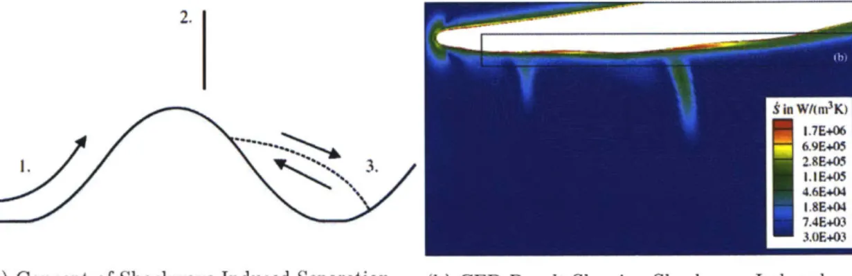
Outside the linear regime, surface waviness can create a non-linear flow structure such as a separation bubble on the leeward side of the wave or a shock wave near the crest of the wave. The shock wave induced separation bubble, especially, can be a loss mechanism associated with surface waviness (Figure 1-7) as discussed by Winter et al. [75]. In the geometric and aerodynamic regimes of present research, however, the shock wave induced separation mechanism is not applicable because the flow perturbation is submerged in the boundary layer. 2. 5 in W/(m3K) 1.7E+06 ---. 6.9E+05 3. 2.&E405 1. 1E+05 4.6E+04 1.8E+04 7.4E+03 3.3E+03
(a) Concept of Shockwave Induced Separation (b) CFD Result Showing Shockwave Induced
Loss Separation Loss (Red Colored Zones)
Figure 1-7: Shockwave Induced Separation Loss Mechanism - The acceleration of
flow (1.) near a crest can form a shock wave (2.). The jump in static pressure can induce a separation bubble (3.) loss associated with the surface waviness. Figures adapted from
1.5.4 Assessing Transition Point Movement Due to Surface Waviness For assessing natural transition (among the three categories of transition: natural transition, bypass transition, and forced transition)9, two methods can be considered based on compar-ison between physical fidelity and computational cost. DNS (Direct Numerical Simulation) captures all turbulent structures. The y - Reo method10 is a correlation for capturing in-termittency and turbulence kinetic energy as discussed by Menter et al. [52]. It has been successful in capturing the transition point in various flow conditions ([64], [45], [41]), but there is no guarantee that -y- Reo would be appropriate for a non-calibrated flow regimell and in fact the correlation does not hold for the range of geometric parameters for fan blade surface waviness (Figure 3-8).
The eN method (van Ingen [69], [70]) lies between between DNS andy- Reo in terms of physical fidelity and computational cost. The idea is to trace the exponential growth of the instabilities in a 2D boundary layer to assess the transition process, so the method can only capture natural transition mechanisms (Theofilis [66], [67]). A complete review of the
eN method is described by Reed [58].
The eN method relies on hydrodynamic stability analyses based on the Orr-Sommerfeld equation. The Orr-Sommerfeld equation is an ordinary linear differential equation from which the eigenmodes with associated temporal and spatial eigenvalues can be computed. A method suggested by Orszag [56] is used to solve the Orr-Sommerfeld equation in the present research.
In the eN method, the unstable spatial eigenvalues of the Tollmien-Schlichting wave2 are integrated to obtain an instability growth curve. The transition point is assumed to be where the wave grows beyond a empirical criterion, eNcrit. The framework of the eN method has been successful in various natural transition scenarios ([64], [49], [8], [69], [70]). Especially, transition point movement due to boundary layer destabilization from airfoil surface waviness was captured using the eN method by Boermans and Blom [8] although the effect from receptivity amplification was not considered.
Effect of non-parallel flow on boundary layer stability can be accounted for by using
9
See Kachanov [37] and Brandt et al. [111] for categorization of transition.
l0The name of the method comes from two governing parameters of the model: turbulence intermittency
y and momentum thickness based Reynolds number Reo. See Menter et al. [52] and Langtry et al. [41] for
more details.
"See Malan et al. [48] for additional calibration work on the correlation constants for -y - Reo method.
PSE (Parabolic Stability Equation) where the parallel boundary layer assumption in Orr-Sommerfeld Equation is not invoked (see [35], [66], [28], and [67] for reviews and applications of PSE). Bertolotti et al. [7], however, showed that the non-parallel flow effect on boundary layer stability is not critical for a incompressible boundary layer on a flat plate by comparing results from Direct Numerical Simulation, Parabolic Stability Equation, and Orr-Sommerfeld Equation. In this research, therefore, eN method is extended using the Orr-Sommerfeld equation.
1.5.5 Modelling of Boundary Layer Receptivity
Acoustic receptivity in natural transition has been successfully characterized in the past few decades although challenges remain for receptivity in bypass transition and vortical recep-tivity, Saric et al. [59]. Two different approaches have been applied in acoustic receptivity theories.
The first approach is based on matched asymptotic expansions of the velocity (Goldstein [30], [31]). The boundary layer is first categorized into triple-deck structure (Stokes layer, main inviscid region, outer inviscid region). Two flow regions (unsteady boundary layer region, Orr-Sommerfeld region) are then asymptotically matched to compute the receptivity coefficient. The theory successfully characterized receptivity due to the curvature
jump
at the leading edge-flat junction (Goldstein [30], [31]). The theory can also be extended to compressible flow as discussed by Bernots [6].The second approach is to solve the inhomogeneous Orr-Sommerfeld equation under acoustic forcing which then becomes a boundary value problem rather than an of eigenvalue problem ([17], [18], [15]). The approach by Choudhari [15] which uses this method is adopted for the extended eN method in Chapter 4. The theory has been successfully validated against experiments based on a Blasius boundary layer, performed by King [39].
1.6
Research Questions
The research questions are as follows.
1. What are the primary geometric variables that create the efficiency decrease with a
wavy wall relative to a non-wavy wall?
2. Under what conditions is the effect of waviness most marked? Are there parameter
regimes for which the flow is less sensitive to waviness?
3. What are the Mach number and the boundary layer Reynolds number regimes of greatest
sensitivity?
4. What are the effects of non-dimensional streamwise pressure gradient and overall pres-sure rise?
5. What are the effects of the leading edge boundary layer shape parameters?
6. Is the mechanism primarily two-dimensional in nature, or are there strong
1.7
Research Objectives
The research objectives are:
1. Characterize and quantify the aerodynamic regimes and geometric conditions under
which surface waviness is most detrimental to compressor performance
2. Determine the relevant mechanisms such that we are able to define how the results scale over these regimes and conditions
3. Define the opportunities for increases in performance
4.
Determine the degree to which one needs to mitigate the waviness to achieve these increasesThe research will identify the underlying mechanisms in terms of relevant parameters and sensitivity, and provide design guidelines for innovative compressor blade profiles robust to surface waviness.
1.8
Thesis Contributions
1. Identification of relevant geometric parameters (Chapter 3)
Most work on skin-friction has been focused on surface roughness height compared to viscous length scale to identify the hydraulic smoothness criterion (Bons [9]). In the present research, it is suggested that the surface wave slope sets scaling factor for flow variations and surface wavelength/boundary layer thickness characterizes a non-dimensional range of influence. Geometric Regime Quadrants are thus defined based on surface wave slope and wavelength/boundary layer thickness.
2. Identification of governing aerodynamic parameters (Chapter 3)
The aerodynamic parameters that alter the mechanism of surface waviness on fan performance are pressure gradient and freestream Mach number. The Mach num-ber variation due to surface waviness are submerged in the boundary layer. Signifi-cant compressibility effects, therefore, are not present for aerodynamic and geometric regimes of interest.
3. Confirmation of cancellation of boundary layer dissipation loss change from crests and
troughs in fully laminar or fully turbulent flow (Chapter 3)
For fully laminar or fully turbulent flow, the linear behavior of flow variations means that the loss changes from crests are canceled by loss change from troughs. The main effect from surface waviness on fan performance is thus the change in transition location.
4. Creation of an effective numerical framework for description of surface waviness effects on natural transition (Chapter
4)
The extended eN method is established by tracing the flow disturbance energy trans-fer from external acoustic noise to receptivity, the exponential growth of Tollmien-Schlichting wave, and the transition process. The Linearized Navier-Stokes Equation (LNS) is used to account for boundary layer destabilization due to surface waviness. The transition process is estimated based on the total energy and wavelength of the most prominent (in terms of spectral energy density) Tollmien-Schlichting wave. The method is utilized to characterize fan performance changes due to surface waviness at various aerodynamic and geometric conditions.
5. Characterization of the governing mechanisms (Chapter 5)
The effect from boundary layer destabilization and receptivity amplification on natural transition are independently assessed using the extended eN method. For a Blasius boundary layer on a wavy surface, two non-dimensional parameters that describe the mechanisms are surface wave height/momentum thickness, q/O, and surface wave-length/momentum thickness, A/0. Increasing q/O destabilizes the boundary layer. The boundary layer destabilization can be mitigated by increasing A/0 at a fixed q/0. Receptivity amplification is linear with surface wave height and occurs at shorter sur-face wavelength for: (1) higher Reynolds number, (2) lower shape parameter, and (3) stronger adverse pressure gradient. The shape parameter has a smaller effect on tran-sition than the other aerodynamic parameters because the effect of leading edge shape parameters on boundary layer stability is confined to near the leading edge (within 15% of chord).
6. Design, construction and demonstration of the utility of a novel subsonic natural
tran-sition test rig (Chapter 6)
A new subsonic natural transition test rig was designed and built for assessment of surface waviness effects on Tollmien-Schlichting wave growth and corresponding natu-ral transition location. The test rig features various methods for freestream turbulence mitigation, structural vibration isolation, and high measurement repeatability of tran-sition location uncertainty within 5% chord. The utility of the test rig was confirmed from measurements of Tollmien-Schlichting waves and transition location. The ex-tended eN method has been validated against the measured Tollmien-Schlichting wave growth and transition location for various aerodynamic and geometric parameters.
7. Establishment of design guide lines for fan performance improvement (Chapter 7)
The impact of surface waviness on fan performance loss is estimated for representative fan operation scenarios with design guidelines given for performance improvement. A potential improvement in performance is demonstrated based on the new idea of blade curvature rescheduling for transition delay via mitigated leading edge receptivity, and the mechanism of curvature rescheduling is characterized.
Chapter 2
Technical Approach
The technical approach combines numerical and experimental analysis for characterization of the surface waviness effects on fan performance. Numerical parametric studies are first performed to characterize the relevant mechanisms. Results for representative conditions are then assessed against experiments. Design guidelines for fan performance improvement are also suggested.
2.1
Independent Control of Aerodynamic and Geometric
Pa-rameters
For a surface waviness with wave height, 7, and wavelength, A, the suction side fan blade loss coefficient, , can be expressed as
w = w(M, Rec, dCp/d(x/c), H, ?J/A, A/c) (2.1)
where M, Rec, dCp/d(x/c), H are Mach number, chord Reynolds number, pressure gra-dient, and boundary layer shape parameter (ratio of displacement thickness to momentum thickness, 6*/) respectively.
The effect from overall pressure rise on density, p, is included in Reynolds number. The pressure coefficient distribution, C, = Ap/
(jpU
2), can be integrated from the pressuregra-dient distribution, dCp/d(x/c). The effect from blade camber on potential flow distribution is included in the distribution of pressure gradient, dCp/d(x/c). The shape parameter is a design parameter set by blade leading edge shape and blade incidence angle.
The effect from each parameter on boundary layer behavior is interrogated to assess the effect of surface waviness. An environment is thus achieved where each aerodynamic and geometric parameter can be varied independently. To achieve this, a diffusing passage is implemented with interchangeable top wall to allow various pressure gradients. A flap is installed at the trailing edge of the test plate for independent control of the boundary layer shape parameter near leading edge. Figure 2-1 shows the concept.
Pitot Probe interchangeable Top WaN
DeLaval
Hotwire Taverse Flap Wlndtunnel
interchangeable Plate
Side Wan Static Pressure Taps
Polycarbonate for Optical Access
Figure 2-1: Schematic of Diffusing Passage Experiment -Interchangeable tunnel top wall to vary the chordwise pressure distribution on the plate independently. Flap installed at plate trailing edge for leading edge boundary layer shape parameter control.
2.2
Experimental Approach
A subsonic natural transition wind tunnel with rectangular test section where the geometric and aerodynamic parameters in Eqn. 2.1 can be varied independently was designed and built. This allowed assessment of effects of aerodynamic and geometric parameters on
Tollmien-Schlichting wave growth and natural transition location.
The subsonic loop of DeLaval wind tunnel of MIT Gas Turbine Laboratory was modified in a modular manner. An interchangeable tunnel top wall (Figure 2-1) was implemented in a rectangular duct1. The tunnel is made from polycarbonate for optical access.
Tight tolerance in relative position between each component (e.g. test section and test plate) and low noise level were set for the natural transition experiments. The wind tunnel features vibration isolation, by optical air table and rubber damper, floating plate with laser displacement sensors, 6 turbulence mitigation settling chambers, 16:1 contraction inlet and separation suppression cone diffuser. The details of the facility are discussed in Chapter 6.
A rectangular crosssection is chosen for two reasons: (1) To minimize challenge associated with manu-facturing; and, (2) To achieve 2D boundary layer on the test plate.
2.3
Numerical Approach
A numerical approach is taken to identify the relevant regimes of aerodynamic and geometric parameters in Eqn. 2.1. A finite volume element based commercial package, ANSYS CFX 16.2, was utilized to solve the two-dimensional steady RANS (Reynolds Averaged Navier-Stokes Equation) with k - w SST (Shear Stress Transport) turbulence modeling following the approach suggested by Winter et al. [75].
For the grid independence studies, loss change compared to non-wavy reference is chosen as a metric. The grid independence test based on the metric (denoted as Effect in the ordi-nate) are plotted in Figure 2-2 for quadratically increasing size of mesh (linearly increasing in each axis). Mach number and Reynolds number are chosen to be the nominal values (0.6 and 1E+06 respectively). Mesh resolution is chosen such that 1% loss change compared to the non-wavy reference can be resolved.
0.5 1.2 0. .4.50.8 0.6 0.4 8 0 8.1.0 0.2 .3.5 -0.21 0 2 4 8 a 10 0 2 4M 6 a 10 Mesh Mesh
(a) Grid Independence Test Result: (b) Grid Independence Test Result:
RANS with k - w SST Laminar computation
Figure 2-2: Grid Independence Test Result - The chosen mesh (Mesh 7) captures the surface waviness effects for both (a) turbulent flow with k - W SST model and (b) laminar flow. The chosen metric is defined as the loss change due to surface waviness normalized by non-wavy reference. The abscissa is the mesh resolution levels. The number of finite volume elements increases quadratically with mesh (linearly increasing in each axis).