HAL Id: tel-03209194
https://tel.archives-ouvertes.fr/tel-03209194v2
Submitted on 27 Apr 2021
HAL is a multi-disciplinary open access
archive for the deposit and dissemination of sci-entific research documents, whether they are pub-lished or not. The documents may come from teaching and research institutions in France or
L’archive ouverte pluridisciplinaire HAL, est destinée au dépôt et à la diffusion de documents scientifiques de niveau recherche, publiés ou non, émanant des établissements d’enseignement et de recherche français ou étrangers, des laboratoires
Parametric infrared generation : from crystals to devices
Vincent Kemlin
To cite this version:
Vincent Kemlin. Parametric infrared generation : from crystals to devices. Optics [physics.optics]. Université de Grenoble, 2013. English. �NNT : 2013GRENT114�. �tel-03209194v2�
THÈSE
Pour obtenir le grade de
DOCTEUR DE L’UNIVERSITÉ DE GRENOBLE
Spécialité : OPTIQUE ET RADIOFREQUENCES Arrêté ministériel : 7 août 2006
Présentée par
Vincent KEMLIN
Thèse dirigée par Benoît BOULANGER et Patricia SEGONDS préparée au sein de l’Institut Néel
dans l'École Doctorale EEATS
Parametric infrared generation :
from crystals to devices
Thèse soutenue publiquement le 12 juillet 2013, devant le jury composé de :
Monsieur Emmanuel ROSENCHER
Professeur à l’Ecole Polytechnique, Président
Monsieur Fabien BRETENAKER
Directeur de Recherches au Laboratoire Aimé Cotton, Rapporteur
Monsieur Valentin PETROV
Chercheur au Marx Born Institute, Rapporteur
Monsieur Takunori TAIRA
Professeur à l’Institute for Molecular Science, Examinateur
Monsieur Gabriel MENNERAT
Ingénieur au CEA Saclay, Examinateur
Madame Patricia SEGONDS
Professeur à l’Université de Grenoble, Directrice de thèse
C’est par cette traditionnelle section des remerciements que s’achève la rédaction de ma thèse et ainsi ces trois années riches en émotions. Des émotions, il y en a eu jusqu’à la fin... C’est ainsi que je souhaite souligner ici la mémoire d’Emmanuel Rosencher, dont le décès brutal survenu le 15 juin 2013 a laissé un grand vide dans la communauté scientifique française et en particulier celle de l’optique non-linéaire. J’ai eu l’immense privilège d’assister au cours d’optronique d’Emmanuel au cours de l’année scolaire 2007-2008. Et comme beaucoup d’autres de ses anciens élèves, j’ai moi aussi succombé à la vocation scientifique qu’il savait si bien faire naitre en ses auditeurs. A l’époque, j’ignorais encore tout des équations des modes couplés... Mais il faut croire que la passion avec laquelle Emmanuel parlait de cette “boite à outils” était si communicative que j’ai fini par faire une thèse sur le sujet. Je n’oublierai pas de sitôt cette formule si caractéristique des liens qu’il tissait entre le savoir fondamental et les application technologiques : “Sachez que les photons cela se vend cher”. Il est quasiment certain que je n’aurais jamais effectué une thèse en optique non-linéaire si je n’avais pas rencontré cet immense professeur, passeur de savoir et semeur de vocations. Je tiens à remercier chaudement M. Michel Lefebvre non seulement pour sa présence et sa participation à mon jury soutenance mais aussi pour l’hommage qu’il a rendu à Emmanuel Rosencher à cette occasion.
Je tiens à remercier non moins chaleureusement les deux rapporteurs de mes travaux de thèse Valentin Petrov et Fabien Bretenaker pour leur relecture avisée et leurs remarques sans concessions... Je m’excuse par là même de leur avoir fait subir les hésitations de ma “prose” en anglais, et le détail de calculs parfois barbares. Je remercie M. Takunori Taira de m’avoir honoré de sa présence malgré les milliers de kilomètres qui séparent Grenoble et Okazaki. Enfin, j’aimerais souligner le rôle de M. Gabriel Mennerat dans toute cette aventure. Sa thèse est une “bible” à mettre en toutes les mains de jeune thésard en optique non-linéaire, et la source qu’il a conçue il y a une dizaine d’années fut le point de départ de notre travail. Je le remercie d’avoir bien voulu présider mon jury de soutenance. Enfin, comment souligner assez le rôle de Patricia Segonds et Benoit Boulanger durant ces trois années ? Ils sont le Yin et le Yang du groupe d’optique paramétrique de l’Institut Néel : aussi différents qu’indivisibles... Je leur suis infinement reconnaissant pour la qualité de leur encadrement au jour le jour et sur le long terme. Malgré leurs visions parfois opposées d’un même problème, Patricia et Benoit partagent un même enthousiasme pour la recherche et pour l’optique cristalline linéaire et non-linéaire. Ils ont su m’accorder leur confiance et me permettre de monter une manip’ ce qui est assez rare pour un thésard.
J’ai eu la chance de monter cette manip’ grâce au soutien précieux de Jérôme Debray et David Jegouso. Jérôme m’a transmis beaucoup des subtilités de l’orientation et du polissage des cristaux en cubes ou en cylindres. J’ai appris lors de ces longues heures de polissage/nettoyage/observation sous la bino le prix d’un piqûre laser sur un cristal. Je suis maintenant persuadé que c’est en polissant qu’on devient un bon padawan en optique non-linéaire. Merci Jérôme pour les instants passés dans cette bonne vieille salle de polissage. Je reviens dans la nouvelle salle quand tu veux ! Mais c’est bien en salle de manipe que se déroulent les principales épreuves pour passer chevalier Jedi en optique non-linéaire. Heureusement, c’est avec David que nous les avons passées les unes après les autres. Des cylindres coniques, aux piqûres intracavités en passant par les mesures au
“spectro blanc” travailler ensemble restera comme un excellent souvenir et un réel plaisir ! Cela va me manquer. Bon courage pour la suite, et bienvenue au bébé ! Plus largement, ce sont les pôles “Cristaux massifs” et “Optique” de l’Institut Néel que je remercie pour leur soutien, et en particulier Corinne et Bertrand. Je souhaite également mentionner la contribution de Hideki Ishizuki qui a accepté de me prendre sous son aile lors de mon passage express à l’Institute for Molecular Science. Ses échantillons géants de PPLN furent un élément décisif de la source que nous avons construite. Enfin, merci à l’équipe DMPH de l’ONERA pour leur accueil et leur soutien pas seulement logistique. Antoine, Myriam et Jean-Michel, j’espère qu’on aura l’occasion de retravailler ensemble.
Mention spéciale évidemment à Sandra, catalane préférée de tout MCMF. Je vous conseille ses tortillas qu’elle cuisine avec son énergie et sa bonne humeur caractéristiques. Evidemment, mieux vaut en manger un soir de victoire du Barça avec Simone, Julien et Stéphanie : c’est encore meilleur ! Un grand merci aux thésards de MCMF : Pierre, Julien, Marcio, Issam, Audrey, Marta, Damien, Emmanuelle, Anne, Mehdi, Adrien, Joséphine, Sophie et Denis pour les chouettes souvenirs comme le kayak en Ardèche ou les soirées à la Bobine. Je ne résiste pas à quelques clins d’oeil très non-linéaires en souvenir de l’OPOlette, des blagues perchées tout en haut de l’échelle, des franches rigolades, de l’Ecosse, de Lady Gaga (“because she is the best”) et du wiki de Patou censuré... Et j’en profite pour souhaiter une très bonne chance à Elodie et à Quentin qui ont déjà pris le relai des manipes infrarouges. La relève est bien assurée !
Je tiens à remercier enfin toute ma famille pour leur présence et leur amour. J’ai la chance de pouvoir témoigner ici toute mon affection et mon admiration à mes quatre grands-parents Guy et Brigitte, Geneviève et Alain. Merci à eux pour toute leur tendresse et leur générosité. Evidemment merci à mes parents, et à mes frères et soeurs Amélie, Guillaume, Claire et Delphine. Je vous aime. Last but not least : mes derniers remerciements seront évidemment pour Cécile, ma Cécile. Malgré la distance, l’internat, les canalisations et les coups de pression elle a tout suivi de ces trois années. De la Corse au Lac du Crozet, de Istanbul aux calanques de Cassis, de Londres à Paris, de la Bourgogne à Barcelone : la route ensemble est déjà belle. J’espère qu’elle sera encore longue !
C O N T E N T S
Remerciements 4
Introduction 12
i elements of theory 18
1 parametric three wave mixing 20
1.1 Classical treatment 20
1.1.1 Linear optics in uniaxial crystals 22
1.1.2 Nonlinear polarization 24
1.1.3 Coupled equations for propagating waves 25
1.2 Difference Frequency Generation 28
1.2.1 Principle 28
1.2.2 Solution in the case of no depletion 28
1.2.3 Quantum interpretation 30
1.3 Optical Parametric Amplification 31
1.3.1 Solutions in the Undepleted Pump Approximation 31
1.3.2 Comments and numerical estimates 33
2 birefringent phase-matching versus quasi-phase-matching 36
2.1 Birefringent Phase-Matching 36
2.1.1 Principle 36
2.1.2 Effective coefficient 38
2.1.3 Angular acceptances and noncritical phase matching 40
2.1.4 Conclusion on BPM 42 2.2 Quasi-Phase Matching 42 2.2.1 Physical representation 42 2.2.2 First-order QPM 44 2.2.2.1 Mathematical representation 44 2.2.2.2 Main advantages 46 2.2.3 Duty ratio 47 2.2.4 Higher order QPM 47 2.2.4.1 Tunable QPM 48 2.2.4.2 Conclusion on QPM 48
3 optical parametric oscillation 50
3.1 Parametric fluorescence 51
Contents
3.2.1 Cavity stability and mode matching of an OPO 53
3.2.2 CW OPO 54
3.2.3 Gain clamping 55
3.3 Singly resonant OPOs in the nanosecond regime 56
3.3.1 The two models 56
3.3.2 Model with analytical solutions 56
3.3.3 Oscillation threshold 58
ii cdsip2: a promising infrared nonlinear crystal 61
4 introduction 62
5 phase-matching properties of cdsip2 63
5.1 Introduction 63
5.2 Angular Noncritical Phase-Matching with a 1.064 µm pump wavelength 66
5.3 CdSiP2phase-matching curves 68
5.3.1 Experimental set-up 68
5.3.2 Measurement of the phase-matching directions 69
6 improving sellmeier equations for cdsip2 72
6.1 Simultaneous fit of the phase-matching curves 72
6.1.1 The “classical” method 72
6.1.2 Results and discussion 74
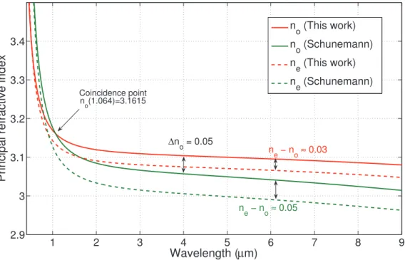
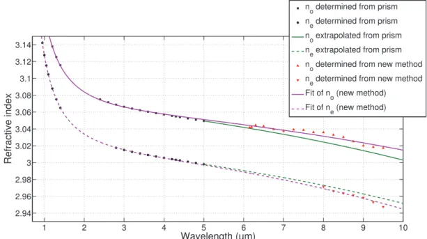
6.2 Determination of refractive indices above 6 µm 77
6.2.1 The new method 77
6.2.2 Comments 80
6.2.3 Results and discussion 80
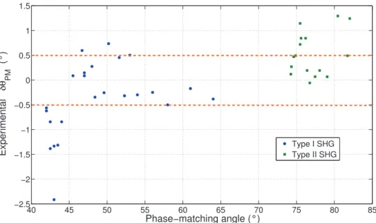
6.3 Refractive index accuracy and phase-matching measurements 81
6.3.1 Example of calculation procedure 83
6.3.2 Matrix formalism and results for CSP 84
6.3.3 Numerical results 86
6.3.3.1 Second Harmonic Generation 87
6.3.3.2 Difference Frequency Generation 90
6.4 Conclusion 93
7 infrared supercontinuum generation in csp 95
7.1 Interest of a supercontinuum 95
7.2 Theoretical treatment 95
7.3 Comparison between infrared nonlinear crystals 97
7.3.1 Optimal parameters 97
7.3.2 Spectral acceptances 99
7.4 Infrared pump lasers 101
Contents
iii widely and continuously tunable optical parametric oscillator based on a 5%mgo:ppln crystal cut as partial cylinder 105
9 5-mm-thick periodically poled 5%mgo:ppln cylinders 107
9.1 Massive QPM materials 107
9.1.1 5%MgO:PPLN versus other QPM materials 107
9.1.2 Phase-matching properties of 5%MgO:PPLN 110
9.2 Tunable quasi-phase-matched OPO 111
9.2.1 Multigratings and fan QPM samples 111
9.2.2 Cylindrical crystals 112
9.3 Our samples 112
9.3.1 From slabs to partial cylinders 112
9.3.2 Making the partial cylinders 116
10 experimental set-up and tunability 119
10.1 Experimental set-up 119
10.1.1 Pump focalisation 119
10.1.2 Cavity design and alignement 121
10.1.3 Cavity stability 123
10.2 Measuring the down-converted wavelengths 124
10.3 Wide and continuous tunability 125
10.4 Collinear or non collinear QPM ? 127
11 ramping up the generated energy 131
11.1 Intracavity signal damage 131
11.1.1 Choice of the mirrors 131
11.1.2 Increasing the signal beam radius in the cavity 132
11.2 Cavity length optimization 133
11.2.1 Constraints induced by the pump recycling 134
11.2.2 Energetical conversion efficiency and thresholds 136
11.3 Partial cylinder OPO efficiency 137
11.3.1 Generated energy 137
11.3.2 Comparison with a slab and discussion 139
12 spectral characterizations of the opo 142
12.1 Raw measurements 142
12.2 Increase in temperature 144
12.3 Spectral linewidth studies 145
12.3.1 Gain function of an OPO 146
12.3.2 Analysis of our measurements 147
12.4 Further conclusions 152
12.4.1 Simultaneous QPM 152
12.4.2 Collinear versus noncollinear QPM (second proof) 153
Contents
12.5 Conclusion on the spectral properties 157
iv dual wavelength source for versatile difference frequency generation experiments 160
13 the need for a new tool for characterizing infrared crystals 162
13.1 Specifications 162
13.2 Sources for DFG: state of the art 163
13.2.1 OPO or OPG at degeneracy 163
13.2.2 Non-parametric sources 164
13.2.2.1 Two dye lasers tunable around 700 nm 164
13.2.2.2 DFG between two laser diodes 165
13.2.3 Two independent arms 166
13.3 Conclusion 166
14 dual wavelength source with two opos in parallel 167
14.1 Our solution: principle 167
14.2 Experimental apparatus of the dual wavelength source 168
14.2.1 Experimental set-up 168
14.2.2 Beam combiner issue 169
14.3 Optimization of the spatial overlap 171
14.4 Conclusion 174
15 angular noncritical dfg in cadmium selenide 175
15.1 CdSe optical properties 175
15.2 Pump wavelength for our experiments 176
15.3 DFG Results 176
15.3.1 Experimental set-up 177
15.3.2 Angular noncritical phase-matching wavelengths 178
15.3.3 Conversion efficiency 180
15.4 Discussion 183
15.5 Conclusion 184
16 dfg experiments in small cdse crystals 186
16.1 CdSe cylinder 186
16.2 Phase-matching measurements 187
16.3 Discussion 189
16.4 Conclusion 191
Contents
Nonlinear optics has been an exciting field of research for more than 50 years triggered by the invention of the laser in 1961, which brought together the fields of parametric oscillation and optics thanks to unprecedented light powers. One of the main interest in parametric light stems from the fact that it combines some of the most desirable features of laser light such as a good coherence or a high brightness with the possibility to access wavelength ranges where no laser sources are available. In this dissertation, the infrared part of the electromagnetic spectrum will be our main focus, and we will consider wavelengths ranging from 1 to about 12 µm. There are two main reasons that drive the search for intense and coherent light sources in this part of the spectrum. The first reason comes from the transmission spectrum of the atmosphere of Earth shown on Figure (1). Our atmosphere is essentially a mixture of oxygen and nitrogen but these are the traces gases such as carbon dioxide or water vapor that contribute mostly to its transmission in the infrared: its spectrum can be split into three main transmission bands called Band I, II and III (see Figure1). In this work, we will be interested in Band II and Band III of transmission that extend respectively from 3 to 5 µm, and from 8 to 12 µm. Coherent sources in these ranges are highly desired since they can potentially lead to faster communications. On the other hand, the infrared part of the spectrum is also the kingdom of spectroscopy where rovibrational movements of molecules and bonds can be easily probed. Thanks to specific absorption bands of chemical bonds, one of the most common applications of infrared spectroscopy is the identification of chemical species. Figure (1) shows the absorption bands of the main organic and amide com-pounds. Intense sources in these specific ranges have already triggered important innovations in the fields of selective chemical microscopy, mixture analysis or infrared differential absorption lidar measurements [1]. The superiority of parametric sources over laser sources can be seen from the wide tunability that can be theoretically obtained with frequency converter devices.
The first observation of frequency conversion was Second Harmonic Generation of a ruby laser in a quartz crystal in 1961. It gave an early glimpse of how future progress in frequency converter devices would be irreparably tied to advances in both fields of lasers and materials science. Parametric infrared generation has been no exception since that day. Historically speaking, two lasers have had a tremendous impact on the search for new nonlinear infrared crystals. First of all,
Second Harmonic Generation of the CO2laser emitting around 10 µm has long been regarded
as a prerequisite to the decision of developing a new nonlinear crystal. This criterion has led to the identification of a few crystals such as ZnGeP2, AgGaSe2, AgGaS2 that are now commercially available. On the other hand this criterion of Second Harmonic Generation of the CO2 laser can prove limited either because this frequency conversion is impossible in some crystals (including CdSe), or simply because high intensity CO2 lasers are not widely available.
The most widely spread laser in the near infrared is undoubtedly the Nd:YAG laser emitting at 1.064 µm, and a specific focus has then been put on the search for infrared materials allowing an efficient parametric conversion of laser wavelengths close to 1 µm [5]. However limited success in direct generation of wavelengths above 8 µm has been seen so far, so that laser materials doped with other rare earth ions, such as Ho3+, Tm3+ or Er3+ or transition metal ions such as Cr2+
Contents
Figure 1: Illustration of the two main applications of intense coherent infrared sources and of the main laser infrared sources. This graph is taken from [2], after [3]and [4].
Contents
have been developped providing new lasers emitting at specific wavelengths in the range 2-3 µm (see [6] and Figure 1). These lasers are expected to play a key role in the generation of longer infrared wavelengths in the future. On the other hand, it is interesting to notice that despite these recent developments, there are still several nonlinear crystals with giant nonlinearities and wide transmission windows in the infrared such as CdGeAs2, Te, Se that remain underused mostly because of a lack of adequate laser sources for pumping or characterization above 3 µm [5]. We advocate in this work that the search for new nonlinear infrared materials is still highly desirable not only for fundamental but also for practical reasons. However, as Optical Parametric Oscillation can hardly be demonstrated at the early stages of the development of a new crystal because of the small sizes necessarily obtained in the very first growth attempts, it is the underlying stance of this dissertation that exploratory search, early identification and better characterizations of new and small-sized nonlinear infrared crystals requires the development of better analytical as well as experimental tools. As a consequence, this dissertation falls at the interface between the fields of materials science and that of parametric nonlinear optics.
The first Part of this work provides some theoretical background on frequency conversion in nonlinear crystals. A classical picture of Optical Parametric Oscillation (OPO) and Difference Frequency Generation (DFG) is given. These two processes both involve the fission of a photon and can therefore lead to the generation of parametric light at longer wavelengths. However, a high degree of synchronism between the interacting waves in the crystal is necessary to generate such new wavelengths. An extensive comparison is provided between Birefringent Phase-Matching and Quasi-Phase-Matching, which are the two main methods that have been developed to force a photon to fission. Emphasis is put on the versatility of the Quasi-Phase-Matching technique [7] for the generation of tunable coherent radiation in the infrared.
The second Part of this work deals with the new chalcopyrite material CdSiP2. Its unique phase-matching properties have been characterized using the sphere method. Contrary to ZnGeP2 or AgGaS2 that belong to the same family, this material is better suited for pumping with a Nd:YAG laser at 1.064 µm. In this work, we use the unique measurements of the phase-matching angles of this crystal and strive to determine its principal refractive indices with the uttermost accuracy required by the phase-matching conditions. An unusual quantitative analysis relating the accuracy of the measurements of the refractive indices of a crystal to that of the calculations of the phase-matching angles is provided. We believe that this analysis comes to fill a gap in the field of phase-matching metrology.
The two following Parts III and IV are then devoted to the design of an all-parametric source dedicated to fundamental studies of the phase-matching properties of mid to far-infrared nonlinear crystals. We first deal with the experimental realization of a widely and continuously tunable OPO that will be the cornerstone of the parametric source described in the final Part IV. This OPO is based on a 5-mm-thick crystal of 5%MgO:PPLN cut and polished to optical quality as a partial cylinder. World record conversion efficiencies for a cylindrical device as well as wide and continuous tunability from 1.4 up to 4.4 µm have been obtained. This device is perfectly suited for
Contents
applications in Band II of transmission of the atmosphere, as shown on Figure (1), but because of the limited transparency range of the crystal, generation of infrared coherent radiation in Band III is not possible with only one such device.
It is the purpose of Part IV to present how the combination of two such devices can be advantageously used to generate a tunable radiation in Band III. We have built a second partial cylinder OPO similar to the one described in Part III, so that when the two OPOs are pumped in parallel and with the same Nd:YAG laser, we dispose of a unique dual wavelength source with two independently and widely tunable beams. This is a unique and highly desirable feature of a dual wavelength source for characterizing new nonlinear infrared crystals since any parametric interaction between two beams between 1.4 and 4.4 microns can be foreseen. In this work, we used our source to perform DFG experiments in Band III between two beams independently tunable between 2.5 and 4.4 µm. Two different experiments have been carried out in CdSe crystals and confirmed the potentiality of our source. The many promises held by such a dual wavelength source will be stressed.
Parametric sources between 2 and 5 µm have now reached such a high degree of maturity [6, 7] that we find them better suited than solid-state lasers to match the requirements of new characterization tools of nonlinear crystals in the mid to far infrared.
Part I
I N T R O D U C T I O N
In this part, we consider the classical interaction between an electric field and a second order nonlinear medium. At high enough intensities, the electronic polarization induced in a material depends nonlinearly on the electric field, so that its spectrum includes additional “new” frequen-cies. In the general case, these new frequencies cannot be radiated efficiently: a constructive interference between the nonlinear polarization and the electric field it radiates is necessary to ensure an efficient generation or amplification of an optical wave. In this dissertation, we are essentially interested in the generation of optical waves in the infrared part of the electromagnetic spectrum through a three-wave mixing process, and the Difference Frequency Generation (DFG) process is our main focus.
In the first chapter, the linear and nonlinear polarizations induced in uniaxial crystals are derived. The electric field radiated by the second-order nonlinear polarization is then obtained as the solution of the Maxwell’s equations. The resulting coupled equations governing the amplitudes of each Fourier component of the electric field are figured out. The phase velocities of the second-order nonlinear polarization and of the radiated electric field must be matched to ensure an efficient three-wave parametric mixing process. And in the second chapter, we discuss two different strategies that will ensure the efficient generation or amplification of a wave at a given optical frequency. Historically, the first strategy has been birefringent phase matching (BPM) where the required constructive interference is obtained in an anisotropic material: the dispersion is exactly compensated by the birefringence of the material in the considered direction of propagation. The second scheme is called quasi-phase matching (QPM): through a proper modulation of the sign of the non-linearity inside the material, the efficient growth of a new optical wave can be obtained even if the phase velocities are not matched. The solution of the coupled equations is given for typical DFG processes in each case. The advantages of QPM over BPM are also discussed.
Even if the phase matching condition is fulfilled, DFG conversion efficiencies in nonlinear crystals are often still low, and the third chapter is dedicated to the phenomenon of Optical Parametric Oscillation (OPO) that overcomes this limitation. Actually, the resonance of one of the newly generated wave leads to an “artificial” increase of the interaction length in the nonlinear crystal. Provided the nonlinear gain is high enough to compensate for the losses of the cavity, pump photons are efficiently converted into two photons with lower energies. OPOs are therefore very interesting devices when new wavelengths in the infrared must be efficiently generated. It is the advent of QPM materials that has contributed to a renewed interest in OPO devices.
1
PA R A M E T R I C T H R E E WAV E M I X I N G
1.1 classical treatment
We consider in this section the polarization induced by an electric field in a noncentrosymmetric crystal. The electric field is real and assumed to be the superposition of three waves at frequencies
ω1, ω2and ω3 . It writes: ~ E(~r, t) =
∑
n=1,2,3 ~ En(~r, t) (1) where −→ En(−→r , t) = Re(~E(r, ωn)ejωnt) = 1 2(~E(r, ωn)e jωnt+ ~E(r, ω n)∗e−jωnt) (2) with ~E(r,−ω n) = ~E(r, ωn)∗ (3)The spectrum of the full electric field is therefore made of six terms at the circular frequencies
±ω1,±ω2 and±ω3.
Besides, the time dependent polarization induced by the electric field is assumed to be written [8] under the form :
1.1 classical treatment ~ P(~r, t) =ε0 +∞ ˆ −∞ R(1)(τ1):~E(~r, t−τ1)dτ1 +ε0 +∞ ˆ −∞ +∞ ˆ −∞ R(2)(τ1, τ2) ∴ ~E(~r, t−τ1) ⊗E(~~ r, t−τ2)dτ1dτ2 (4) +... +ε0 +∞ ˆ −∞ +∞ ˆ −∞ R(n) .. . (τ1, ..., τn):~E(~r, t−τ1) ⊗...⊗E(~~ r, t−τn)dτ
where R(n) are n+1 order tensors fulfilling the causality condition and describing the nth order impulse response of the material.
By combining the Maxwell’s equations, one finds the Helmholtz equation (5) satisfied by the electric field in a nonmagnetic and lossless medium. The polarization termP~ given in Equation (4) acts like a source term of the electric fieldE~:
∇2E −~ 1 c2 ∂2~E ∂t2 =µ0 ∂2P~ ∂t2 (5)
By taking the Fourier Transform of Equation (4), one can get the Fourier components of the polarization induced in the material by the electric field at any pulsation ω∈ R+(see Equation3):
~P(~r, ω) =P~(1)(~r, ω) +P~(2)(~r, ω) +...+P~(n)(~r, ω) (6)
The first order term P~(1) is the linear electronic polarization, while the P~(n) components
constitute the nth-order nonlinear electronic polarizations. In the Fourier domain, Equation (5) yields the partial derivative equation governing the amplitude of each Fourier component of the electric field : ∀ω∈R+,∇2~E(~r, ω) + ω 2 c2~E(~r, ω) = − ω2 c2ε 0 ~P(~r, ω) (7)
1.1 classical treatment
1.1.1 Linear optics in uniaxial crystals
The first order Fourier component of the polarisation at ω is given by a linear term in the electric field component :
~
P(1)(~r, ω) =ε
0χ(1)(ω).~E(~r, ω) (8)
We have introduced the first order susceptibility tensor χ(1)(ω), which is the Fourier Transform
of the first order impulse response of the material. The real and imaginary parts of this tensor describe the linear properties, propagation as well as absorption phenomena respectively, of an electromagnetic wave at the circular frequency ω in the material. Formula (8) shows that the spectrum of the electric field is necessarily the same as the spectrum of the linear polarization.
In the linear case, the Helmholtz equation reduces to:
∀ω∈R+,∇2~E(~r, ω) + ω
2 c2(1+χ
(1)(ω))~E(~r, ω) =0 (9)
The number of independent eigenvalues of the relative dielectric permittivity tensor ǫr(ω) = 1+χ(1)(ω)sets the optical class of the crystal: for a triply degenerate eigenvalue, the crystal is isotropic; for two eigenvalues, one of which being degenerate, the crystal belongs to the uniaxial class; and for three independent eigenvalues, the crystal belongs to the biaxial class. The optical class of a crystal is set by its crystalline symmetry [8]. In this dissertation we will be dealing with crystals belonging to the uniaxial class only. For uniaxial crystals, the(x, y, z)optical frame, also called the dieletric frame, is the frame where the susceptibility and dielectric permittivity tensors are both diagonal. In this frame, the x and y axis are equivalent while z is called the optical axis of the crystal. And ǫr(ω)writes:
ǫr(ω) = 1+χxx(ω) 0 0 0 1+χxx(ω) 0 0 0 1+χzz(ω) (10)
For a lossless medium, this tensor is real. We can then define two principal refractive indices no(ω), the ordinary index, and ne(ω), the extraordinary index through
n2o(ω) =1+χxx(ω) (11)
and
1.1 classical treatment
If ne > no the uniaxial is said to be positive, and if ne < no, it is said to be negative. For an arbitrary direction of propagation~u(θ, φ),
~u(θ, φ) = sin θ cos φ sin θ sin φ cos θ (13)
where θ and φ are the angles of spherical coordinates in the optical frame, the refractive index of a wave at the circular frequency ω can then take two different values given by:
no(ω, θ, φ) =no(ω) ne(ω, θ, φ) = (cos 2θ n2 o(ω) + sin 2θ n2 e(ω) )−1/2 (14)
The ordinary index no corresponds to an ordinary polarized wave, meaning that its direction of polarization~eo is always perpendicular to the optical axis z and to the Poynting vectorΠ~o. The extraordinary index is that of a wave whose polarization vector~ee is perpendicular to~eo, and to the Poynting vectorΠ~ebut not to the z-axis. When an extraordinary polarized wave propagates in a direction~u(θ, φ)with θ6=0° or θ 6=90°, the Poynting vectorΠ~eand the wavevector~ke are not parallel: there exists an angle called the walk-off angle between them. This angle ρ is given in [9]. For positive uniaxial crystals, it writes:
ρ+(θ, ω) =θ−arctan(n 2 o(ω) n2 e(ω) tan(θ)) (15)
For negative uniaxial crystals, it writes:
ρ−(θ, ω) =arctan(n 2 o(ω) n2 e(ω) tan(θ)) −θ (16)
The magnitude of this angle increases with the birefringence (ne−no) of a material. It is the highest for θ =45° and vanishes for θ=0° or θ =90°. The direction of polarisation of ordinary and extraordinary waves can then be expressed in the spherical coordinates linked to the optical frame through : ~ eo = −sin φ cos φ 0 ~ee = −cos(θ±ρ∓(θ))cos φ −cos(θ±ρ∓(θ))sin φ sin(θ±ρ∓(θ)) (17)
where −ρ+ must be used for the positive class, and +ρ− for the negative class [8]. The fact that an extraordinary and an ordinary wave propagating in a uniaxial crystal at θ = 90° from
1.1 classical treatment
the optical axis are not spatially separated has very important consequences in nonlinear optics and leads to angular noncritical phase-matching (see section2.1.3). Otherwise, such two waves will be spatially separated after a length that depends on the size of the beams and conditions of focalisation which eventually limits the conversion efficiency of a three-wave mixing process.
(a) Positive uniaxial crystals (b) Negative uniaxial crystals Figure 2: Index surface of uniaxial crystals.
The ordinary and extraordinary layers of the index surfaces are sketched in Figure (2) for optically positive and negative uniaxial crystals, based on Equations (14). The ordinary surface is spherical whereas the extraordinary surface is elliptical. These two surfaces intersect along the optical axis z and the crystal is optically isotropic along this direction of propagation.
1.1.2 Nonlinear polarization
Generally speaking, when two waves at ω1 and ω2 are incident upon the crystal the new
circular frequencies of the nonlinear polarization can be 0(= ω1−ω1 = ω2−ω2), 2ω1(= ω1+ω1), 2ω2(= ω2+ω2), ωSFG = ω1+ω2 and ωDFG1 = ω2−ω1, ωDFG2 = ω2−ω1. These six angular frequencies correspond respectively to six different physical processes of three-wave mixing: Optical Rectification, Second Harmonic Generation of the wave at ω1, Second Harmonic Generation of the wave at ω2, Sum Frequency Generation (SFG) between the wave at ω1and the wave at ω2, and Difference Frequency Generation (DFG) between the wave at ω2and the wave at ω1, or Difference Frequency Generation between the wave at ω1and the wave at ω2. Any wave with an angular frequency different from the six possibilities mentioned above cannot interact with the two other waves through a second order nonlinear process.
The energy conservation between three waves at ω1, ω2and ω3 satisfying ω1 ≤ω2 <ω3is:
1.1 classical treatment
In the case of Sum Frequency Generation between two waves at ω1 and ω2 for example,
the Fourier component of the second order nonlinear polarization P~(2)(~r, ω
SFG) in Equation (6) is related to the Fourier transform of the second order impulse response of the material
χ(2)(ωSFG =ω1+ω2)through: ~
P(2)(~r, ω
SFG= ω1+ω2) = ε0χ(2)(ωSFG =ω1+ω2)...~E(~r, ω1) ⊗~E(~r, ω2) (19)
We will see in the next section that an electric field at a new frequency is radiated efficiently only if the nonlinear polarization at this new frequency interferes constructively with the generated electric field it radiates at the same frequency. This is so if the phase matching condition is fulfilled.
1.1.3 Coupled equations for propagating waves
In this section, we consider three collinear plane waves at ω1, ω2 and ω3satisfying the energy conservation relation (18) and propagating in a noncentrosymmetric crystal. The crystal is assumed to be without losses at the given frequencies, and the diffraction and spatial walk-off effects are neglected. These waves propagate along a direction~u(θ, φ)in the crystal with ξ being the coordinate along this direction of propagation. If these waves are assumed to be linearly polarized along the unit vectors~e1,~e2,~e3, the Fourier component at ωnthen writes:
−→
En(−→r , ωn) =An(ξ)e−jknξe~n (20)
The complex amplitude of the field at ωnis called Anand we assume a priori that this amplitude can change along the propagation in the crystal. The wave vectorsk~nare collinear to~u(θ, φ)with amplitudes given by:
kn=
n(ωn)ωn
c =
2π
λnn(ωn) (21)
where n(ωn)is the index of refraction of the wave at ωn in the considered direction of propaga-tion.
By keeping the first and second order terms, Equation (6) writes:
~P(~r, ω) ≈P~(1)(~r, ω) +P~(2)(~r, ω) (22)
When plugging this equation into (7), it can be seen that the second order nonlinear polarisation acts like an additional source term in the Helmholtz equation that writes:
∇2~E(~r, ω) +ε r(ω)ω 2 c2~E(~r, ω) = − ω2 c2ε 0 ~ P(2)(~r, ω) (23)
As we have assumed that the electric field comprises only three Fourier components satisfying the energy conservation relation, it can be shown that except for a degenerate case (excluded
1.1 classical treatment
here), this is the only triplet satisfying such energy conservation relation. Therefore the nonlinear polarization spectrum has only three a priori nonzero components at respectively ω1, ω2and ω3. Equation (19) gives: ~ P(2)(~r, ω 3) = ε0χ(2)(ω3 =ω1+ω2)...~E(~r, ω1) ⊗~E(~r, ω2) ~ P(2)(~r, ω 2) = ε0χ(2)(ω2 =ω3−ω1)...~E(~r, ω3) ⊗~E∗(~r, ω1) ~ P(2)(~r, ω 1) = ε0χ(2)(ω1 =ω3−ω2)...~E(~r, ω3) ⊗~E∗(~r, ω2) (24)
Each Fourier component of the nonlinear polarization is created by the coupling of the two other fields through the second order susceptibility tensor. The nonlinear polarization at ω3is induced by the Fourier component of the fields at +ω1 and +ω2. The nonlinear polarization at ω1 (and ω2) are induced by the Fourier component at +ω3 and −ω2 (+ω3 and −ω1). This justifies (see Equation3) the presence of the conjugate of the Fourier component of the electric field~E∗(~r, ω2)and~E∗(~r, ω1)respectively in Equations (24).
When assuming a lossless medium and a low frequency dispersion of the nonlinear medium, the three susceptibility terms in Equation (24) can be considered as equal, i.e:
χ(2)(ω3) =χ(2)(ω2) =χ(2)(ω1) =χ(2) (25)
This corresponds to the ABDP symmetry [10]. It will be the framework of the following calculations. We also consider the approximation of the slowly varying envelope which assumes that the spatial variation of the envelope along the~u direction is small on a distance comparable with the wavelength. This is the case if the nonlinear interaction is weak enough. Then, it is correct to assume that
∂2A n ∂ξ2 ≪ 2jkn ∂An ∂ξ ∝ 1 λn ∂An ∂ξ (26)
The full system governing the amplitudes of the fields in the crystal is: ∂A1 ∂ξ = −jω1 2n(ω1)cA3A ∗ 2χe f fe−j∆kξ ∂A2 ∂ξ = −jω2 2n(ω2)cA3A ∗ 1χe f fe−j∆kξ ∂A3 ∂ξ = −jω3 2n(ω3)cA1A2χe f fe j∆kξ (27)
1.1 classical treatment
This first order nonlinear system provides the coupled equations governing the evolution of the complex amplitudes of the three interacting waves in the crystal.
We have introduced two key parameters of a second order parametric process: the collinear phase mismatch ∆k and the effective coefficient χe f f:
∆k=k3−k2−k1 (28)
and
χe f f = ~e1.χ(2)...e~3⊗ ~e2 = ~e2.χ(2)...e~1⊗ ~e3= ~e3.χ(2)...~e1⊗ ~e2 (29)
The expression of the effective coefficient χe f f involves the three directions of polarization of the interacting waves. This coefficient is invariant upon any permutation of these three vectors [10]. The importance of this coefficient will be discussed extensively in the BPM section (2.1.2). It is common to define the nonlinear effective coefficient as :
de f f = 1 2χe f f (30) We also put an= An √ 2Zn¯hωn (31) as well as κ=de f f v u u t 2ω1ω2ω3 c2n(ω 1)n(ω2)n(ω3)¯hZ0 (32)
where Z0is the vaccum free impedance (Z0 =377 Ω)and Zn is the impedance of the medium at ωn: Zn=
Z0
n(ωn), so that system of coupled equations is reduced to: ∂a1 ∂ξ = −jκa3a2∗e− j∆kξ ∂a2 ∂ξ = −jκa3a ∗ 1e−j∆kξ ∂a3 ∂ξ = −jκa1a2e j∆kξ (33)
These new variables are useful since now the intensity In of a wave at the frequency ωn is proportional to the photon flux density|an|2:
1.2 difference frequency generation
In= ¯hωn|an|2= 1
2n(ωn)ǫ0c|An|
2 (34)
And one can show that the coupled equations imply the Manley Rowe relations: d(|a1|2) dξ = d(|a2|2) dξ = −d(|a3|2) dξ (35)
These equations state that in a three wave parametric process, the annihilation of a photon at
ω3always goes along with the creation of two photons, at ω1and ω2: the global photon number is not conserved in a parametric process, contrary to the sum of the intensities of the three waves.
1.2 difference frequency generation
1.2.1 Principle
So far, three waves at ω1, ω2 and ω3 satisfying ω1 ≤ ω2 < ω3 and ω1+ω2 = ω3 have been considered. From now, the circular frequencies of these waves are called ωp, ωs and ωi for the pump, signal and idler waves respectively, and the condition ωi ≤ωs<ωp is valid. Difference Frequency Generation consists in the generation of a wave at the circular frequency ωi from two initial waves at ωp and ωsso that :
ωi =ωp−ωs (36)
We are interested here in the efficiency of the generation of a wave at ωi. The intensity of this wave in the crystal is governed by the system of coupled equations (33). Fully analytical solutions of this system can be worked out, without assumptions on the relative intensities of the three waves. This was done in 1962 in the seminal paper of nonlinear optics [10], but we do not give this full solution here. We would rather make some necessary and realistic assumptions so that the system (33) can be further simplified and solved out.
1.2.2 Solution in the case of no depletion
In a typical case of DFG between one wave at ωp and one wave at ωs, the intensities of the two incoming waves are comparable. The efficiency of conversion at ωi =ωp−ωsis usually low enough so that the amplitudes of the two incident waves Ip,0 and Is,0(with corresponding reduced amplitudes ap,0 and as,0) can be regarded as constant throughout the crystal of length L. This assumption, called the undepleted pump approximation (UPA), was discussed elsewhere [11] and has the main advantage of giving a result that can be easily and physically interpreted. In this case, the system (33) gets down to only one equation governing the amplitude of the new wave at
1.2 difference frequency generation
∂ai
∂ξ = −jκap,0a
∗
s,0e−j∆kξ (37)
After a length L, the amplitude and intensity of the wave at ωi turn out to be:
ai(L) = −jκap,0as,0Le−j ∆k 2 Lsinc( ∆kL 2 ) (38) and Ii(L) = 2ωi2 n(ωi)n(ωs)n(ωp)Z0d 2 e f fIp,0Is,0L2sinc2( ∆kL 2 ) (39)
This behavior is typical of an interference: the two waves that interfere in the crystal are the nonlinear polarization at ωi and the electric field at the same frequency. The amplitude of the electric electric field grows in the crystal if this interference is constructive. When the phase mismatch ∆k is not nil, these two waves do propagate in the crystal at different phase velocities: after propagation over a length Lcgiven by
Lc = π
|∆k| (40)
these two waves get dephased by a factor of π, so that the interference is successively constructive and destructive. However, if the phase-mismatch is zero, then the coherence length on which the energy transfer can take place is supposedly infinite, and only restricted by the crystal length available L. This is the optimal situation for a high conversion efficiency. This condition ∆k =0 is the phase-matching condition. In the case of three collinear interacting waves, it writes, in the direction of propagation considered :
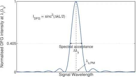
∆k=0⇐⇒ n(λλp) p = n(λs) λs +n(λi) λi (41) We have plotted a typical gain curve of a DFG process in Figure (3). The intensity of the wave at λi is given as a function of the wavelength λs. The pump wavelength is assumed to be set at a constant value λp. Thus, the wavelength λi satisifies the energy conservation relation for each value of λs (see Equation18):
λi = ( 1 λp− 1 λs) −1 (42)
The wavelength λs,PM corresponding to the maximum of Equation (39) satisfies the phase-matching condition ∆k(λs,PM) = n(λp) λp − ( n(λs,PM) λs,PM + n(λi,PM) λi,PM ) =0 (43)
1.2 difference frequency generation 0 0.405 1 Signal Wavelength Normalised DFG intensity at λ i ( λ s ) λ s,PM Spectral acceptance ∆λ s I DFG ∝ sinc 2 (∆kL/2)
Figure 3: Normalized intensity of the generated idler wave at λi as a function of the signal wavelength λs, from Equation (39).
The gain on the idler is the highest for this signal wavelength. But waves with phase mismatches that satisfy the condition
|∆k| < 2π
L (44)
can still be amplified. The longer the crystal, the narrower this spectral acceptance. It is usual to consider that the acceptance of a phase matching process is given by the range of wavelengths satisfying sinc(∆kL 2 ) 2 ≥ 2π !2 ≈0.405 (45)
In this case, the phase-mismatch condition writes:
|∆k|0.405 < π
L (46)
This is a general feature of phase-matching conditions. Whenever phase-matching is obtained for a given parameter αPM (such as temperature, angle, dopant concentration etc...) there is always a range of α parameters around αPM that will contribute to the parametric processes with a non negligible intensity. Spectral acceptances are of prime importance in nonlinear parametric processes. More work on the specific acceptances of Birefringent Phase Matching and Quasi-Phase Matching will be discussed in sections (2.1.3) and (2.2.3).
1.2.3 Quantum interpretation
Difference Frequency Generation can be seen as the fission of the high frequency photon at ωp into two photons of lower frequency (ωs and ωi). The phase-matching condition and
1.3 optical parametric amplification
(a) Spontaneous photon splitting (i.e. parametric fluorescence)
(b) Stimulated photon splitting (i.e. optical parametric amplification at ωsand DFG
at ωi) Figure 4: 3-photon scission schemes
(a) Collinear phase-matching (b) Noncollinear phase-matching
with angles α (and β) between the signal (and idler) and the pump momenta.
Figure 5: 3-photon momentum conservation schemes
energy conservation relation can be understood as conservation relations in a scattering process between three photons at ωp, ωs and ωi. The energy conservation relation can be restated as ¯hωp = ¯hωs+¯hωi which is nothing else than the energy conservation between one photon at ωp and two photons at ωsand ωi. The scattering process can be either spontaneous or stimulated (See Figure4), meaning that the fission of a pump photon can happen spontaneously or through the stimulation by another signal photon. As for the phase matching condition, it should be interpreted as the momentum conservation relation ¯hk~p= ¯h~ks+¯h~ki. In the collinear case, the three photons have their momenta along the same direction. In the noncollinear case, the momenta are no longer aligned (see Figure5).
1.3 optical parametric amplification 1.3.1 Solutions in the Undepleted Pump Approximation
In this section, contrary to what was assumed for a DFG conversion process, only the depletion of the pump wave is negligible. On the opposite, the amplitude of the two other waves can evolve in the crystal. Then, the system of coupled equations becomes:
1.3 optical parametric amplification ∂ai ∂ξ = −jκap,0a∗se−j∆kξ ∂as ∂ξ = −jκap,0a∗ie−j∆kξ (47) By combining these two equations, one finds that as and ai fulfill the same following partial differential equation: ∂2a ∂ξ2 +j∆k ∂a ∂ξ −γ 2 0a=0 (48)
where we have defined the gain coefficient γ0as:
γ20 =κ2 Ip,0 ¯hωp = 2ωsωid 2 e f f c2n(ω s)n(ωi)n(ωp)Z0Ip,0 = 8π 2d2 e f f λsλin(λs)n(λi)n(λp)Z0Ip,0 (49)
We also define the pseudo-gain coefficient γ through:
γ2 =γ20− (∆k
2 )
2 (50)
Depending on the relative values of the phase mismatch and of the intensity of the pump wave, the behavior of the complex amplitudes of the fields is dramatically different. The exact solution depends on the relative position of ∆k and γ0 so that γ can be either purely real or purely imaginary. In the realistic case where one wave at λs is incident on the crystal, (still in addition of a strong and undepleted pump), the initial boundary conditions write ai(0) =a∗i(0) =0 and we get the solution of (47):
ai(L) =ja∗s(0) κap,0 γ sinh(γL)e− j∆k2 L as(L) =as(0)[cosh(γL) +j ∆k 2γsinh(γL)]e− j∆k2 L (51)
From there we can derive the intensity of the two waves in the crystal: Ii(L) = Is(0) λs λi γ2 0 γ2sinh 2(γL) Is(L) =Is(0)[1+ γ2 0 γ2sinh 2(γL)] (52)
It appears that the intensities of the signal and idler waves increase in the crystal (see Figure6), including the generation of new optical wave at λi and the amplification of the other wave at λs. This phenomenon corresponds to Optical Parametric Amplification (OPA) and is the principal mechanism involved in Optical Parametric Oscillators.
In the limit of very low gains (in the first order in γ20, and for arbitrary ∆k), the formulas (52) can be simplified in:
1.3 optical parametric amplification Ii(L) ≈ Is(0) λs λi γ2 0L2sinc2( ∆kL 2 ) Is(L) ≈Is(0) (53)
These two formulas coincide with the expressions derived in section (1.2.2) for the DFG situation. At small gains the DFG equation does provide a good approximation of the intensity generated at
λi, while the amplification at λscan be neglected.
When the phase-mismatch vanishes (∆k =0, γ0 arbitrary), the formulas (52) give: Ii(L) =Is(0) λs λi sinh2(γ0L) Is(L) = Is(0)cosh2(γ0L) (54)
And for high gains in formulas (52), the intensities are approximated by: Ii(L) = 1 4Is(0) λs λie 2γL Is(L) = 1 4Is(0)e 2γL (55)
This shows that for large gains, the intensities of the waves grow exponentially in the crystal (see insert of Figure6). And the meaning of γ0and γ as amplification coefficients is now clear. These coefficients increase when the pump intensity increases (see Equation49). For high conversion efficiencies, the pump will start to be depleted, and the solutions of the coupled equations provided here are no longer valid. At this point, pump depletion must be taken into account, and the elliptical functions must be used to derive the proper solution of the coupled equations [10]. 1.3.2 Comments and numerical estimates
First of all, it is important to notice that the gain coefficient given in Equation (49) is very dispersive. If we exclude the dispersion of the effective coefficient, the product ωsωi shows that the gain coefficient, γ0, is the highest at degeneracy for
ωs=ωi =
ωp
2 (56)
This is an important remark for our future work in Part III: it is usually more difficult to trigger the oscillation of an OPO far from degeneracy.
In this dissertation, we will be dealing mainly with two different crystals CdSe and 5%MgO:PPLN for which we provide two numerical estimates of the gain coefficient. These values are not only useful for the sake of comparison but also for the prospects of CW OPO operation (see section
3.2.2). The gain coefficient of CdSe is worked out for typical values corresponding to angular noncritical phase-matching (θ =90◦). For a pump, signal and idler wavelength at respectively 2.7,
1.3 optical parametric amplification 0 0.2 0.4 0.6 0.8 1 1.2 1.4 1.6 1.8 2 0 0.5 1 1.5 2 2.5 3 3.5 4 4.5 5 γ0L I signal,idler (L)/I signal (0) 0 0.5 1 1.5 2 10−2 10−1 100 101 γ 0L I(L)/I s (0) Signal at λ s Idler at λ i = 2.5λs
Figure 6: Example of intensities of the amplified signal and generated idler waves in an Optical Parametric Amplifier. The exponential behavior at high gains predicted in Equation (55) is shown in insert on a logarithmic plot.
4.0 and 8.3 µm, an effective coefficient de f f =18 pm/V, and a pump intensity Ip,0 =30 MW/cm2, we find:
γ02=0.57 cm−2 (57)
As for 5%MgO:PPLN, we take here numerical values typical of the OPO described in Part III. The pump wavelength is 1.064 µm and the downconverted signal and idler wavelengths are taken far from degeneracy ( λs =1.45 µm and λi =4.0 µm). For the sake of comparison, we take the same pump intensity as for the calculations in CdSe. And the effective coefficient for the QPM process is here de f f =
2
πd33= −17.3 pm/V (See section2.2.2.2and reference [12]). We find:
γ02=4.8 cm−2 (58)
The gain coefficient is therefore almost 3 times higher in 5%MgO:PPLN sample than in CdSe. This discrepancy comes from the fact that the idler and pump wavelengths considered in the case of CdSe are longer than in 5%MgO:PPLN.
The last comment that can be done here is about the ratio of the wavelengths appearing in Equations (53) or (54). For a given idler wavelength, the idler conversion efficiency is proportional to the ratio between the signal and the idler wavelengths, which increases with the pump wavelength as shown on Figure (7). The efficiency of conversion of a given idler wavelength is higher if longer pump wavelengths are used: the quantum defect is reduced. This is an important feature of Optical Parametric Amplification.
1.3 optical parametric amplification 1 1.25 1.5 1.75 2 2.25 2.5 2.75 3 0 0.1 0.2 0.3 0.4 0.5 0.6 0.7 Pump wavelength (µm) λ s / λ i λ i = 8 µm λ i = 12 µm
Figure 7: Influence of the pump wavelength on the ratio between the signal and idler wavelength
λs
λi appearing in Equation (
2
B I R E F R I N G E N T P H A S E - M AT C H I N G V E R S U S Q U A S I - P H A S E - M AT C H I N G
2.1 birefringent phase-matching 2.1.1 Principle
In an isotropic crystal with normal dispersion over the range λp and λi , the phase-matching relation (41) cannot be fulfilled. But, in an anisotropic medium, such as an uniaxial crystal, since the index of a wave can take two values, n+(λ)or n−(λ), with the convention n−(λ) <n+(λ), it is possible to achieve the phase-matching condition. Among the 23=8 different configurations of polarizations allowed in a three wave process, it is necessary but far from being sufficient for the highest circular frequency wave (or pump wavelength) to propagate along the fast axis of the crystal. In its most general form, the BPM condition then writes [13]:
n−(λp, θ) λp = n−,+(λs, θ) λs + n−,+(λi, θ) λi (59)
with three possible different configurations called Type I, Type II and Type III depending on the idler and signal polarizations. In this work, Type I corresponds to the two waves λsand λi with the same polarization, whereas Type II is chosen to be the configuration with the signal λs in the same state of polarization as the pump. The extraordinary refractive index varying with the direction of propagation in the crystal (Equation 14), the phase mismatch parameters are functions of the azimuthal angle θ in uniaxial crystals, and Table (1) gives the expression of the phase matching condition for the three types in unaxial negative and positive crystals.
For a given set of wavelengths {λp,λs, λi} satisfying the energy conservation relation and with λp <λs ≤ λi, phase matching condition is usually not satisfied for a random direction of propagation in a crystal. The angle of propagation θ must be chosen equal to the phase-matching angle θPM defined by ∆k(θPM) =0. The requirements on the birefringence of the crystal to fulfill the BPM condition have been discussed elsewhere [13]. Except for Type II and Type III of positive uniaxial crystals and Type I of a negative uniaxial crystals, there is no analytical solution for the phase matching angle θPM since two extraordinary waves are involved in Equation (59). Numerical estimates can be found in [9].
2.1 birefringent phase-matching Type I ne(λp, θ) λp = no(λs) λs +no(λi) λi Type II ne(λp, θ) λp = ne(λs, θ) λs + no(λi) λi Type III ne(λp, θ) λp = no(λs) λs +ne(λi, θ) λi
(a) Negative uniaxial crystals (ne<no)
Type I no(λp) λp = ne(λs, θ) λs + ne(λi, θ) λi Type II no(λp) λp = no(λs) λs +ne(λi, θ) λi Type III no(λp) λp = ne(λs, θ) λs + no(λi) λi
(b) Positive uniaxial crystals (ne>no)
2.1 birefringent phase-matching
It is important to notice that when the energy conservation relation (42) is taken into account, the BPM condition (59) reduces to three unknowns: the pump wavelength λp, the signal wavelength λs, and the direction in the crystal θ.
It is common to set the pump wavelength to a given value, such as a typical common laser wavelength, and to look for the phase-matching signal wavelength λs,PM at different phase matching angles θPM. The curve giving the phase-matching wavelengths as a function of the phase matching angle is called the angular tuning curve of the crystal. But the other option is to keep the angle constant (so that the effective coefficient is maximum for example) and to look for the phase-matching signal wavelength at different pump wavelengths.
2.1.2 Effective coefficient
It is clear from Equation (39) that the effective coefficient should not vanish in order to have an efficient generation of a new optical wave. In BPM, the effective coefficient is given by Equation (29) as a contraction product between the second order nonlinear susceptibility tensor and the unit vectors of the polarization waves e~−p(θ, φ),es+~,−(θ, φ),e~+i ,−(θ, φ):
χe f f =e~−p(θ, φ).χ(2)...e+s~,−(θ, φ) ⊗e+i~,−(θ, φ) (60)
The second order susceptibility tensor for DFG has in the most general case 27 independent coefficients. Under Kleimann [14] and ABDP symmetries [10], the dispersion of the second order susceptibility is neglected and it is valid to calculate the effective coefficient of any three-wave-mixing process with the contracted tensor d(2) corresponding to Second Harmonic Generation,
and that has only 18 components. This tensor writes:
d(2)= d11 d12 d13 d14 d15 d16 d21 d22 d23 d24 d25 d26 d31 d32 d33 d34 d35 d36 (61)
The number and position of zero coefficients dij =0 are imposed by the symmetry of the crystal [15]. In addition, under Kleinmann symmetry, some relations between the non-zero dij coefficients can be derived [14]:
d21= d16, d25=d36, d26= d12, d31 =d15, d32=d24, d34= d23, d35 =d13, d36 =d14 (62) In the case of an uniaxial crystal, the polarization vectors are given in Equation (17) for the ordinary and extraordinary rays, and the effective coefficients can be worked out for different crystal classes. We will be using these coefficients several times in this dissertation. That is why we recall here the effective coefficients for all the uniaxial crystal classes when the walk-off angles are neglected [9].
2.1 birefringent phase-matching
Crystal classes Negative crystals Type I: λ
e
p, λos, λoi
Positive crystals Type II and III: λop, λos, λei and λop, λes, λoi
4, 4mm, 6, 6mm d15sin θ
¯6m2 d22cos θ sin 3φ
3m d15sin θ−d22cosθ sin 3φ
¯6 (d11cos 3φ−d22sin 3φ)cos θ
3 (d11cos 3φ−d22sin 3φ)cos θ+d15sin θ
32 d11cos θ cos 3φ
¯4 (d14sin 2φ+d15cos 2φ)sin θ
¯42m d36sin θ sin 2φ
Crystal classes Negative crystals Type II and III: λ e
p, λes, λoi and λep, λos, λei Positive crystals Type I: λo
p, λes, λei
4, 4mm, 6, 6mm 0
¯6m2 d22cos2θ cos φ
3m d22cos2θ cos 3φ
¯6 (d11sin 3φ+d22cos 3φ)cos2θ
3 (d11sin 3φ+d22cos 3φ)cos2θ
32 d11cos2θ sin 3φ
¯4 (d14cos 2φ−d15sin 2φ)sin 2θ
¯42m d36sin 2θ cos 2φ
Table 2: Effective coefficients of positive and negative uniaxial crystals for the three types of phase matching, when walk off is neglected and under Kleinmann assumption [9].
2.1 birefringent phase-matching
2.1.3 Angular acceptances and noncritical phase matching
For values θ close to the phase matching angle θPM , the interference function described in Equation (39) has not dropped substantially, meaning that the conversion efficiency can still be non negligible. This range of θ angles is called the angular acceptance of the crystal. It can be worked out with a Taylor Young expansion of the phase mismatch around the value θPM :
∆k(θ) ≈∆k(θPM) + (θ−θPM) ∂∆k ∂θ ! θ=θPM +1 2(θ−θPM) 2 ∂ 2∆k ∂θ2 ! θ=θPM (63) The first nonzero term of this expansion is related to the acceptance of the nonlinear process. If the first order term dominates, then the condition (45) writes:
|θ−θPM| ≤ 2π L ∂∆k ∂θ ! θ=θPM −1 (64) And the acceptance of the crystal varies as the inverse of the length of the crystal. If the first order term is null then the second order term dominates, and the condition (45) writes:
|θ−θPM| ≤ v u u u t 4π L ∂2∆k ∂θ2 ! θ=θPM −1 (65) The acceptance of the crystal varies then as the inverse of the square root of the length of the crystal.
The first case corresponds to a so-called critical phase matching situation (See Figure 8a), whereas the second case is a noncritical phase-matching situation (See Figure 8b). These two situations are very different in terms of tuning strategy for example. A very critical case will be favored when a wide range of wavelengths must be covered with a very small change in the angle of propagation. The noncritical phase-matching situation has to be favored when a wide range of wavelengths can be accessed with a broader change in angle. The angular tuning rate in noncritical phase-matching situations is of course much lower, yielding better control as well as higher accuracies.
It can be shown that noncritical phase-matching in an uniaxial crystal is achieved whenever the phase-matching angle lies in the (xy) plane of the crystal. In this case θPM =90° and the walk-off angle ρ(θPM)given in Equation (15) vanishes. This situation is very favorable because the waves do not suffer from any spatial deviation, which allows a higher conversion efficiency due to a longer interacting length. Besides, the noncritical phase-matching scheme is very favorable when dealing with pointing instabilities.
2.1 birefringent phase-matching 0 0.405 1 θ angle Normalised DFG intensity 0 θ angle ∆ kL θ PM θ PM
(a) Critical phase-matching scheme.
0 0.405 1 θ angle(°) Normalised DFG intensity 0 θ angle(°) ∆ kL θ PM θ PM
(b) Noncritical phase-matching scheme.


![Figure 17 : Comparison between the absorption coefficient of CdSiP 2 and ZnGeP 2 . This graph is taken from [42].](https://thumb-eu.123doks.com/thumbv2/123doknet/14559629.726342/63.892.235.662.413.701/figure-comparison-absorption-coefficient-cdsip-zngep-graph-taken.webp)
![Figure 19 : Effective figure of merit of the main nonlinear crystals as a function of their wavelength cut-on, from [56]](https://thumb-eu.123doks.com/thumbv2/123doknet/14559629.726342/65.892.230.671.103.440/figure-effective-figure-merit-nonlinear-crystals-function-wavelength.webp)
![Figure 20: Measured and extrapolated values of the principal refractive indices of CSP, from [42]](https://thumb-eu.123doks.com/thumbv2/123doknet/14559629.726342/66.892.244.642.115.374/figure-measured-extrapolated-values-principal-refractive-indices-csp.webp)