HAL Id: hal-02354445
https://hal.archives-ouvertes.fr/hal-02354445
Submitted on 7 Nov 2019
HAL is a multi-disciplinary open access
archive for the deposit and dissemination of
sci-entific research documents, whether they are
pub-lished or not. The documents may come from
teaching and research institutions in France or
abroad, or from public or private research centers.
L’archive ouverte pluridisciplinaire HAL, est
destinée au dépôt et à la diffusion de documents
scientifiques de niveau recherche, publiés ou non,
émanant des établissements d’enseignement et de
recherche français ou étrangers, des laboratoires
publics ou privés.
Developing an Enhanced NAT-Traversal Approach for
Collaborative Augmented Reality e-Maintenance
Platforms
Allal Tiberkak, Abdelfetah Hentout, Abdelkader Bellarbi, Samir
Benbelkacem, Nadia Zenati-Henda
To cite this version:
Allal Tiberkak, Abdelfetah Hentout, Abdelkader Bellarbi, Samir Benbelkacem, Nadia
Zenati-Henda. Developing an Enhanced NAT-Traversal Approach for Collaborative Augmented Reality
e-Maintenance Platforms. International Conference on Control Engineering &Information Technology
(CEIT-2019), Oct 2019, Tetouan, Morocco. �hal-02354445�
Developing an Enhanced NAT-Traversal Approach
for Collaborative Augmented Reality e-Maintenance
Platforms
Allal Tiberkak
1, Abdelfetah Hentout
2, Abdelkader Bellarbi
3, Samir Benbelkacem
4, Nadia Zenati
51
University Yahia Fares of Medea, Department of Mathematics and Computer Science
Faculty of Sciences, Urban Pole, Medea, 26000, Algeria.
2,4,5
Centre de D´eveloppement des Technologies Avanc´ees (CDTA), Division Productique et Robotique (DPR)
BP 17, Baba Hassen, Algiers 16303, Algeria.
3
IRIT, University of Toulouse, France
1
[email protected],
2[email protected],
3[email protected],
4[email protected],
5[email protected]
Abstract—This paper describes our ongoing efforts towards the development of a real-time communication module for collaborative augmented reality e-maintenance platforms. This module allows technicians and remote experts to stream video, audio and other specific structured/unstructured data application (commands, text messages, markers coordinates, virtual objects parameters, etc.) either in peer-to-peer model or using relay servers. Taking advantages from detecting local configurations of networks allows optimizing paths of data streams between technicians and experts. This is mainly done by comparing with current solutions, when technicians and experts are in the same local network, data streams would not need to be forwarded over the Internet.
Index Terms—Real-time communication; Audiovisual commu-nication; NAT traversal; Platform of e-Maintenance; Augmented reality.
I. INTRODUCTION
The main purpose of maintenance is to slow down or avoid damages on a machine when it is in operation [1]. However, e-maintenance is the use of computing facilities to perform maintenance and the use of ICT (Information and Communication Technologies) to meet the business objectives of customers and product suppliers [2].
Two kinds of e-maintenance architectures can be distin-guished: (i) e-maintenance which is operated in the production site where technicians and expert are located; and (ii) tele-maintenance which is distributed where a part is operated in the production site (used by technicians) and the other part is operated in the maintenance center (used by experts) [3].
To allow peers to exchange connection parameters, a rendezvous server is used. However, for NAT and firewall traversal, there are many techniques allowing a peer-to-peer communication over NAT and firewall. These techniques can be classified into four categories [4], [5]:
1) Hole punching: this technique consists in retrieving the public IP address and public port for each peer from STUN (Session Traversal Utilities for NAT) [6] servers, and sending them to the other peer via the rendezvous
server. Consequently, each peer would know how to reach the other one. In many cases, this technique does not work; for example, in case of a symmetric NAT, the firewall denies UDP, incoming UDP packets and TCP connections. Finally, the hole punching techniques are not able to detect multiple-level NAT;
2) Relaying: it allows peers to use a relay servers to communicate with each other. SOCKS (Socket Secure) [7] is used to make connections that are not allowed by the firewall or NAT. SOCKS client connects to SOCKS server, and SOCKS server connects to requested peers. Another technique is based on TURN (Traversal Using Relays around NAT) [8] server. In this case, a peer requests the TURN server to allocate a channel; then, the peer sends the parameters of the allocated channel to the other one. Finally, the last peer uses the channel over the TURN server to send data to the first one; 3) Explicitly cooperate with NAT and firewalls: some
solu-tions allow peers to cooperate with the NAT to perform port opening and port mapping between the couples (public IP address, public port)and (private IP address, private port); then, each peer sends public IP address and port to the other peers. Among these solution, we cite UPnP-IGDP(UPnP Internet Gateway Device Protocol) [11], NAT-PMP (Nat Port Mapping Protocol) [12], and PCP (Port Control Protocol) [13]. Another solution, ALG (Application-Level Gateway) [14], plays the role of a proxy between peers and NAT. ALG can detect opened port and port mapping in order to use them on the profit of the peers.
4) Combination of techniques: the technologies ICE (In-teractive Connectivity Establishment) [9] is used mainly by WebRTC [10] to allow peers to communicate. It uses STUN servers to make Hole punching in the network. If this operation failed, the two peers use a TURN server as a relay. This technique uses automatically the TURN server when the hole punching is field; however,
sometimes there is more preferment solutions such as one of the two peers are behind multiple-level NAT connected to the same NAT as the other peer (T 3 and E4 as illustrated by Figure 3) or one the NAT and the firewall allows reconfiguration such as port mapping and port opening;
The aim of this paper is to describe our ongoing efforts towards the development of a module that enables real-time communication between technicians and experts for a collabo-rative platform. This latter is at the same time a e-maintenance and a tele-maintenance platform [15]. This module should of-fer the streaming of video, audio and structured/non-structured data such as commands and messages. It should also transfer another kinds of data related to AR that consist of markers (glued labels on machines) coordinates and virtual objects (graphics add to pictures of machines) parameters.
Compared to the existing solutions, the main contribution of this work consists of developing a module that explores all possible techniques to ensure NAT-traversal. Additionally, this module chooses the best peer-to-peer path that passes through minimum number of network equipments.
The rest of this paper is organized as follows. Section II summarizes the existing solutions for communication between experts and technicians in e-maintenance platforms. Section III gives an overview on the considered e-maintenance plat-form; additionally, it illustrates the requirements related the communication between technicians and experts, mainly those of NAT-traversal. Section IV describes the proposed solution that consists of exploiting all NAT-traversal techniques and taking into account the network configuration. Finally, section V concludes the paper and draws up future works.
II. RELATED WORK
Many research works have tried to solve the problem of communication between experts and technicians. Some solu-tion are based on a centralized entity (VPN server or services provider); other solutions are peer to peer such as those based on RTP or WebRTC (Web Real-Time Communication) [10]. The recent solutions of the literature are summarized in what follows.
Fritscher et al. [16] proposed a collaborative platform to control industrial robots. It offers three video streamed from the technician to the expert: the first provides overview of the facility, the second captures the details of the assembly machine, and the third is captured by the camera of the technician mobile device. The platform also provides the possibility of augmenting the reality by drawing virtual objects on the live videos (by expert and/or technician). The com-munication between technicians and experts is ensured via a VPN by using OpenVPN. This platform is tested on a factory located in Germany while the VPN gateway is in Brussels. Results illustrated that this platform requires from 300kbit/s to 3M bit/s per video stream, and 5 seconds to adapt the videos according to the available bandwidth.
Benbelkacem et al. [17] used Web Services architecture for collaborative control of shared interactive augmented scenes.
This platform is composed of two sites: (i) Site 1 for group of users working together and (ii) Site 2 for automotive design ex-perts. Additionally, web services are deployed on IIS (Internet Information Services) platform from Windows 8. The authors implemented four web services as illustrative examples: 3D translation web services, 3D rotation web services, 3D zoom web services and 3D visualization web services.
Mourtzis et al. [18] setup a platform on the cloud called CARM2− P SS (Cloud-Based Augmented Reality Remote
Maintenance Through Shop-Floor Monitoring: A Product-Service System). This platform consisted of monitoring service and Augmented Reality (AR) remote maintenance service. This last service allowed to exchange data between technician (at production plant) and remote expert (at maintenance depart-ment that is 600km far from production plant). The platform proposed five services: create technical reports, perform di-agnosis, generate AR scenes, send AR scenes and overall application to technician, and check if the maintenance task is performed.
Bottecchia et al. [19] proposed a system allowing workers to help each other in the maintenance of broken machines. The platform permitted to point object by augmenting the reality by circles, arrows, etc.; sketching the elements of a scene using hands; adding animation to indicate action to do on the broken machine. The audiovisual communication between the team workers is ensured by the protocol RTP using Live555 C++ library (it is an open source project that implements the protocols RTP/RTCP, RTSP and SIP; it also implements MPEG, H.265, H.264, H.263+ and other codecs [20]).
Fang et al. proposed an assistance system architecture that allowed experts to remotely assisting operators [21]. This architecture is composed of operators, remote experts and web servers. Furthermore, it permitted experts to augment the reality by adding virtual objects to captured video in order to guide and assist operators. However, audiovisual communication between the two peers (expert and operator) is done via WebRTC (expert station is a web application; operator station is a mobile Android application). Besides, the architecture offer a white-board to guarantee visual assistance to operators.
It can be noticed that the aforementioned solutions are not optimal; indeed, they are based on central points such as VPN [17], services provider [18], and cloud [19]. When technicians and experts are located in the same factory and connected to the same local network, the data will be forwarded from the source station to a central point (from Germany to Brussels in [17]) before arriving to destination. Therefore, the best solution is to use peer-to-peer communication such as the solution proposed in [18], [19] and [21]. Nevertheless, these solutions did not take into account the network configuration to enhance performances. Sometimes, solutions could forward data to a central point (in case of WebRTC); however, they may avoid this if they are able to take into account the network configuration.
Fig. 1: Distributed e-maintennace platform.
III. OVERVIEW
The proposed e-maintenance platform is mainly composed of two stations: (i) Technician station used by technicians and (ii) Expert station used by experts. When a technician is facing a troubleshooting that he cannot solve alone, he should be able to ask for help from a list of available experts. Therefore, the platform uses two modules (as illustrated by Figure 1): an AR module and a Communication module.
• AR module: it extracts the markers coordinates from the video, allows the experts to add 3D virtual objects into the video and augments it on the technician station (with 3D virtual objects added by the experts) in order to guide technicians;
• Communication module: it streams video on the machine with breakdowns (captured by the technician station) and markers coordinates (extracted by the technician station from the video frames) to the expert station, ensures bidirectional audio communication and text messaging between technicians and experts, communicates the pro-prieties of the 3D virtual objects added by the experts to the technicians station.
This paper focuses only on the communication module. This module has to ensure as possible the communication between technician and expert stations wherever they are located on the network. As illustrated by Figure 1, two kinds of communication channels are needed:
• Channels for streaming the video and the coordinates of markers from the technician station to the expert station and for bidirectional streaming of audio: these channels should ensure best delay and less consumption of resources; they are neither needed to ensure packets order nor to avoid packets lost. The best option is to use RTP (Real-Time Transport Protocol) on UDP; but it is possible to use TCP;
• Channels for text messaging and data transporting about 3D virtual objects: these channels have to be reliable and avoid packets loss. The best protocol is TCP; however, UDP can be used but with ensuring packet order and retransmission of lost ones on the application layer, the protocol SCTP (Stream Control Transmission Protocol) is recommended.
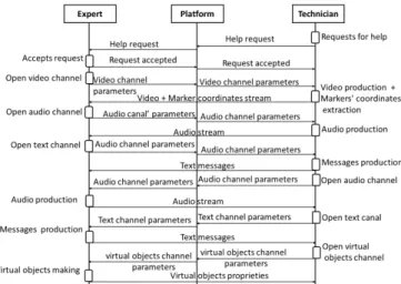
Fig. 2: Establishment of communication between technicians and experts.
As Figure 2 shows, the technician asks first for help from the expert. If the expert accepts his request, each peer (technician and expert stations) opens required channels and send their parameters (IP address and port) to the other peer.
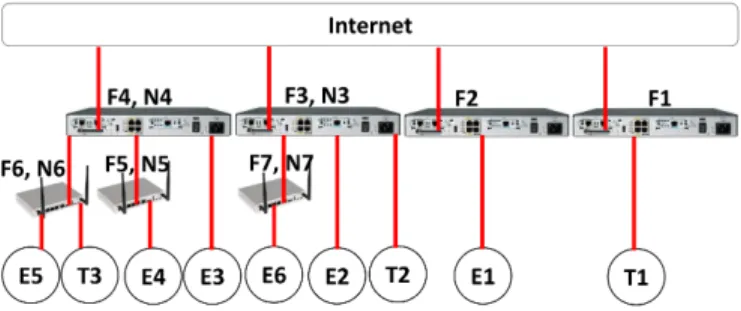
Figure 3 presents possible locations of technicians and experts stations on the network:
• They can have public IP addresses such as T 1 and E1 but located behind different firewalls (T 1 behind F 1, E1 behind F 2);
• One of them can have a public IP address and the other
is being behind NAT and firewall (T 1 is behind F 1, E2 is behind NAT (F 2, N 2));
• Both are connected to the same NAT and firewall that are connected to Internet (T 2 and E2 are both behind the NAT (F 2, N 2) that is connected directly to Internet);
• Each of them is behind a firewall and NAT that are not the same (T 2 is behind the NAT (F 3, N 3), E3 is behind the NAT (F 4, N 4));
• One of them is connected directly (without NAT) to Internet via a firewall and the other is connected to multiple-level NAT (T 1 has a public IP address and is behind F 1, E4 is behind the NAT (F5, N5) that is behind the NAT (F 4, N 4));
• One of them is behind one NAT that is connected directly
to Internet and the other is connected to multiple-level NAT (T 2 is behind the NAT (F 3, N 3) that is connected directly to Internet, E4 is behind the NAT (F 5, N 5) that is behind the NAT (F 4, N 4));
• One peer is connected to NAT that is connected directly to Internet and the other peer is connected to multiple-level NAT that is connected to the same NAT than first peer (E3 is behind the NAT (F 4, N 4), T 3 is behind the NAT (F 6, N 6) that is behind the NAT (F 4, N 4));
• Both peers are connected to multiple-level NAT. They are not behind the same second-level NAT but are con-nected to the same first-level NAT (E4 is behind the second level-NAT (F 5, N 5) that is behind the first-level
Fig. 3: Technicians and experts location inside the network.
NAT (F 4, N 4), T 3 is behind another second-level NAT (F 6, N 6) that is also behind the same first-level NAT (F 4, N 4));
• Both peers are connected to multiple-level NAT and to the same second-level NAT (E5 and T 3 are behind the second-level NAT (F 6, N 6) that is behind the first-level NAT (F 4, N 4));
• Both peers are connected to multiple-level NAT but
nei-ther to the same second-level NAT nor to the same first-level NAT (T 3 is behind the second-first-level NAT (F 6, N 6) which is behind the first-level NAT (F 4, N 4), E6 is behind another second-level NAT (F 7, N 7) that is behind another first-level NAT (F 3, N 3));
The objective is to allow each technician and expert to communicate over the optimal multimedia channels.
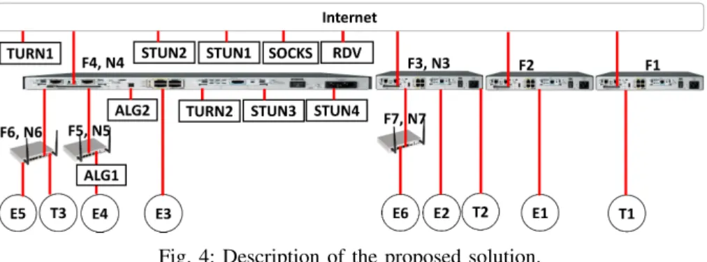
IV. DESCRIPTION OF THE PROPOSED SOLUTION
The proposed solution exploits all techniques listed in the previously section to deal with all possible situations and find the best way to enable communication between technicians and experts. As Figure 4 illustrates, ALG platform is integrated on each peer, STUN and TURN servers are setup on each NAT level, and a rendezvous server (or signaling server) is setup on Internet, called RDV in figure 4. The configuration of each terminal (technician and expert) with IP address and port of each server is done manually. It is noted that ALG platform in the proposed solution should implement all the protocols of UPnP-IGDP, NAT-PMP, PCB in addition to those of classical ALG.
To illustrate how channels establishment is done, we assume that the port mapping on each NAT is as shown in Table I. This table gives information on channels (TCP or UDP) that can be opened by each peers (one channel by technician T i or expert Ei). This configuration will be used as illustrative examples in the rest of this section.
As a general rule, if Peer A wants to receive data from Peer B, it opens a channel and sends its parameters to Peer B. However, if Peer A cannot open the channel because of NAT behavior or firewall configuration, it asks Peer B to initiate communication. If it is impossible to open a direct channel, both peers A and B communicate over the TURN server. Generally, Peer A cannot open a channel when the firewall denies incoming UDP datagrams (datagrams from peers never communicated with Peer A) and incoming TCP connections.
A. Possible technician-expert location cases
Some distinguishable cases that a technician T i and an expert Ei can face aiming to establish channels between them are given in what follows. Other cases are not cited because each of them is similar to the presented ones; for example, (T 1, E3) is similar to (T 1, E2), (T 1, E5) is similar to (T 1, E4), (T 1, E6) is similar to (T 1, E4), (T 2, E1) is similar to (T 1, E2), (T 2, E5) is similar to (T 2, E4), (T 2, E6) is similar to (T 2, E4), (T 3, E1) is similar to (T 1, E4) and finally (T 3, E2) is similar to (T 2, E4).
1) Communication between T 1 and E1: Both peers T 1 and E1 are behind a firewall without NAT and both have a public IP address. First, each of them uses ALG algorithms to check unusable opened ports in the firewall; if no opened port exists, they try to open ports for each channel (TCP or UDP depending on the channel). If ALG algorithms does not work, each peer uses the servers STUN1 and STUN2 to make hole punching:
• Both peers made a TCP and UDP hole punching: each
peer sends the parameters of each channel to the other peer;
• Only one peer made a TCP or UDP hole punching: the
corresponding peer opens channel required by both peers (T 1 and E1) and sends these parameters to the other one. The second peer uses the channel reserved for it to receive data and the other channel to send data;
• Only UDP hole punching is made: if only UDP channels can be opened, both peers use SCTP for reliable channels rather than TCP;
• Both peers could not make neither TCP nor UDP hole punching: in this case, each peer allocates channel in TURN1 server and sends the allocated channels param-eters (within local IP address and port of each channel) to the other peer. The communication between peers and TURN1 can be done over UDP or TCP depending on the channel usage (reliable or not) and the possibility of UDP use.
It is noted that in case of direct communication between the application T 1 and E1 is possible, each of them knows that it has public IP address and port. Thus, it sends only public IP address and port (local IP address and local port) for each channel; in this example, T 1 sends 41.77.180.1 : 1000 and E1 sends 41.77.180.2 : 4000 for the corresponding channel in the example.
2) Communication betweenT 1 and E2: The particularity of this case compared to the previous one is that E2 is behind a NAT. When it makes a hole punching, it retrieves two parameters of each channel: (i) private IP address and private port (in the illustrative example, 10.0.0.2 : 5100), and (ii) public IP address and public port (41.77.180.3 : 5000). First, T 1 tries to reach E2 using the private IP address and private port. In this case, the operation will fail because T 1 and E2 are not connected to the same sub-network; thus, T 1 uses the public IP address and public port.
Fig. 4: Description of the proposed solution.
TABLE I: Configuration of the network illustrated in Figure 4
Peers
First-level NAT Second-level NAT Inside Outside Inside Outside IP address Port IP address Port IP address Port IP address Port T1 41.77.180.1 1000 41.77.180.1 1000 - - - -T2 10.0.0.1 2100 41.77.180.3 2000 - - - -T3 192.168.0.1 3100 10.0.0.5 3200 10.0.0.5 3200 41.77.180.4 3000 E1 41.77.180.2 4000 41.77.180.2 4000 - - - -E2 10.0.0.2 5100 41.77.180.3 5000 - - - -E3 10.0.0.3 7100 41.77.180.4 7000 - - - -E4 192.168.0.2 8100 10.0.0.4 8200 10.0.0.4 8200 41.77.180.4 8000 E5 192.168.0.3 9100 10.0.0.5 9200 10.0.0.5 9200 41.77.180.4 9000 E6 192.168.0.4 10100 10.0.0.6 10200 10.0.0.6 10200 41.77.180.1 10000
3) Communication between T 1 and E4: In this case, E4 is behind a two-level NAT; so, it can use ALG1 or STUN3 and STUN4 to make a hole punching on the first-level NAT (F 5, N 5) and ALG2 or STUN1 and STUN2 to make a hole punching on the second-level NAT (F 4, N 4). Thus, E4 retrieves three parameters for each channel: local IP address and port (192.168.0.2 : 8100) offered by the second-level NAT, IP address and port (10.0.0.4 : 8200) offered by the first-level NAT, and the public IP address and public port (41.77.180.4 : 8000). T 1 tries to reach E4 using its local parameter which will fail because they are not connected the same second-level NAT; therefore, T 1 tries to reach E4 using the first-level NAT parameters that will also fail, and finally T 1 reaches E4 using public parameters.
In case E4 cannot make a hole punching in the second NAT and T 1 cannot make a hole punching on the firewall, the communication will be done over TURN1.
4) Communication betweenT 2 and E2: The peers T 2 and E2 are connected to the same NAT. Each of them sends its local parameters of each channel (10.0.0.1 : 2100 for T 2, 10.0.0.2 : 5100 for E2) and the public parameters (41.77.180.3 : 2000 for T 2, 41.77.180.3 : 5000 for E2) or TURN1 parameters depending on the possibility to make a hole punching. Both peers T 2 and E2 guess that they are con-nected to the same NAT; this is because their local IP addresses are similar. In such a case, they will try to communicate over local parameters because they are connected to the same NAT (F 3, N 3); here, the communication successes and they will not need to use other parameters.
5) Communication between T 2 and E3: As the same situation as in case of T 2 and E2, T 2 and E3 send their local and global (or TURN1) parameters (10.0.0.1 : 2100 and 41.77.180.3 : 2000 for T 2; 10.0.0.3 : 7100 and 41.77.180.4 : 7000 for E3). They try to use local parameters to communicate but they will fail because T 2 and T 3 are not in the same local network even local IP addresses are similar. In such a case, they will make use of global parameters or server TURN1 depending on NATs configuration (F 3, N 3) and (F 4, N 4).
6) Communication between T 2 and E4: This case is sim-ilar to that of T 1 and E4. However in this case, T 2 has two parameters (10.0.0.1 : 2100, 41.77.180.3 : 2000) and E4 has three parameters (192.168.0.2 : 8100, 10.0.0.4 : 8200, 41.77.180.4 : 8000) for each channel. T 2 and E4 do not communicate using local parameters of E4 because they are not similar to that of T 2. However, they try to communicate over local parameters of T 2 because its IP address is similar to that offered by the NAT (F 4, N 4) to E4 ((F 4, N 4) is the first-level NAT of E4); this communication will fail because the two peers T 2 and E4 are not connected to the same NAT. The fact that IP address offered by NAT (F 4, N 4) to E4 and local IP address of T 2 are similar, E4 concludes that they are both connected to the NAT (F 4, N 4). As a consequence, it tries to establish the communication over TURN2 by allocating channels and sending their parameters to T 2; unfortunately, the connection of T 2 to the server TURN2 will also fail. Consequently, they can only communicate over public parameters or server TURN1.
7) Communication betweenT 3 and E3: When T 3 and E3 exchange the parameters of opened channels over the server
RDV, they discover that the local IP address of E3 (10.0.0.3) is similar to that offered to T 3 (10.0.0.5) by NAT (F 4, N 4). If they cannot communicate with each other directly, they will try to use the server TURN2. In this case, they can communicate over TURN2 because they are all connected to the same NAT. Therefore, they do not need to use neither public nor TURN1 parameters.
8) Communication betweenT 3 and E4: Both T 3 and E4 are behind multiple-level NAT. When each of them receives parameters of channels opened by the other one, they conclude that they are connected to the same NAT because their local IP addresses are similar (92.168.0.1 for T 3, 192.168.0.2 for E4). However, they cannot communicate via local parameters because they are not connected to the same NAT (T 3 is connected to (F 6, N 6) and E4 is connected to (F 5, N 5)); additionally, they cannot communicate over the local server TURN because there is no TURN server at this level. Per con-tra, they can communicate over parameters offed by the NAT (F 4, N 4) because they have similar IP addresses (10.0.0.5 for T 3, 10.0.0.4 for E5) and both peers are connected to the same NAT. If the NATs (F 5, N 5) and (F 6, N 6) do not allow hole punching, T 3 and E4 will communicate over TURN2.
9) Communication between T 3 and E5: T 3 and E5 are connected to the same second-level NAT. In such a case, when they receive the parameters of opened channels and try to communicate over local parameters as they have similar IP addresses (192.168.0.1 for T 3, 192.168.0.3 for E5), the com-munication will obviously succeed because both are connected to the same second-level NAT (F 6, N 6) and they will not need to use other parameters.
10) Communication betweenT 3 and E6: Both T 3 and E6 are connected to the multiple-level NAT. However, they are not behind the same first-level NAT (T 3 is behind NAT (F 4, N 4) and E6 is behind NAT (F 3, N 3)). Thus, the only way to communicate is over public parameters (41.77.180.4 : 3000 for T 3, 41.77.180.1 : 10000 for E6) or over the server TURN1.
B. Discussion
It can be noticed that the proposed peer-to-peer communi-cation approach takes a great advantage from the possibility of reconfiguring the network devices (such as NAT and Firewall) and locating the expert and the technician inside the network. Additionally, knowing that our solution is attended to operate in private environments, reconfiguring some network devices is not forbidden.
V. CONCLUSIONS AND FUTURE WORKS
This paper presented the development of a real-time com-munication module between technician and expert stations for an e-maintenance platform using application and signaling servers. This module takes into account the network con-figuration to offer best performances, mainly NAT traversal. Normalized technique for NAT and firewall traversal are listed; some of them require NAT and firewall reconfiguration while others do not. The paper also listed the cases where technicians
and experts can be located on the network. For each case, a procedure is proposed to allow technicians and experts to communicate with each other. It is clear that this solution allows forwarding data over the best path between expert and technician terminals. This is advantageous, especially when both of them are located in the same private network.
Future perspectives will aim to extend this solution for e-health applications while taking into account WHO recom-mendations.
REFERENCES
[1] B. Mechin, Maintenance: concepts et d´efinitions. Ed. Techniques Ing´enieur, 2007.
[2] R. Kour, R. Karim, A. Parida, and U. Kumar, “Applications of radio frequency identification (rfid) technology with emaintenance cloud for railway system,” International Journal of System Assurance Engineering and Management, vol. 5, no. 1, pp. 99–106, 2014.
[3] A. Rachidi, B. Dakkak, A. Talbi, and A. Khatory, “La r´ealit´e augment´ee au service de t´el´emaintenance et de e-maintenance industrielle.” [4] B. Ford, P. Srisuresh, and D. Kegel, “Peer-to-peer communication across
network address translators.” in USENIX Annual Technical Conference, General Track, 2005, pp. 179–192.
[5] “Nat traversal,” https://en.wikipedia.org/wiki/NAT traversal#Techniques, wikipedia.
[6] D. Wing, P. Matthews, R. Mahy, and J. Rosenberg, “Session traversal utilities for nat (stun),” 2008.
[7] M. Leech, M. Ganis, Y. Lee, R. Kuris, D. Koblas, and L. Jones, “Rfc 1928: Socks protocol version 5,” RFC, IETF, March, Tech. Rep., 1996. [8] P. Matthews, R. Mahy, and J. Rosenberg, “Traversal using relays around nat (turn): Relay extensions to session traversal utilities for nat (stun),” 2010.
[9] M. Boucadair, R. Penno, and D. Wing, “Universal plug and play (upnp) internet gateway device-port control protocol interworking function (igd-pcp iwf),” 2013.
[10] S. Cheshire, M. Krochmal, and K. Sekar, “Nat port mapping protocol (nat-pmp),” Work in Progress, 2008.
[11] A. Ripke, J. Quittek, R. Silva, T. Dietz, and R. Winter, “Port control protocol (pcp) third-party id option,” 2016.
[12] P. Srisuresh and M. Holdrege, “Ip network address translator (nat) terminology and considerations,” 1999.
[13] J. Rosenberg and C. Holmberg, “Interactive connectivity establishment (ice): A protocol for network address translator (nat) traversal,” 2018. [14] A. Bergkvist, D. C. Burnett, C. Jennings, A. Narayanan, and B. Aboba,
“Webrtc 1.0: Real-time communication between browsers,” Working draft, W3C, vol. 91, 2012.
[15] S. Benbelkacem, N. Zenati-Henda, F. Zerarga, A. Bellarbi, M. Bel-hocine, S. Malek, and M. Tadjine, “Augmented reality platform for col-laborative e-maintenance systems,” in Augmented reality-some emerging application areas. IntechOpen, 2011.
[16] M. Fritscher, F. Sittner, D. Aschenbrenner, M. Krauß, and K. Schilling, “The adaptive management and security system for maintenance and teleoperation of industrial robots,” IFAC-PapersOnLine, vol. 49, no. 30, pp. 6–11, 2016.
[17] S. Benbelkacem, N. Zenati-Henda, H. Belghit, A. Bellarbi, and S. Ot-mane, “Extended web services for remote collaborative manipulation in distributed augmented reality,” in 2015 3rd International Conference on Control, Engineering & Information Technology (CEIT). IEEE, 2015, pp. 1–5.
[18] D. Mourtzis, A. Vlachou, and V. Zogopoulos, “Cloud-based augmented reality remote maintenance through shop-floor monitoring: a product-service system approach,” Journal of Manufacturing Science and Engi-neering, vol. 139, no. 6, p. 061011, 2017.
[19] S. Bottecchia, J.-M. Cieutat, and J.-P. Jessel, “T.A.C: Augmented Reality System for Collaborative Tele-Assistance in the Field of Maintenance through Internet.” in AH’2010 (Augmented Human), Apr. 2010, pp. 1–7, iSBN: 978-1-60558-825-4. [Online]. Available: https://hal.archives-ouvertes.fr/hal-00585435
[20] “Live networks, inc,” http://www.live555.com/, Live Networks, Inc. [21] D. Fang, H. Xu, X. Yang, and M. Bian, “An augmented reality-based
method for remote collaborative real-time assistance: from a system perspective,” Mobile Networks and Applications, pp. 1–14, 2019.