With Camera-Based Motion Compensation
The MIT Faculty has made this article openly available. Please share
how this access benefits you. Your story matters.
Citation
Ranger, Bryan J., et al., "3D Ultrasound Imaging of Residual Limbs
With Camera-Based Motion Compensation." IEEE Transactions
on Neural Systems and Rehabilitation Engineering 27, 2 (February
2019): p. 207-17 doi 10.1109/TNSRE.2019.2894159 ©2019 Author(s)
As Published
10.1109/TNSRE.2019.2894159
Publisher
Institute of Electrical and Electronics Engineers (IEEE)
Version
Author's final manuscript
Citable link
https://hdl.handle.net/1721.1/124533
Terms of Use
Creative Commons Attribution-Noncommercial-Share Alike
GENERIC COLORIZED JOURNAL, VOL. XX, NO. XX, XXXX 2017 1
3D ultrasound imaging of residual limbs with camera-based motion
compensation
Bryan J. Ranger,
Member, IEEE, Micha Feigin,
Member, IEEE, Xiang Zhang,
Member, IEEE, Kevin M.
Moerman,
Member, IEEE, Hugh Herr,
Member, IEEE, Brian W. Anthony,
Member, IEEEAbstract—Ultrasound is a cost-effective, readily available, and non-ionizing modality for musculoskeletal imaging. Though some research groups have pursued methods that involve submerging the transducer and imaged body segment into a water bath, many limitations remain in regards to acquiring an unloaded volumetric image of an entire human limb in a fast, safe and adequately accurate manner. A 3D dataset of a limb is useful in several rehabilitative applications including biomechanical modeling of soft tissue, prosthetic socket design, monitoring muscle condition and disease progression, bone health, and orthopedic surgery. This paper builds on previous work from our group and presents the design, prototyping, and preliminary testing of a novel multi-modal imaging system for rapidly acquiring volumetric ultrasound imagery of human limbs, with a particular focus on residual limbs for improved prosthesis design. Our system employs a mecha-nized water tank setup to scan a limb with a clinical ultrasound transducer, and 3D optical imagery to track motion during a scan. The iterative closest point algorithm is utilized to compensate for motion and stitch the images into a final dataset. The results show preliminary 2D and 3D imaging of both a tissue-mimicking phantom and residual limbs. A volumetric error compares the ultrasound image data obtained to a previous MRI method. The results indicate potential for future clinical implementation. Con-cepts presented in this work could reasonably transfer to other imaging applications such as acoustic tomography, where motion artifact may distort image reconstruction.
Index Terms—Biomedical imaging, musculoskeletal, prosthetic socket design, ultrasound
I. INTRODUCTION
It is reported that 57% of persons with transtibial amputation suffer from moderate to severe pain when wearing a prosthetic limb [1]. Improper fit of the prosthetic socket, the cup-like interface connecting residual limb to the remainder of the prosthesis, can lead to several pain-causing pathologies including neuromas, inflammation, soft tis-sue calcifications, and pressure sores [2]. A person with amputation may choose not to wear their prosthesis if it is not comfortable; thus, it plays a critical role in physical rehabilitation and subsequent future health outcomes. The current standard for prosthetic socket fabrication is plaster casting, a mostly subjective process performed by a prosthetist. Though this artisanal method can be effective in some instances, it is expensive, time consuming, and often requires several iterations in order to achieve a desirable fit. A quantitative, reproducible, and data-driven procedure for socket creation could have substantial clinical impact [3].
For a person with amputation using a prosthetic lower limb, both static and dynamic loads are maintained by transferring forces
Manuscript received MONTH DAY, YEAR; revised MONTH DAY, YEAR; accepted MONTH DAY, YEAR.
B.J. Ranger, M. Feigin, X. Zhang, and B.W. Anthony are with the Institute for Medical Engineering and Science, 45 Carleton Street, E25-317, Massachusetts Institute of Technology, Cambridge, MA 02139 USA (e-mail: banthony@mit.edu).
B.J. Ranger, K.M. Moerman, and H. Herr are with the MIT Media Lab, 75 Amherst Street, E14-274, Massachusetts Institute of Technology, Cambridge, MA 02139 USA.
M. Feigin, X. Zhang, and B.W. Anthony are with the Department of Mechanical Engineering, 127 Massachusetts Avenue, 35-017, Mas-sachusetts Institute of Technology, Cambridge, MA 02139 USA.
from the socket to the limb soft tissue. Therefore, biomechanical understanding of the tissues throughout the socket-limb interface is essential when trying to derive a comfortable socket design. There have been several advances in scanning of the residual limb and ma-nipulating this data as input to computer-aided design/manufacturing (CAD/CAM) of prosthetic sockets [4]–[8]. Nevertheless, most studies either (a) focus only on the external shape of the limb and do not take into account quantified internal tissue distributions or compliance data which is necessary for analyzing and simulating accurate loading conditions, or (b) use expensive scanning tools that are only available in specialized facilities. An attractive alternative that may address these limitations is musculoskeletal (MSK) ultrasound (US) imaging [9].
There have been many recent developments in applications of US imaging to the MSK field due to its inherent advantages of real-time performance, high tissue resolution, relative speed and accessibility as compared to other imaging modalities [10]. For example, computed tomography (CT) exposes the patient to ionizing radiation, while magnetic resonance imaging (MRI) is not always possible, particularly in cases where the patient may have medical implants or combat injuries where metal shrapnel may be present. Alternatively, 3D US is a low-cost and widely available option for obtaining volumetric and diagnostically useful images particularly in rehabilitation applications [11]. No intensive training or radiation protection is necessary for its use, and its hardware is portable, thus allowing for use at the bedside and making it more accessible in tertiary or more resource-constrained facilities.
In clinical applications of MSK imaging, it is often sufficient to achieve a reconstructed volume that does not contain the complete anatomy of the imaged body segment (e.g., diagnosing a local pathology or guiding an intervention such as soft tissue biopsy may only require a regional field of view) [12]. However, of particular interest in this work is reconstructing an image volume of an entire limb that could subsequently be used in soft tissue modelling, load simulation, and computational mechanical interface design (e.g., CAD of prosthetic sockets), both of which require complete 3D anatomical information. For example, acquiring external limb and bone shape from medical imaging data has been shown to create computationally designed prosthetic interfaces [5]. To acquire a 3D US scan of a limb, several approaches have been pursued. One conceivable solution involves covering the imaged body segment in gel, scanning up and down around the body segment, and stitching the collected images into a volume [13]. However, since there is direct contact between the transducer and body surface, soft tissues are deformed; if tissue deformation is not appropriately accounted for, it can lead to an inaccurate portrayal and biomechanical characterization of the anatomy. Further, contact during scanning can cause motion of the limb, thereby generating yet another source of error [14].
To address these challenges, multiple research groups have pursued methods that involve submerging the transducer and imaged body segment into a water bath to achieve unloaded 3D US imagery; such approaches were built on concepts developed for acoustic tomography, which have been clinically applied recently to breast imaging [15]–[18]. Douglas et al. [9] provide a thorough review of
these technical efforts as it relates to residual limb imaging, which have shown varying levels of success. Of particular relevance were research projects pursued by groups at Wright State University [19]– [21] and Sandia National Labs [22]. Each group independently devel-oped US B-mode systems that construct three-dimensional images of residual limbs. However, to the authors knowledge, due to limitations neither of the teams advanced to the point where their systems are routinely used in clinical practice. As highlighted in Douglas et al. [9], some of the limiting factors of these previous studies include: (i) the mechanical setup of the scan proved cumbersome, (ii) limb motion degraded image resolution and it was difficult to compensate for, and (iii) final results did not allow for accurate differentiation between tissue types. Follow-up studies used image feature-based registration for motion compensation and spatial compounding, but the results did not allow for rapid volumetric imaging [23].
This paper presents a multi-modal imaging system that is able to acquire a volumetric image by scanning the limb with the transducer array oriented vertically, effectively collecting an array of single element images circumferentially around the limb to capture an entire volume. In this arrangement, there is no spatially overlapping image frames so image-based motion compensation is not possible. To address this, we incorporate a 3D camera, mounted in the bottom of the tank, to track motion of the body segment and appropriately position the imagery in space. The work presented here builds on studies previously completed in our group that had not yet focused on completing a full 3D image dataset of a limb [17], [24], [25].
In this study, we first show 2D image results (ultrasound trans-ducer oriented horizontally) of both a tissue-mimicking phantom and residual limbs thereby demonstrating that motion compensation is effective at creating tomographic slices. We conclude by showing 3D results (ultrasound transducer oriented vertically) and demonstrate that external limb and bone shape may be obtained by segmenting the volumetric image data. External limb and bone shape may be incorporated directly into automated prosthetic design methods, as described in Moerman et al. [5]. Though this work focuses on imaging human residual limbs, the concepts could reasonably transfer to other imaging applications such as acoustic tomography, where volumetric imaging may provide additional clinical insight, and where motion artifacts have been shown to distort image reconstruction [18]. Furthermore, our results hold significant promise for expanding research in other MSK US clinical applications, such as monitor-ing muscular dystrophy progression, bone density monitormonitor-ing, and orthopedic surgery planning.
II. MATERIALS ANDMETHODS
In this section, we present: (i) the mechanical design of the ultrasound scanning system, (ii) an external motion compensation framework utilizing 3D optical imagery with no fiducial markers to stitch images together into a volume, (iii) our calibration scheme, (iv) the human subject scanning protocol, (v) 2D ultrasound image collection with comparison to MRI, and (vi) 3D ultrasound image collection with comparison to MRI. All data post-processing was completed using MATLAB (R2017a).
A. System Overview and Mechanical Design
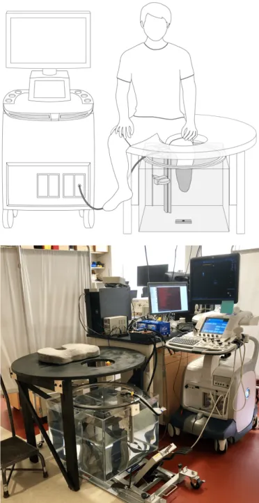
Similar to devices developed by He et al. [19]–[21], Morimoto et al. [22], and more recently Zhang et al. [26], [27], we constructed a mechanical system thereby allowing for controlled circumferential US scanning of an unloaded limb inside of a water tank. A schematic of the overall system with a depiction of patient placement during scanning is shown in Fig. 1. To complete a scan, a subject placed their limb in the tank, and the US transducer (LOGIQ E9, 9L Transducer,
Fig. 1. (Top) Schematic of the prototype ultrasound system showing limb placement during a scan. The ultrasound transducer is mounted to a ring bearing that allows for circumferential rotation around the imaged body segment (shown here as a residual limb). A 3D camera is mounted below the tank, facing upward, and is used to track motion of the limb during scanning. (Bottom) Photo of the scanning setup.
General Electric, Niskayuna, NY) rotated circumferentially around the limb collecting images at set angular increments. A combination 3D, IR and color camera (SR300 RealSense Camera, Intel Corp., Santa Clara, CA) was secured below the tank, pointed upward, to track limb position during the scan by imaging the 3D surface geometry of the limb. The camera produced images at a standard resolution of 640x480.
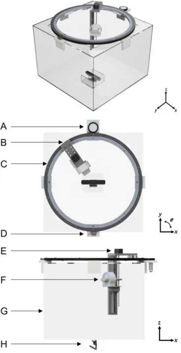
CAD renderings depicting the mechanical design of the ultrasound imaging system is shown in Fig. 2. The prototype was constructed from a 24×24×18 in clear acrylic tank with a 600 mm-diameter ring bearing mounted on top. A custom 3D-printed mount secures
RANGER et al.: IEEE TRANSACTIONS ON NEURAL SYSTEMS AND REHABILITATION ENGINEERING 3
Fig. 2. CAD renderings showing angular, top-view and side-view of the ultrasound tank system. (A) Friction pinion with DC motor to drive rotation of ring bearing. (B) Mount that allows for radial adjustment of the transducer to account for different limb sizes. (C) Ring bearing. (D) Magnetic encoder. (E) Stepper motor to control motion in the z direction. (F) Ultrasound transducer housed in custom bracket. (G) Acrylic tank. (H) 3D camera.
the ultrasound transducer to the z-axis linear rail on the ring bearing; the 3D printed mount was designed to allow transducer rotations relative to the horizontal at pre-determined angles.
Circumferential rotation of the ring bearing was driven by a DC motor (2826 100:1 metal gear motor, Pololu Electonics, Las Vegas, NV) with a custom friction pinion. A NEMA-17 stepper motor (Schneider Electric, Cambridge, MA) enabled controlled vertical z-translation of the ultrasound transducer. Additionally, the radial position of the ultrasound transducer can be adjusted manually at set circumferential positions, enabling adaption of the scanning apparatus for a range of limb sizes.
Fig. 3. System Diagram of ultrasound imaging system. An Arduino is used to control the stepper and DC motor, and to ensure that data collected from the 3D camera and encoder are synchronized with the ultrasound imaging system.
The angular position (θn) of the transducer was tracked using a
lin-ear magnetic encoder system (LM10, Renishaw Inc., Gloucestershire, UK). The encoder consisted of an adhesive-backed magnetic scale taped around the circumference of the ring bearing, and a non-contact magnetic encoder head to detect quadrature encoding on the magnetic scale. The angular position (θn) of the transducer was calculated via
quadrature decoding and basic geometry on the controller.
A diagram depicting the electronic control system is shown in Fig. 3. An Arduino UNO microcontroller read trigger signals from the GE ultrasound system and calculated the angular position data from the magnetic encoder. It also controlled the motors, image trigger of the 3D camera, and time synchronized data collections to the PC. B. 3D Camera-based Motion Compensation
Motion presents a significant challenge for limb imaging in an US water tank setup for several key reasons. First, acquiring unloaded limb geometry, which is important for applications to prosthetic socket design as well as for accurate biomechanical tissue modeling, necessitates that the limb be in an unperturbed state. Therefore, a harness or mount that makes contact with the imaged body segment may not be used to provide structural support and stabilize limb motion during a scan. In addition, for US images collected circumferentially around a limb, acoustically reflective surfaces (e.g., bone) change appearance depending on the orientation of the imaging array. Therefore, traditional image registration and stitching based on image features (e.g., RANSAC) is not always effective [27]. To solve this, we utilized a structured light-based 3D camera to track residual limb surface structure during a scan.
Two-stage tracking is performed on the 3D camera output: first, each camera frame was referenced to the first frame in the circum-ferential scan, and then the first frame was referenced to the first frame of each scan in the series. This approach results in better per-scan alignment while allowing (i) creation of an aggregate volume using multiple scans, and (ii) acquisition of multiple scans of the same section, which may be combined to produce a higher resolution volume. Since the 3D camera has a different frame rate than the ultrasound system, and no input/output trigger, we time stamped each received image. Based on the limb tracking, we generated a time dependent position vector, from which we interpolated the ultrasound frame position.
To perform limb tracking, we use the point cloud 3D structure produced by the 3D camera, where each 3D frame, with index n,
provides a set Pn consisting of m points: Pn= n p1n, p2n, pmn o ∈ R3 (1)
where pin represents the position vector of the i-th point of time step
index n. In our setup, since the subject was seated and asked to fully extend their limb (i.e, knee was not bent) into the scanning tank, we assumed that rotation at the knee and out-of-plane motion was negligible; therefore, motion was approximated as translation-only. An initial estimation of the limb displacement was obtained from the location of the overall mean of the point cloud compared to the mean value of the reference frame point cloud.
We then applied the iterative closest point (ICP) algorithm to improve alignment between the point clouds. For this study, we utilized the generalized ICP algorithm (GICP) developed by Segal et al. [29], as implemented in the Point Cloud Library (pointclouds.org). The ICP algorithm computed the affine transformation between two point clouds that minimized the Euclidean distance between the clouds. There are several approaches to using the ICP algorithm, but in its simplest formulation, the ICP algorithm looks at point-pair matches between the point clouds and minimizes the mean of the sum of squared distances between these point pairs. This is a greedy optimization-based algorithm that significantly benefits from a good initial guess (in this case, the mean approximation).
Assuming translation-only motion, since the subject held their limb straight without bending at the knee, we ignored the rotation/scaling factors produced by the ICP algorithm and utilized the translation offset only (∆xn, ∆yn, ∆zn). This is another factor that benefited
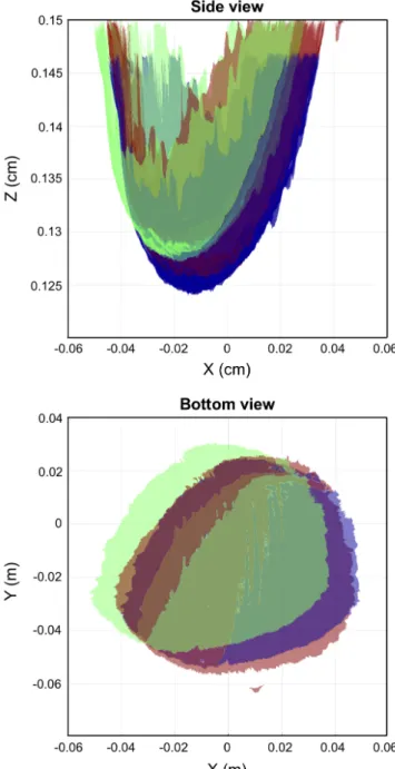
from the mean approximation, as with non-centered objects, there can be an ambiguity between rotational and translational motion. An example of the 3D surfaces acquired from the 3D camera are shown in Fig. 4, projected on to the x-z and x-y plane. Two of the surfaces (red and green) were acquired from the 3D camera at two different time points during the scan. The second surface (green) is shifted to its motion compensated position (blue).
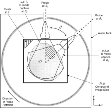
As depicted in Fig. 5, to create a 2D ultrasound image, U (i, j), the ∆xn, ∆yn, ∆zn positions as calculated by the ICP algorithm
are used to spatially place the individual ultrasound images (collected at each θn) in the compound image space. Each individual B-mode
capture un(i, j), which has pixel size of 0.234 × 1.593 mm, is
rotated in-plane based on its associated θn. Images were stitched
together into the 2D image slice U (i, j) by choosing the maximum value at each overlapping pixel, where (i, j) are the grayscale values in the images. Maximum values were chosen for this study instead of mean or median values because for this particular application to computational prosthetic socket design, we were focused on acquiring bone and skin surfaces. In ultrasound imagery collected in a water tank system, reflective surfaces (e.g., bone and skin) present as elevated pixel values. In order to retain this information in the final imagery, rather than blur out these features, a maximum value was chosen.
To create a 3D image of the limb, ultrasound data collected from the scan in which the transducer was in the longitudinal position were pieced into a volume and interpolated. In this case, there was no overlapping imagery, so placement of the images in space was accomplished using only 3D camera data, as described above. The image volume can then be re-sliced into a 2D image for direct comparison to the 2D images created above.
C. System Calibration
In order to reconstruct a tomographic image, we positioned each ultrasound sample in 3D space. This entailed two challenges: (i) distinguishing the physical position of the transducer in each frame,
Fig. 4. Motion compensation using camera-based registration and ICP. Two example 3D surfaces (red and green) that were collected at two different time points during the scan are shown projected on the x-z plane (top) and x-y plane (bottom). The second surface (green) was translated by the ICP result to the spatial location (blue) that matches the first reference surface. This demonstrates that our camera-based ICP method can track motion during the scan.
and (ii) correcting for relative subject motion with respect to the transducer. This translated into two calibration tasks. First, we calibrated the ultrasound system parameters; this included rotation radius and transducer offset with respect to the center line. Second, we translated camera tracking coordinates to the ultrasound image space (i.e., translation scaling and relative rotation). To this end, we constructed an image of a calibration phantom, with the requirements of being able to track the phantom in both ultrasound and camera image spaces. The phantom was custom-made into a cylinder (10 cm diameter) and composed of a mixture of copolymer, mineral oil, and graphite powder (refer to [28] for detailed steps of fabricating a tissue
RANGER et al.: IEEE TRANSACTIONS ON NEURAL SYSTEMS AND REHABILITATION ENGINEERING 5
Fig. 5. Coordinate frame used for image registration and stitching process for creation of a 2D image slice. U (i, j) represents the 2D compound image slice created by combining each individual B-mode capture un(i, j). Grayscale pixel values are indexed as (i, j). The
ultrasound transducer rotates around the imaged body segment in the clockwise direction. Images and point clouds are acquired simultane-ously at recorded θn.
mimicking phantom in this manner). Our calibration device (Fig. 6) consisted of a PVC rod mounted to a linear rail and connected to the phantom. A fiducial marker, in this case half of a standard ping pong ball, was mounted to the bottom of the rod for camera tracking.
1) Ultrasound System Calibration: To calibrate the ultrasound system scanning hardware, we performed a full tomographic scan with the transducer oriented in a transverse (i.e., horizontal) position to acquire in-plane images. Since the scan follows a fixed circular path, the distance and relative orientation of the center of rotation to the transducer face was fixed. Thus, all images in the scan can be rotated and translated in-plane (Fig. 6B) so that they were aligned into a joint coordinate system according to the following transformation:
b
p = Rp + b (2)
where R was the rotation matrix and b a translation vector, the center point was the stationary point of this transformation. The center point of rotationbr, in the ultrasound image coordinate system, was given by:
b
r = Rr + b (3)
r = (1 − R)−1b (4)
All images collected in the calibration scan were aligned in pairs to each other using the algorithm described in Feigin et al. [30]. We then applied the above formula to recover r for each image pair, and finally averaged all the results after outlier removal and computed the transducer position in ultrasound image space (in pixels) with respect to the center of rotation. Outliers were removed by calculating the median point and filtering out points that were outside of 50% of the closest points.
2) Camera Calibration: To transform from 3D camera image space into ultrasound image space, we recovered two parameters: (i) rotation and (ii) scaling. As all frames are referenced to the same
reference frame, the transformation is invariant to the joint translation. For this purpose, it was possible to take an image with both ultrasound and 3D camera at two different arbitrary positions (with in-plane motion between them) and having a translation vector (two points) in each domain uniquely defines both scaling and rotation. In practice, we took a full scan of the phantom at two different positions and averaged the transforms over all matching image pairs in order to calibrate the system.
D. Scanning Protocol
Subjects were recruited following a procedure approved by the MIT Committee on the Use of Humans as Experimental Subjects (COUHES). Two male transtibial amputee subjects were recruited for this study: one bilateral and one unilateral, allowing for a total of three limbs to be imaged.
To avoid sound speed gradients, the imaging tank was filled with deionized water that was approximately body temperature. To complete the ultrasound scan, the subject was seated above the imaging tank and asked to submerge their limb into the water (Fig. 1). Once the subject was comfortably situated, the ultrasound transducer completed a 360-deg pass circumferentially around the limb; during this period, the ultrasound transducer and 3D camera collected data simultaneously. One 360-deg pass took approximately 15 s to complete. For each subject, the following scans were collected: (1) 3 separate image slices in which the ultrasound transducer is situated in the transverse (horizontal) orientation and (2) a full volume scan in which the transducer was placed in the longitudinal (vertical) orientation.
MRI was performed for comparison to the ultrasound images produced from our system. To complete the scan, the subject was situated prone and feet-first inside a 3 Tesla MRI scanner (Siemens Magnetom Tim Trio 3T, Siemens Medical Systems, Erlangen, Ger-many). All imaging was performed with a RF body coil wrapped around the limb; no contact was made between the coil and limb so as to prevent tissue deformation. A T1 MPRAGE sequence was used (for patient 1: T R = 2530, T E = 3.9, acquisition matrix 176 × 256, 176 slices, voxel size 1.00 × 1.00 × 1.00 mm; for patient 2: T R = 633, T E = 8.7, acquisition matrix 320 × 320, 90 slices, voxel size 1.00 × 1.00 × 1.00 mm) for image data acquisition. Slight differences in the sequences between the two patients were due to real-time optimizations by the radiographer for the given scan. E. 2D Image Analysis and Comparison to MRI
To compare the ultrasound to MRI images, qualitative and quantita-tive evaluations were performed. Data outside the skin contours (e.g. water visible in the ultrasound scans) was excluded and cut out from the views for this comparison. For qualitative assessment, similarities between anatomical structures such as muscle architecture and bone were analyzed. To quantitatively compare between 2D image sets, we utilized ImageJ (v1.46r) to manually select a region of interest (ROI) around both the skin and tibia for all 9 slices that we collected (Fig. 8). A pixel count was performed for each region of interest and used to calculate the area (in mm2) of the tibia and bone. A percent error was calculated to analyze differences between MRI and ultrasound images. Future studies will involve scanning a larger cohort of patients and include a more detailed quantitative shape comparison.
F. 3D Image Analysis and Comparison to MRI
To evaluate the ability of our ultrasound system to accurately gen-erate limb geometry, we compared skin and bone shapes segmented
TABLE I
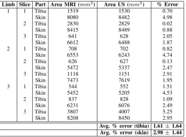
2DSIZE COMPARISON BETWEENMRIANDULTRASOUND Limb Slice Part Area MRI (mm2) Area US (mm2) % Error
1 1 Tibia 1519 1530 0.70 Skin 8080 8482 4.98 2 Tibia 2830 2829 0.02 Skin 8415 8489 0.88 3 Tibia 641 628 2.05 Skin 6612 6488 1.87 2 1 Tibia 708 702 0.82 Skin 6553 6243 4.74 2 Tibia 626 627 0.13 Skin 5472 5337 2.47 3 Tibia 1118 1151 2.91 Skin 7473 7619 1.95 3 1 Tibia 544 552 1.51 Skin 5452 5205 4.53 2 Tibia 837 828 1.09 Skin 6231 6076 2.49 3 Tibia 3807 4007 5.25 Skin 8208 8450 2.95
Avg. % error (tibia) 1.61 ± 1.64 Avg. % error (skin) 2.98 ± 1.44
from the ultrasound data to its respective MRI. For this purpose, the GIBBON MATLAB Toolbox [31] was used to: (i) view the image data in 3D space, (ii) semi-automatically create contours of the skin and bone surfaces from both MRI and US volume data (GIBBON imx function), and (iii) quantitatively compare surface shapes by evaluating closest point-to-point distances.
III. RESULTS
Fig. 6 presents the results of the 10-cm-diameter tissue-mimicking cylindrical gel phantom, created to model a residual limb. As shown in Fig. 6A and Fig. 6C, inserted inside of the phantom is a 3-cm-diameter hollow PVC pipe, which acts as a reflective surface to mimic bone. In Fig. 6D, the reconstructed ultrasound image accurately represents the expected cross-section (Fig. 6C).
Results to demonstrate our 3D camera approach for motion com-pensation are shown in Fig. 7. In Fig. 7A, two ultrasound images (red and green) that were collected at distinct circumferential positions of the same limb are shown overlaid; there is clear motion between images as evidenced by the discontinuity seen in the skin boundary (shown by the arrow). In Fig. 7B, the same images are shown, but now are shifted into the correct spatial position. Fig. 7C and Fig. 7D show the corresponding full ultrasound image of the same subject, both before motion compensation and after motion compensation. This demonstrates that motion correction with the 3D camera is effective and does not require further registration using image features.
2D tomographic image results, in which imagery was collected with the transducer oriented in the transverse direction, are shown in Fig. 8 for the two research subjects. Fig. 8A and Fig. 8C are MRI images, while Fig. 8B and Fig. 8D are the two corresponding ultrasound image slices. The tibia and fibula are clearly seen in both the MRI and ultrasound data sets and have similar morphology, and general muscle structures including the gastrocnemius and tibialis anterior are comparable.
Quantitative results comparing the size of bones and limb in 2D images are shown in Table 1. The average percent error of tibia size between all three limbs was 1.61±1.64, and the average percent error of limb size as measured by the skin boundary was 2.98 ± 1.44.
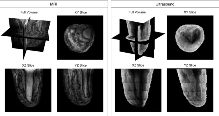
A volume result of a residual limb, in which ultrasound imagery was collected with the transducer oriented in the longitudinal direc-tion, is shown in Fig. 9. The vertical array did not cover the entirety of the imaged body segment, therefore five acquisitions at set z increments were collected and then stitched together. Images were
Fig. 6. Phantom with calibration device. (A) Calibration device to simulate controlled leg motion: 1. Linear rail, 2. PVC pipe, 3. Tissue-mimicking gel phantom, 4. Spherical fiducial marker. (B) Schematic depicting calibration procedure. (C) Cross-sectional rendering of calibra-tion device: the outer gray area is the tissue-mimicking phantom, and the inner black area is the PVC pipe meant to mimic a reflective boundary like that that of bone. (D) Example of a reconstructed ultrasound image of phantom.
pieced together into the volume using 3D camera tracking without overlapping imagery. The full volume with cross-sectional views is shown in the top left. 2D cross-sectional slices of the image volume are also shown in the XY, XZ, and YZ planes. Limb and bone shape, as well as other anatomical soft tissue structures, are discernible. Though some penetration issues are evident in the XY slice for US, it is evident that a 3D-camera-based approach that allows for rapid
RANGER et al.: IEEE TRANSACTIONS ON NEURAL SYSTEMS AND REHABILITATION ENGINEERING 7
Fig. 7. Demonstration of motion compensation based on 3D camera tracking. (A) Two overlaid ultrasound images, shown in red and green, collected at different circumferential positions. There is clear motion present in the scan, as evidenced by the discontinuity in the skin surface near the top shown with the arrow. (B) The same images from (A) but are motion-compensated using the 3D camera data. Anatomy between the two images are now correctly matched. (C) An example ultrasound reconstruction with no motion compensation. (D) An example ultrasound reconstruction with motion compensation.
TABLE II
3DSHAPE COMPARISON BETWEENMRIANDULTRASOUND
Part
Avg. difference between MRI and US (mm)
Skin
2.75 ± 4.11
Tibia
2.38 ± 5.18
Fibula
2.25 ± 2.72
volumetric imaging is feasible for this application.
We conclude by demonstrating results of surfaces of the skin, tibia, and fibula that were segmented from US and MRI volume imagery for one limb. User-selected contours are shown in Fig. 10A, with the resulting 3D surfaces from US and MRI shown in Fig. 10B and Fig. 10C. Figs. 10D-F show difference maps that depict shape differences between skin, tibia, and fibula, respectively. Average differences with associated standard deviations are recorded in Table 2; results for all are between 2-3 mm.
IV. DISCUSSION
In this paper, we present a novel ultrasound imaging system along with associated preliminary results of a tissue-mimicking phantom and residual limbs. Our multi-modal imaging approach incorporates both a clinical US transducer and 3D optical imagery for motion compensation. The integrated imaging system produces fast, safe and adequately accurate 3D ultrasound imagery of the salient volumetric features of a residual limb. One rotation of the transducer around the limb takes approximately 15 seconds; thus, the entire volume of the limb may be scanned in approximately 2-3 minutes depending on the size of the limb. Compared to a standard MRI scan which can take approximately 10-15 minutes, this rapid collection of 3D
Fig. 8. Ultrasound 2D imaging results showing a representative slice for two research subjects. (A) and (C) are MRI images, while (B) and (D) are the two corresponding ultrasound image slices created when the ultrasound transducer. Water was removed from the ultrasound images for a more straightforward comparison. Using ImageJ, in (A) and (B) the tibia bone is outlined and in (C) and (D) the skin boundary is outlined a pixel count of these areas for each of the research subjects is presented in Table 1 for comparison.
imagery addresses several key limitations outlined in the literature for accurate and quick lower extremity US imaging.
Computed tomography (CT) imaging is, at present, the method of choice for the generation of subject-specific finite-element models of bone [32]. It is, however, not ideal for multi-scan applications because CT exposes the subject to ionizing radiation, and thus not ideal for applications that may require multiple scans. Though MRI has its own limitations related to cost and requirements for a specialized imaging facility, it was chosen for our preliminary comparative studies here since it has been effective for the purposes of modeling the residuum for prosthetic socket design and does not present the same radiation concerns [5], [33], [34].
When comparing the 2D ultrasound image results (Fig. 8) to corresponding MRI images, similar anatomical structures, including shape of the tibia and fibula bones and general muscle architecture of the gastrocnemius and tibialis anterior, are noted. Differences in overall limb morphology are expected since imagery was collected while the patient is situated in different orientations: during an MRI scan the subject is situated in the prone position with leg elevated, while during the ultrasound scan the subject is situated upright with their limb extended downward and submerged in water. Imagery may also be different since residual limb volume is expected to fluctuate significantly, even throughout the day [35]. As reported in Sanders et al.[36], residual limb cross-sectional area changes over the course of a day can vary from -2.4% to +2.2%. Therefore, the percent error values as reported in Table 1 are sufficiently low when comparing the tibia and the skin across our sample set. This validates, in part, that our 2D imagery is producing accurate representations of limb anatomy. Importantly, these results demonstrate the ability of our motion compensation framework to produce accurate images, and opens the door for 3D imaging without using image features or
Fig. 9. Volume ultrasound imaging results (left) for one amputee subject with associated MRI (right). The top left image of each shows the image volume along with slice planes. XY, XZ, and YZ slices are shown to demonstrate feasibility of acquiring volumetric data. As shown, using camera-based motion compensation, acquisition sweeps can be stitched together in 3D space to produce continuous skin and bone boundaries.
Fig. 10. (A) Surface contours created of the skin (blue), tibia (green), and fibular (red) from the 3D ultrasound data. (B) Resulting surfaces from US created from the contours shown in (A). (C) Resulting surfaces from MRI, created in the same manner as the US surfaces. (D) 3D difference map showing differences (mm) between MRI and US skin surfaces. (E) 3D difference map showing differences (mm) between MRI and US tibia surfaces. (F) 3D difference map showing differences (mm) between MRI and US fibula surfaces. Average differences for (D), (E), and (F) are recorded in Table 2.
RANGER et al.: IEEE TRANSACTIONS ON NEURAL SYSTEMS AND REHABILITATION ENGINEERING 9
fiducial markers.
Re-sliced images of the limb volume, as shown in Fig. 9, demon-strate that imaging with the longitudinal transducer orientation in combination with camera-based motion compensation is feasible for rapidly acquiring 3D imagery of a limb. Qualitatively, overall morphology of skin, muscles and bones are comparable to MRI. Despite very encouraging results, there are noteworthy areas for improvement; for example, there is noticeable shadowing behind the tibia and fibula bones in the transverse slice. This may be re-mediated in the future by imaging with a higher penetration depth or lower frequency.
Anatomical structures, including skin and bone, can be segmented from the imaging data. Fig. 10, along with Table 2, provide the spatial differences between skin, tibia, and fibula. The average differences fall within approximately 2-3 mm for each. Given that the isotropic voxel size for our MRI images is 1 mm, that previous studies have shown successful MRI segmentations for prosthesis design with voxel depth of 2 mm [37], and that our MRI sequence was not optimized for musculoskeletal scanning, the differences in size are reasonable for our preliminary results and further demonstrates that our methods produce adequately accurate volumetric imagery of the residual limb useful for prosthesis design.
In addition, our group has considered software-based techniques for combining ultrasound images that do not rely on the 3D camera. Specifically, a method by Feigin et al. [29] utilizes a novel statistical consensus matching framework to register images collected in the same horizontal plane into a compound 2D image. In a forthcoming journal publication that expands on the same topic with more im-age results, we show that using this framework outperforms other common registration methods. In developing this framework, the focus was primarily on creating a 2D image slice of the limb that could demonstrate comparable morphology to other common imaging modalities. Thus, it focuses only on images collected in the same horizontal plane with overlapping pixel information. However, the focus of this manuscript was to rapidly collect 3D imagery of the limb. As described, in order to accomplish this, we oriented the probe vertically, thereby eliminating overlapping pixel information and requiring that an external source (3D camera) could track the motion. In the future, it is possible that machine learning techniques could be used to improve this process, though it may still require input from some sort of external source that tracks position of the limb or probe during scanning.
Overall, our results hold particularly significant promise for com-putational prosthetic socket design. Despite recent innovations in this field, methods often incorporate expensive scanning tools that are only available in specialized clinical facilities. Ultrasound imaging techniques, like those described in this paper, can acquire detailed morphological information of the bone, soft tissue, and external shape of the limb. As such, our approach provides an innovative and cost-effective means to collect useful data to create biomechanical models and perform FEA of residual limb soft tissue [5], [33], [34], [38].
Though this work focuses on imaging residual limbs, our novel concepts could reasonably transfer to other clinical applications such as acoustic tomography, where motion artifact has been shown to dis-tort image quality [18]. Our results also hold significant promise for broadly expanding research in other MSK US clinical applications, where there is a need for more standardized assessment of muscle quality [39]. Specifically, muscle elasticity may be measured in the water tank system we describe in this paper. This may be done either by (1) using commercially available clinical elastography systems, or (2) through transmission systems that can quantitatively measure sound speed, both of which will be described in forthcoming articles from our group. Similarly, using through transmission methods in
a water tank, which will also be presented in a forthcoming paper from our group, bone may be imaged thus allowing for the potential of bone density monitoring, bone fracture detection, and assessing healing associated with orthopedic surgical procedures.
Our proof-of-concept prototype can further be iterated to improve accuracy as well as designed to include more cost-effective clinical systems such as portable ultrasound transducers, ring array trans-ducers, or single element transducers. Future studies will include collecting 3D ultrasound datasets of multiple subjects and perform a detailed quantitative shape comparison to further validate our results; such a study will include inter- and intra-user variability studies to quantify accuracy more fully. Algorithm development is ongoing to optimize image quality, and our group has continuing projects that are exploring the use of radio frequency (RF) data to enhance the output imagery. Upcoming studies from our group will present additional methods related to signal processing and image registration using the system presented here.
V. CONCLUSION
We show preliminary results achieved using a novel multi-modal imaging approach for acquiring volumetric ultrasound imagery of human limbs in a fast, safe and adequately accurate manner, with a particular focus on residual limbs. Our system utilizes a mechanized water bath setup to perform a 3D scan of a limb, and optical imagery to track and compensate for motion during a scan. This establishes a robust method for image stitching of circumferentially collected volumetric ultrasound images around an imaged body part, without requiring spatially overlapping image information. Though we focus on its potential for improved prosthesis design, our methods could have far-reaching impact in other musculoskeletal and rehabilitative clinical applications.
ACKNOWLEDGMENT
The authors would like to thank the students and staff of the MIT Device Realization Lab and MIT Biomechatronics Group for their support related to this project; in particular, Jonathan Fincke, Al Mireault, Arthur Petron, David Sengeh, Dana Solav, and Rebecca Zubajlo. We thank Stephanie Ku who assisted with figure creation. We thank Prof. Joel Huegel West for his useful feedback during manuscript preparation. This research was funded in part by the National Science Foundation Graduate Research Fellowship (NSF-GRFP), MIT Media Lab Consortia, and MIT-Skoltech Initiative.
REFERENCES
[1] C. C. Nielson, “A Survey of Amputees: Functional Level and Life Satisfaction, Information Needs, and the Prosthetists Role,” J. Prosthetics Orthot., vol. 3, pp. 125–129, Apr. 1991.
[2] P. Henrot, J. Stines, F. Walter, N. Martinet, J. Paysant and A. Blum. “Imaging of the painful lower limb stump,” Radiographics, vol. 20, pp. S219–S235, Oct. 2000.
[3] P. Sewell, S. Noroozi, J. Vinney, and S. Andrews, “Developments in the trans-tibial prosthetic socket fitting process: a review of past and present research,” Prosthet. Orthot. Int., vol. 24, no. 2, pp. 97–107, Jan. 2000. [4] K. Isozaki, M. Hosoda, T. Masuda, and S. Morita, “CAD/CAM
Evalua-tion of the fit of trans-tibial sockets for trans-tibial amputaEvalua-tion stumps.” J. Med. Dent. Sci., vol. 53, pp. 51–56, Dec. 2005.
[5] K. M. Moerman, D. Sengeh and H. Herr, “Automated and Data-driven Computational Design of Patient-Specific Biomechanical Interfaces,” 19-Sep-2016. [Online]. Available: engrxiv.org/g8h9n.
[6] A. K. Topper and G. R. Fernie, “Computer-aided design and computer-aided manufacturing (CAD/CAM) in prosthetics,” Clin. Orthop. Relat. Res.39–43, 1990.
[7] J. T. Peery, G. K. Klute, J. J. Blevins, and W. R. Ledoux,“A three-dimensional finite element model of the transibial residual limb and prosthetic socket to predict skin temperatures,” IEEE Transactions on Neural Systems and Rehabilitation Engineering, vol. 14, no. 3, pp. 336– 343, Sep. 2006.
[8] M. C. Faustini, R. R. Neptune, R. H. Crawford, W. E. Rogers, and G. Bosker, “An experimental and theoretical framework for manufacturing prosthetic sockets for transtibial amputees.” IEEE Transactions on Neu-ral Systems and Rehabilitation Engineering, vol. 14. no. 3, pp. 304–310, Sep. 2006.
[9] T. Douglas, S. Solomonidis, W. Sandham, and W. Spence, “Ultrasound Imaging in Lower Limb Prosthetics,” IEEE Trans. Neural Syst. Rehabil. Eng., vol. 10, no. 1, pp. 11–21, Mar. 2002.
[10] A. S. Klauser and P. Peetrons, “Developments in musculoskeletal ultra-sound and clinical applications,” Skeletal Radiol., vol. 39, no. 11, pp. 1061–1071, Nov. 2010.
[11] J. Hides, C. Richardson, G. Jull, and S. Davies, “Ultrasound imaging in rehabilitation,” Aust. J. Physiother., vol. 41, no. 3, pp. 187–193, Jan. 1995.
[12] W. Grassi, E. Filippucci, and P. Busilacchi, “Musculoskeletal ultra-sound,” Best Pract. Res. Clin. Rheumatol., vol. 18, no. 6, pp. 813–826, Dec. 2004.
[13] A. Fenster, D. B. Downey, and H. N. Cardinal, “Three-dimensional ultrasound imaging,” Phys. Med. Biol., vol. 46, no. 5, pp. R67–99, May 2001.
[14] A. Gee, R. Prager, G. Treece, and L. Berman, “Engineering a freehand 3D ultrasound system,” Pattern Recognit. Lett., vol 24, no. 4–5, pp. 757–777, Feb. 2003.
[15] N. Duric, P. Littrup, P. Chandiwala-Mody, C. Li, S. Schmidt, L. Myc, O. Rama, L. Bey-Knight, J. Lupinacci, B. Ranger, A. Szczepanski, and E. West. “In-vivo imaging results with ultrasound tomography: Report on an ongoing study at the Karmanos Cancer Institute,” In International Society for Optics and Photonics Medical Imaging 2010: Ultrasonic Imaging, Tomography, and Therapy, vol. 7629, pp. 1–9, Mar. 2010. [16] B. Ranger, P. J. Littrup, N. Duric, P. Chandiwala-Mody, C. Li, S.
Schmidt, and J. Lupinacci, “Breast ultrasound tomography versus MRI for clinical display of anatomy and tumor rendering: preliminary results,” American Journal of Roentgenology, vol. 198, no. 1, pp. 233–239, Jan. 2012.
[17] B. J. Ranger, M. Feigin, X. Zhang, A. Mireault, R. Raskar, H. M. Herr, and B. W. Anthony, “3D optical imagery for motion compensation in a limb ultrasound system,” In International Society for Optics and Photonics Medical Imaging 2016: Ultrasonic Imaging and Tomography, vol. 9790, p.1–9, Apr. 2016.
[18] N. V. Ruiter, T. Hopp, M. Zapf, E. Kretzek, and H. Gemmeke, “Analysis of patient movement during 3D USCT data acquisition,” In International Society for Optics and Photonics Medical Imaging 2016: Ultrasonic Imaging and Tomography, vol. 9790, p.1–6, Apr. 2016.
[19] P. He, K. Xue, Q. Chen, P. Murka, and S. Schall, “A PC-Based Ultrasonic Data Acquisition System for Computer-Aided Prosthetic Socket Design,” IEEE Trans. Rehabil. Eng., vol. 4, no. 2, pp. 114–119, Jun. 1996. [20] P. He, K. Xue, Y. Fan, and Y. Wang, “Test of a vertical scan mode in 3D
imaging of residual limbs using ultrasound,” Journal of Rehabilitation Research and Development, vol. 36, no. 2, Apr. 1999.
[21] J. Zheng, P. He, K. Zue, and J. Cheng, “Image fusion in 3d ultrasound scan of residual,” In Proceedings of the 21st Annual International Conference of the IEEE Engineering in Medicine and Biology Society, vol. 2, pp. 1061, Oct. 1999.
[22] A. K. Morimoto, W. J. Bow, D. S. Strong, F. M. Dickey, J. C. Krumm, D. D. Vick, D. M. Kozlowski, S. Partridge, N. Warsh, V. Faulkner, and B. Rogers, “3D Ultrasound Imaging for Prosthesis Fabrication and Diagnostic Imaging,” No. SAND–94–3137. Sandia National Labs, Albuquerque, NM (United States), 1995.
[23] K. Xue, P. He, and Y. Wang, “A motion compensated ultrasound spatial compounding algorithm,” In Proceedings of the 19th Annual International Conference of the IEEE Engineering in Medicine and Biology Society, vol. 2, pp. 818–821, Nov. 1997.
[24] B. J. Ranger, M. Feigin, N. Pestrov, X. Zhang, V. Lempitsky, H. M. Herr, and B. W. Anthony, “Motion compensation in a tomographic ultrasound imaging system: Toward volumetric scans of a limb for prosthetic socket design,” In Proceedings of the 37th Annual International Conference of the IEEE Engineering in Medicine and Biology Society, pp.7204–7207, Aug. 2015.
[25] B. J. Ranger, M. Feigin, H. Herr, and B. W. Anthony, “Image registra-tion in a tomographic ultrasound system: comparison between camera-tracking and image-based motion compensation,” In Proceedings of the IEEE Ultrasonics Symposium (IUS), pp. 1–4, Sep. 2017.
[26] X. Zhang, J. Fincke, A. Kuzmin, V. Lempitsky, and B. Anthony, “A Single Element 3D Ultrasound Tomography System,” In Proceedings of the 37th Annual International Conference of the IEEE Engineering in Medicine and Biology Society, pp.5541–5544, Aug. 2015.
[27] X. Zhang, J. R. Fincke, and B. W. Anthony, “Single element ultrasonic imaging of limb geometry: an in-vivo study with comparison to MRI,” In International Society for Optics and Photonics Medical Imaging 2016: Ultrasonic Imaging and Tomography, vol. 9790, p.1–7, Apr. 2016. [28] J. Oudry, C. Bastard, V. Miette, R. Willinger, and L. Sandrin,
“Copolymer-in-oil phantom materials for elastography,” Ultrasound in medicine & biology, vol. 35, no. 7, pp. 1185-1197, Jan. 2009. [29] M. Feigin, B. J. Ranger, and B. W. Anthony, “Statistical consensus
matching framework for image registration,” In Proceedings of the 23rd IEEE International Conference on Pattern Recognition (ICPR), pp. 1827–1832, Dec. 2016.
[30] A. V. Segal, D. Haehnel, and S. Thrun, “Generalized-ICP,” Robotics: Science and Systems, vol. 2, No. 4, pp. 425, Jun. 2009.
[31] K. M. Moerman, “GIBBON: The Geometry and Image-Based Bioengi-neering add-On,” J. Open Source Softw., vol. 3, no. 22, pp. 1–4, Feb. 2018.
[32] M. Lengsfeld, J. Schmitt, P. Alter, J. Kaminsky, and R. Leppek, “Com-parison of geometry-based and CT voxel-based finite element modelling and experimental validation,” Medical engineering & physics, vol. 20, no. 7, pp. 515–522, Oct. 1998.
[33] D. M. Sengeh and H. Herr, “A variable-impedance prosthetic socket for a transtibial amputee designed from magnetic resonance imaging data,” JPO: Journal of Prosthetics and Orthotics, vol. 25, no. 3, pp. 129–137, Jul. 2013.
[34] D.M. Sengeh, K. M. Moerman, A. Petron, and H. Herr, “Multi-material 3D viscoelastic model of a transtibial residuum from in-vivo indentation and MRI data,” J. Mech. Behav. Biomed. Mater., vol. 59, pp. 379–392, Jun. 2016.
[35] J. E. Sanders and S. Fatone, “Residual limb volume change: systematic review of measurement and management,” Journal of Rehabilitation Research and Development, vol. 48, no. 8, pp. 949–986, 2011. [36] J. E. Sanders, S. G. Zachariah, A. K. Jacobsen, J. R. Fergason, “Changes
in interface pressures and shear stresses over time on trans-tibial amputee subjects ambulating with prosthetic limbs: comparison of diurnal and six-month differences,” Journal of Biomechanics, vol. 38, no. 8, pp. 1566–1573, Aug. 2005.
[37] G. Colombo, G. Facoetti, C. Rizzi, A. Vitali, A. Zanello, “Automatic 3D reconstruction of transfemoral residual limb from MRI images,” In Proceedings of the International Conference on Digital Human Modeling and Applications in Health, Safety, Ergonomics and Risk Management, pp. 324–332, Jul. 2013.
[38] A. Petron, J. F. Duval, and H. Herr, “Multi-Indenter Device for in Vivo Biomechanical Tissue Measurement,” IEEE Transactions on Neural Systems and Rehabilitation Engineering, vol. 25, no. 5, pp. 426–435, May 2017.
[39] R. Correa-de-Araujo, M. O. Harris-Love, I. Miljkovic, M. S. Fragala, B. W. Anthony, and T. M. Manini. “The Need for Standardized Assessment of Muscle Quality in Skeletal Muscle Function Deficit and Other Aging-Related Muscle Dysfunctions: A Symposium Report,” Front. Physiol., vol. 8, no. 87, pp. 1–19, Feb. 2017.