Publisher’s version / Version de l'éditeur:
Canadian Building Digest, 1987-05-01
READ THESE TERMS AND CONDITIONS CAREFULLY BEFORE USING THIS WEBSITE. https://nrc-publications.canada.ca/eng/copyright
Vous avez des questions? Nous pouvons vous aider. Pour communiquer directement avec un auteur, consultez la
première page de la revue dans laquelle son article a été publié afin de trouver ses coordonnées. Si vous n’arrivez pas à les repérer, communiquez avec nous à PublicationsArchive-ArchivesPublications@nrc-cnrc.gc.ca.
Questions? Contact the NRC Publications Archive team at
PublicationsArchive-ArchivesPublications@nrc-cnrc.gc.ca. If you wish to email the authors directly, please see the first page of the publication for their contact information.
NRC Publications Archive
Archives des publications du CNRC
For the publisher’s version, please access the DOI link below./ Pour consulter la version de l’éditeur, utilisez le lien DOI ci-dessous.
https://doi.org/10.4224/20326566
Access and use of this website and the material on it are subject to the Terms and Conditions set forth at
Mechanical ventilation and air pressure in houses
Shaw, C. Y.
https://publications-cnrc.canada.ca/fra/droits
L’accès à ce site Web et l’utilisation de son contenu sont assujettis aux conditions présentées dans le site
LISEZ CES CONDITIONS ATTENTIVEMENT AVANT D’UTILISER CE SITE WEB.
NRC Publications Record / Notice d'Archives des publications de CNRC:
https://nrc-publications.canada.ca/eng/view/object/?id=f1943f09-6f50-4d6e-8556-6f98a9ed3007 https://publications-cnrc.canada.ca/fra/voir/objet/?id=f1943f09-6f50-4d6e-8556-6f98a9ed3007Canadian Building Digest
Division of Building Research, National Research Council Canada
CBD-245
Mechanical Ventilation and Air Pressure in Houses
Please note
This publication is a part of a discontinued series and is archived here as an historical reference. Readers should consult design and regulatory experts for guidance on the applicability of the information to current construction practice.
Originally published May 1987. C.Y. Shaw
Abstract
This Digest describes, very briefly, three types of mechanical ventilation system for houses and their effect on the air pressure and the operation of other appliances. It presents a method of determining the required air-flow rate of a mechanical ventilation system that will take advantage of increased air infiltration in winter.
Introduction
Adequate ventilation is essential in all houses to ensure acceptable indoor air quality, control condensation, and in some cases ensure an adequate supply of combustion air for fuel-fired heating appliances. In the past most houses were ventilated by air leakage through cracks and openings in the building envelope, but in recent years the desire to conserve energy has led to tighter house construction and the upgrading of existing stock. This has sometimes been so successful that air leakage can no longer be relied upon as the sole source of ventilation air. As a result, mechanical ventilation systems are often added to meet the recommended ventilation rates.
Types of Ventilation System
There are three basic types of mechanical ventilation system. A balanced system draws outdoor air into the house and expels an approximately equal amount of indoor air to the outdoors. A supply-only system relies on a supply fan to bring outdoor air into a house, raising the air pressure inside the house and increasing the outward flow through cracks and openings in the building envelope. An exhaust-only system works in the opposite way. It uses an exhaust fan to expel indoor air to the outdoors, thereby lowering the air pressure inside the house so that outdoor air is drawn in through cracks and openings in the building envelope.
In recent years heat recovery ventilators (HRV) have been installed in many houses as an alternative to the conventional balanced system. Such devices include an air-to-air heat exchanger in addition to the supply and exhaust fans of the conventional balanced system, supplying ventilation air and reducing the cost of heating the cold air that is drawn in. A balanced system does not need a heat exchanger to work properly; the sole function of a heat exchanger is to save energy by supplementing the energy required to heat the ventilation air with heat recovered from the exhaust air. The decision to use a heat recovery ventilator should therefore take into consideration the cost of installing the heat recovery device, the energy saving capacity, and the cost benefits based on current and future energy prices. Choice of System
Houses with a supply-only system are more susceptible to condensation problems than houses with either of the other systems. The exfiltration of warm, humid air from inside these houses occurs mainly through unintentional leakage paths in the building envelope. As a result, excess moisture can condense and be absorbed by the building materials at the lower temperatures encountered outside the vapour barrier. For this reason a supply-only system is not
recommended.
The choice is essentially between a balanced system and an exhaust-only system. Normally, a balanced system is suited to houses with fireplaces or fuel-fired heating appliances, or where radon gas or other contaminants may collect in the building structure. Otherwise, because of its low initial cost an exhaust- only system is quite satisfactory unless the house is too tight.
Interaction between Ventilation System and House
Ventilation air includes outdoor air supplied by mechanical ventilation, air from open windows and doors, and air infiltration through cracks and openings in the building envelope; all are weather-dependent components. Measurements on a two-storey house with a balanced system indicate that the total ventilation air supply rate increases as the outdoor air temperature decreases. It also increases with wind speed, but in cities with cold climates (such as Ottawa) this effect is masked by the large indoor-outdoor temperature difference during the winter months. Thus, the total ventilation air supply in a house with a balanced system is primarily a function of temperature difference.
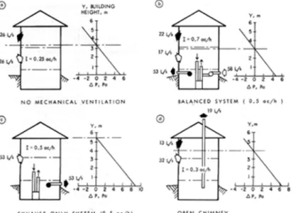
The ventilation air supply rate for a similar house equipped with an exhaust-only system is relatively insensitive to both wind and temperature difference and remains essentially constant. This is especially true for a system with a high exhaust rate. Figure 1a, Figure 1b, Figure 1c, & Figure 1d show the contributions of air infiltration, the mechanical ventilation system, and the chimney to the ventilation air supply of a two-storey house, measured on a calm day with an indoor-outdoor temperature difference of 28°C. All windows and exterior doors were tightly closed. Without mechanical ventilation (Figure 1a), the outdoor air pressure was greater than the indoor pressure at the lower levels; the reverse was true at the upper levels. Slightly above the floor level of the second storey the interior and exterior pressures were equal. This is called the neutral pressure level; below it, air infiltration occurs and above it, air exfiltration. The ventilation rate (I) supplied by air infiltration alone was 0.25 ac/h. (One air change per hour, ac/h, means that an amount of outdoor air equal to the volume of the house is supplied in one hour.)
Figure 1. Air flow and pressure patterns induced by temperature difference, chimney, and mechanical ventilation system
With a balanced system delivering an air-flow rate of 0.5 ac/h (Figure 1b), the ventilation air rate increased to about 0.7 ac/h. The system was, in fact, unbalanced; on entry, the cold outdoor air expanded so that the supply air rate exceeded the exhaust air rate by 5 L/s. As a result, the air pressure inside increased slightly, causing a decrease in the air infiltration rate and an increase in the air exfiltration rate.
With an exhaust-only system of 0.5 ac/h (Figure 1c), the ventilation air rate was equal to the exhaust air rate and the neutral pressure level was located at the ceiling level of the top storey. There was essentially no air exfiltration through the envelope.
Figure 1d shows the same house with a chimney added. As with exhaust fans, chimney action moved the neutral pressure level upwards to somewhere near the middle of the second storey, resulting in an increase in the ventilation rate from 0.25 to 0.3 ac/h. If a balanced system were installed, the ventilation air supply rate would increase but the house pressure and therefore the venting capacity of the chimney would not be affected significantly. With an exhaust-only system, the neutral pressure level would move upwards, reducing the house pressure and the venting capacity of the chimney. (If the neutral pressure level were to move above the ceiling level of the top storey, combustion gas spillage and/or chimney backdraft could occur.) For houses with chimneys, therefore, the ceiling level of the top storey is the maximum acceptable height of the neutral pressure level for satisfactory chimney performance, placing a limit on the size of the exhaust-only system.
Sizing of Mechanical Ventilation Systems
In practice, air infiltration is rarely considered in sizing ventilation systems because it is difficult to estimate. As a result, the amount of ventilation air received by a house under the
combination of mechanical ventilation and air infiltration often exceeds the design ventilation rate, causing unnecessary energy consumption. This is not serious under mild weather conditions because temperature differences are small, but in winter it can be extremely wasteful. For a house with a 0.5 ac/h balanced system and an air infiltration rate of 0.25 ac/h, the amount of ventilation air received can exceed the air flow rate of the mechanical ventilation system by as much as 40 percent (Figure 1b).
To satisfy the ventilation requirement a mechanical ventilation system should be capable of delivering the design ventilation rate. To conserve energy in winter it could be equipped with a flow controller such as a two-speed fan and operate under reduced flow to take advantage of the increased air infiltration. A manual switch or an indoor humidistat could be used to increase flow for quick removal of odours, moisture, and fumes. In addition, an outdoor temperature controller could be installed to increase air flow in mild weather.
Winter operation
The air-flow rate for winter operation can be determined on the basis of the design ventilation rate and mean air infiltration rate. Recommended design ventilation rates for houses are listed in various standards. For typical houses an outdoor air supply rate of 0.5 ac/h would be a reasonable value, although there are indications that it is too high. A ventilation rate of 0.35 ac/h has been proposed in the revised ASHRAE standard.
The mean air infiltration rate for the winter months is proportional to the air tightness of the house and can best be determined by a fan pressurization test. This involves the use of a fan to create suction in the house being tested, and measurement of the air-now rate through the fan and the corresponding pressure difference across the house envelope. The measured air-flow rate is the air-tightness value of the house at the induced pressure difference. The range of airtightness values for 40 low-energy houses is given in Table 1.
Table 1. Range of air-tightness values for low-energy houses House Rating ac/h, 10 Pa
Bungalow Tight 0.13 Average 0.43 Loose 0.73 Two-storey Tight 0.17 Average 1.05 Loose 1.93 Other Tight 0.16 Average 0.49 Loose 0.81
Based on the mean air infiltration rate for winter months, estimated from the air-tightness value, the air-flow rates for winter operation of a balanced system and an exhaust-only system are given in Figure 2 (a and b) for various design ventilation rates. For example, in a two-storey low-energy house with an average tightness value of 1 ac/h at 10 Pa, the winter air-flow rate of a mechanical ventilation system designed to meet the 0.5 ac/h ventilation
requirement would be 0.38 and 0.4 ac/h for balanced and exhaust-only systems, respectively.
Figure 2. Air-flow rate of a mechanical ventilation system required for winter operation Figure 2(b) also shows the maximum allowable airflow rate for houses with chimneys. If a greater rate is needed, intake openings must be installed in the exterior walls to avoid possible chimney backdraft. A better alternative could be a balanced system.
Air Distribution
In spite of an adequate supply of ventilation air for the house as a whole, there may be inadequate supply for some rooms because of poor distribution. With forced-air heating systems the most effective and economical way of distributing ventilation air is to use the existing air ducts. This can be achieved by connecting the supply air duct of a balanced system to the return duct of the forced-air heating system, if permitted by the prevailing building codes and standards. Otherwise, the supply duct should be terminated near a main return-air grille of the forced-air heating system. For houses without such systems an air distribution network might be necessary to implement a balanced flow. An alternative would be an exhaust-only system, with intake openings installed in the exterior wall where needed to ensure proper distribution of outdoor air. An opening in the exterior wall might appear to contradict the purpose of tightening houses, but it is a practical and inexpensive method of ensuring adequate ventilation air.