Publisher’s version / Version de l'éditeur:
Journal of ASTM International, 7, 1, pp. 44-62, 2010-01-01
READ THESE TERMS AND CONDITIONS CAREFULLY BEFORE USING THIS WEBSITE. https://nrc-publications.canada.ca/eng/copyright
Vous avez des questions? Nous pouvons vous aider. Pour communiquer directement avec un auteur, consultez la
première page de la revue dans laquelle son article a été publié afin de trouver ses coordonnées. Si vous n’arrivez pas à les repérer, communiquez avec nous à PublicationsArchive-ArchivesPublications@nrc-cnrc.gc.ca.
Questions? Contact the NRC Publications Archive team at
PublicationsArchive-ArchivesPublications@nrc-cnrc.gc.ca. If you wish to email the authors directly, please see the first page of the publication for their contact information.
Archives des publications du CNRC
This publication could be one of several versions: author’s original, accepted manuscript or the publisher’s version. / La version de cette publication peut être l’une des suivantes : la version prépublication de l’auteur, la version acceptée du manuscrit ou la version de l’éditeur.
For the publisher’s version, please access the DOI link below./ Pour consulter la version de l’éditeur, utilisez le lien DOI ci-dessous.
https://doi.org/10.1520/JAI102334
Access and use of this website and the material on it are subject to the Terms and Conditions set forth at
Comparisons of temperature and heat flux in furnaces controlled by
different type of temperature sensors
Sultan, M. A.
https://publications-cnrc.canada.ca/fra/droits
L’accès à ce site Web et l’utilisation de son contenu sont assujettis aux conditions présentées dans le site LISEZ CES CONDITIONS ATTENTIVEMENT AVANT D’UTILISER CE SITE WEB.
NRC Publications Record / Notice d'Archives des publications de CNRC: https://nrc-publications.canada.ca/eng/view/object/?id=2865c5c2-6048-488d-ad1f-4edcedb8d9e3 https://publications-cnrc.canada.ca/fra/voir/objet/?id=2865c5c2-6048-488d-ad1f-4edcedb8d9e3
Com pa risons of t e m pe ra t ure a nd he a t flux in furna c e s c ont rolle d by
diffe re nt t ype of t e m pe ra t ure se nsors
N R C C - 5 1 1 7 3
S u l t a n , M . A .
J u l y 2 0 1 0
A version of this document is published in / Une version de ce document se trouve dans:
Journal of ASTM International, 7, (1), pp. 44-62, January 01, 2010, DOI:
10.1520/JAI102334
The material in this document is covered by the provisions of the Copyright Act, by Canadian laws, policies, regulations and international agreements. Such provisions serve to identify the information source and, in specific instances, to prohibit reproduction of materials without written permission. For more information visit http://laws.justice.gc.ca/en/showtdm/cs/C-42
Les renseignements dans ce document sont protégés par la Loi sur le droit d'auteur, par les lois, les politiques et les règlements du Canada et des accords internationaux. Ces dispositions permettent d'identifier la source de l'information et, dans certains cas, d'interdire la copie de documents sans permission écrite. Pour obtenir de plus amples renseignements : http://lois.justice.gc.ca/fr/showtdm/cs/C-42
Comparisons of Temperature and Heat Flux in Furnaces
Controlled by Different Type of Temperature Sensors
Mohamed A. Sultan Fire Research Program Institute for Research in Construction National Research Council of Canada
Ottawa, Ontario, Canada mohamed.sultan@nrc.gc.ca
ABSTRACT
This paper presents and discusses furnace temperature and heat flux measurements in a fire resistance floor furnace controlled by ASTM shielded thermocouple probes, ISO 834 plate thermometers, directional flame thermometers and bare bead thermocouples. Comparisons of furnace temperature measurements, temperature sensor time constants; incident heat flux and measured vs predicted incident heat flux are presented.
Keywords: fire resistance, furnace, shielded thermocouple probes, plate thermometers, directional flame thermometers, bare bead thermocouples, time constant, incident heat flux
INTRODUCTION
With the advent of performance-based codes and performance-based fire safety design options, there is a growing needs by the fire protection engineering community for data from the standard fire tests such as ASTM 119 [3] and ISO 834-1 [4] that are not currently measured or required by the standard. The lack of engineering data from standard fire resistance test methods poses challenges and sometimes leads to utilizing data from ad hoc methods that are outside the scope of standard test methodology.
In response to the needs of the fire protection engineers, a recently-completed study [1] on fire resistance testing for performance-based fire design of buildings has made several recommendations pertaining furnace instrumentation and operation that are potentially relevant to the existing ASTM E119 fire resistance standard [2]. These recommendations are being considered by the ASTM E05 Committees on fire standards. In the instrumentations area, the use of the plate thermometer to measure the furnace temperature has been recommended. If ASTM were to adopt this recommendation, the impact of this change on the previously tested assemblies over the past century could be a challenge. In the furnace operations area, a calibration test to quantify the thermal exposure has also been recommended. Defining the thermal exposure in fire resistance test furnaces is also a challenge for fire protection engineers and standards-writing organizations. Defining thermal performance of building elements is an essential component of structural fire safety design. In a recent study by the author [4] on the comparison of furnace gas temperature and incident heat flux in furnaces
controlled by the ASTM shielded thermocouple probes vs plate thermometersshowed that in the initial fire exposure (up to 8 min) the difference in measured furnace temperature is significant, however, after 8 min, the difference is insignificant. The ASTM shielded thermocouple probes have a larger time constant (5 to 7.2 min) compared to the ISO plate thermometers (40 s). In the first 8 min, the furnace temperature rise is quite steep and the time constant plays a significant role, however, after 8 min the furnace temperature rise level off and therefore, the time constant after 8 min becomes insignificant.
ASTM E119 “Standard Test Methods for Fire Tests of Building Construction and Materials” specifies the time constant for thermocouples used in measuring the furnace temperature in the range from 5 to 7.2 min. The standard also provides a note that describes a thermocouple design that achieves the required time constant “a typical thermocouple assembly that meets the time constant requirements it can be fabricated by fusion-welding the twisted ends of No. 18 gauge Chromel-Alumel wires, mounting the leads in a porcelain insulator and inserting the assembly so the thermocouple bead is ½ in. from the sealed end of a standard weight nominal ½ in. iron or steel or Inconel pipe”. It should be noted that the time constant of the ASTM E119 shielded thermocouple probe, plate thermometer, directional flame thermometer and bare thermocouple changes continuously during the fire test because the total heat transfer coefficient
changes. Babrauskas and Williamson [5] provided a detailed analysis of the time
response of thermocouples and showed that the errors associated with temperature measurements in fire resistance test furnaces are significant in the first 20 minutes of a test. The time constant when convection is dominant is given by the following equation [5]:
where:
τ = time constant (s),
ρ = density of the bead material (kg/m³),
Cp = specific heat capacity of the bead material (J/kg.K),
V = volume of the bead (m³),
A = surface area of the bead (m²) and h = total heat transfer coefficient (W/m².K)
In fire test furnaces, where radiation is the dominant heat transfer mechanism, the time response constant can be estimated from the following equation [5]
τ= (Tf –Tt) (Δt)/ ΔTt (2)
where:
Tf = furnace temperature measured by a bare bead thermocouple
Tt =furnace temperature measured by a thermocouple or a thermometer
ΔTt= furnace temperature measured by a thermocouple or a thermometer at Δt
Two potential sensors for determining the heat flux in fire resistance test furnaces namely: the plate thermometers and the directional flame thermometers are available for consideration by the ASTM E05 committee. The ISO 834 fire resistance standard requires the plate thermometer for controlling the furnace temperature while the directional flame thermometer is under consideration by ASTM E05 Committee for measuring the heat flux in ASTM E1529 standard [6]. In the June 2008, ASTM E05.11 subcommittee meeting, a Task Group was initiated with a mandate of developing a new standard on measuring heat exposure in fire resistance test standards. The results reported in this paper will be part of the discussion that may lead to the selection of a
method for measuring the heat flux that to be adopted by ASTM in its fire resistance standards.
The ISO standard [3] specifies the design detail of these thermometers in Section 5.5.1.1.; unlike the ASTM E119 Standard where only the time constant for the thermocouples was specified. Laboratories that conduct tests according to the ISO 834 standard have no choice but to use the plate thermometer design specified in the standard. The time constant for the plate thermometers has been reported as 40 s [6]. The plate thermometer was developed by the SP (Technical Research Institute of Sweden) and adopted for use in the ISO 834 and EN 1363-1 fire resistance standards in1999. Before the adoption of the plate thermometers in the ISO fire resistance standard, a series of calibration tests was conducted in 14 European fire resistance furnaces [8]. It was found that, when the furnaces were controlled by the bare bead thermocouples, the results for a specified test specimen were considerably different due to variations in furnace characteristics and design of the thermocouples used for monitoring the furnace temperature. Subsequently, a second series of calibration tests was carried out in three laboratories using the plate thermometer. In second series, the results were in good agreement among the three laboratories [8]. Wickström [8] developed a methodology for estimating the heat transfer to a fire-exposed structure based on the concept of an adiabatic surface temperature, which is what plate thermometers are approximately measuring.
The directional flame thermometer (DFT) was originally developed by Winfrith at AEA Technologies in the UK to estimate the effective radiation temperature in pool fire tests of radioactive material shipping containers. Sandia National Laboratories (in Albuquerque, NM) adapted the original design by adding a second plate to the DFT
where the goal was to provide both transient and quasi-steady heat transfer measurements in various fire environments.
To investigate the two recommendations that are related to the furnace instrumentation and thermal exposure in Reference [1], the National Research Council of Canada has conducted several studies to characterize the thermal environment in fire resistance test furnaces using various temperature and heat flux sensors. This paper presents the results of four one-hour fire resistance tests carried out in a full-scale floor furnace using five water-cooled Gardon heat flux gauges, five ASTM E119 shielded thermocouple probes, five ISO plate thermometers, five directional flame thermometers and five bare bead thermocouples. In each of the four tests, one of the four types of temperature sensors was used to control the furnace. Comparisons of the measured temperature and measured vs predicted incident heat fluxes obtained in these four tests is discussed below.
EXPERIMENTAL STUDY
The heat flux gauges and temperature sensors that were used in this study are described below.
Heat Flux Sensor
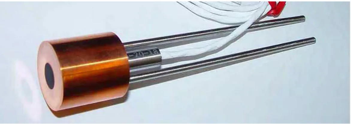
Five water-cooled Gardon heat flux gauges were used to measure the total incident heat flux to a specimen in the furnace. The gauges are cooper cylinder, 25 mm in diameter and 25 mm long (Figure 1). The Gardon gauge is named after its inventor whose use is described in ASTM standard E511-07. The gauge consists of a circular constantan foil connected to a water cooled copper hollow cylinder that acts as a heat sink. The heat flux absorbed at the gauge surface and flows radially from the centre of
the foil to the cooled edge. Under steady state conditions, this results in a nearly parabolic temperature distribution. This sensor works like a differential thermocouple whose output is proportional to the absorbed incident heat flux.
Temperature Measurement Sensors
Four different sensors were used to measure the furnace temperature: ASTM shielded thermocouple probes, ISO plate thermometers, directional flame thermometers and bare bead thermocouples.
ASTM E119 Standard Shielded Thermocouples
The shielded thermocouple probes was fabricated by fusing the twisted ends of No. 18 gage Chromel-Alumel wires mounted inside a porcelain insulator. The
thermocouple with the porcelain insulator was inserted inside a 12.7 mm diameter Inconel pipe so that the thermocouple bead was 12.7 mm away from a sealed end cap. The shielded thermocouple probe is shown in Figure 2. Five shielded thermocouples were used: one at the centre of the furnace and one at the centre of each quarter section. These thermocouples probes were located 300 mm below the fire-exposed surface of the test specimen in the floor furnace in accordance to ASTM E119 standard. ISO 834 Standard Plate Thermometers
The plate thermometers used in this study were made by Thermo-Electra based on the description in Reference [8]. The plate thermometer consists of a 100 mm by 100 mm Inconel 600 plate, 0.7 mm thick, with a surface emissivity greater than 0.7. A Type K, 1 mm diameter, sheathed thermocouple is held against the centre of the back side of the plate. This side faces the test specimen and is insulated with10 mm thick ceramic fibreboard. The other front side of the plate faces the furnace. A schematic of the plate thermometer is shown in Figure 3. Five plate thermometers were used to record the
furnace temperature base on the ISO 834 fire resistance standard time – temperature curve. The plate thermometers were placed in the floor furnace close to those shielded thermocouple probes but at a distance of 100 mm below the test specimen as per ASO 834 standard. The time constant of the plate thermometer, as mentioned before, is estimated approximately 40 s [7]. It should be noted that the estimated time constant is of the plate thermometer changes continuously with furnace temperature as with the case for ASTM E119 shielded thermocouple probes.
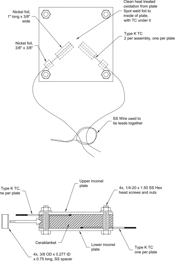
Directional Flame Thermometers
The directional flame thermometer consists of two 120 mm by 120 mm Inconel plates, 3 mm thick. Ceramic fibre insulation 19 mm thick is sandwiched between the two plates. Two sheathed Type K thermocouples with ungrounded junction are attached to the unexposed faces of the Inconel plate with a thin Nichrome foil spot-welded over the tip of the thermocouples. The exposed surfaces of the Inconel plates are coated with Pyromark 2500 black [9] or were heavily oxidized [10] to provide consistent radiation properties. The time constant for the directional flame thermometers is estimated approximately 89 s at the start of the test [11]. A schematic of the directional flame thermometer is shown in Figure 4.
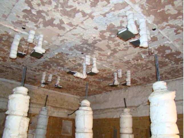
Full-scale Floor Furnace
The full-scale fire resistance floor furnace used in this study is approximately 3.9 m wide by 4.8 m long by 3 m deep. The furnace walls were made of insulated firebrick. Thermal properties of the furnace lining materials are given in Table 1.
Test Specimen
The test specimen was a castable refractory slab, marketed as KS-4, composed of 20 rectangular sections, 800 mm wide by 1200 mm long by 1500 mm thick, suspended on a steel beam. The thermal properties of the test specimen are given in Table 1. The sections were tightly butted with a ceramic sheet along their perimeters to form a 3.9 m by 4.8 m unit. To measure the incident heat flux received by the test specimen, five heat flux gauges were installed flush with the specimen surface: one at the centre of the furnace and one at the centre of each quarter section.
Furnace Temperature Measuring Sensors and Experimental Procedure
Four tests were conducted using a floor furnace: the first test with a furnace controlled by the average of five shielded thermocouple probes and the second test with a furnace controlled with the average of five plate thermometers, the third test with a furnace controlled by the average of five directional flame thermometers and the fourth test with a furnace controlled by the average of five bare bead thermocouples. In each test, the furnace was controlled electronically to closely follow the time-temperature curve specified in ASTM E119 standard. Measurements from the heat flux gauges and all temperature sensors were recorded in the four tests every five seconds.
RESULTS AND DICUSSION
The main mechanisms of heat transfer in fire resistance test furnaces are by radiation and to a certain extent by convection. The radiation heat transfer depends on the furnace hot gases temperature and emissivity as well as on the thermal conductivity and emissivity of furnace lining material. The use lining material with very low thermal
conductivity results in the furnace lining surface temperature being close to the hot
gases temperature. This helps the harmonization among different furnaces [12]. The
convective heat transfer depends in part on the furnace size and location of furnace burners and hot gases exit ports. In a larger furnace, convective heat transfer is primarily by natural convection where the burners are away from test specimen, however, in a small shallow furnace, the convective heat transfer could be dominated by forced convection due to proximity with the burners. `It is important to use a temperature-measuring device that senses both convective and radiation.
Furnace temperature measurements controlled by either the shielded thermocouple probes or by plate thermometers or by directional flame thermometers are discussed below.
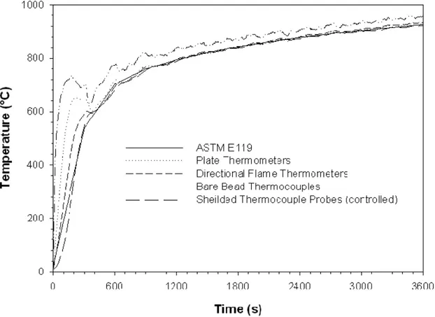
Floor Furnace Test with Temperature Control by Shielded Thermocouple Probes
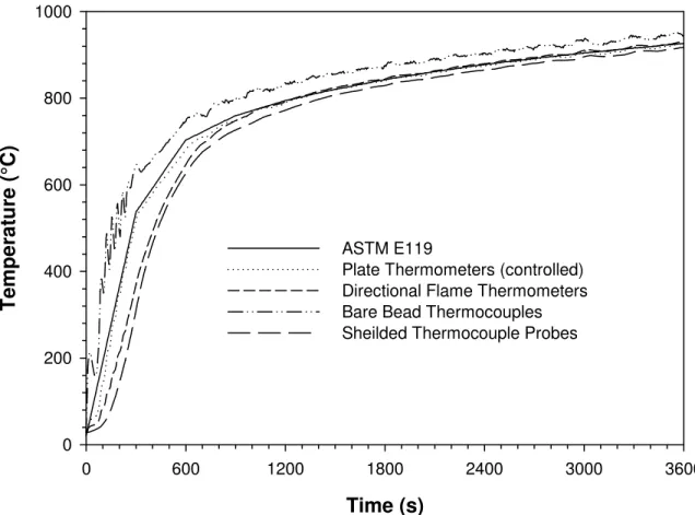
In the first test, the floor furnace temperature was controlled by the average of five-shielded thermocouple probes to follow the ASTM E119 time – temperature curve. A comparison of the average furnace temperatures measured with the four different types of sensors is presented in Figure 6. The results are consistence with the response time characteristics of the sensors. The furnace temperature rises rapidly at the start of the test. During this initial period, the bare bead thermocouple reading increase at the fastest rate. The shielded thermocouple probe reading increase at the slowest rate and the measured time-temperature curves for the two remaining sensors are in between. This could be explained as results of differences in the time constant of the temperature sensors. After approximately ten minutes, the furnace temperature start to level off and a few minutes later, the temperature readings from the shielded thermocouple probes,
plate thermometers and differential flame thermometers converge. However, the bare bead thermocouple readings continue to be higher for the remainder of the test. This is due to the fact that the ratio of convective vs. radiative heat transfer higher for the bare bead thermocouples compared to the other three sensors.
For an application requiring a 15 min fire resistance test, thermal exposure is more sever in a test controlled by shielded thermocouple probes than those controlled with the plate or directional flame thermometers.
Floor Furnace Test with Temperature Control by Plate Thermometers
In the second test, the floor furnace temperature was controlled by the average of five plate thermometers to follow the ASTM E119 time – temperature curve. A comparison of the average furnace temperatures measured with four different types of sensors is presented in Figure 7. The results are consistent with the response time characteristics of the four sensors and their sensitivity to convective vs. radiative heat transfer as discussed in the previous section.
In the furnace temperature measurements shown in Figure 7 for initial 10 minutes, the temperatures measured by the shielded thermocouple probes and directional flame thermometers are lower by up to 40% and 30%, respectively, and the bare bead thermocouples measured 25% higher temperature than those measured by the plate thermometers. This could be due to a larger time constant for the shielded thermocouple probes and directional flame thermometers than for plate thermometers. After 10 minutes, the ASTM E119 time-temperature increases at a slower rate and the measured temperatures by the all sensors except the bare bead thermocouple start to
level off. The bare bead thermocouple readings continue to be higher for the remainder of the test and this was explained the previous section.
Floor Furnace with Temperature Control by Directional Flame Thermometers
In the third test, the floor furnace temperature was controlled by the average of five directional flame thermometers to follow the ASTM E119 time – temperature curve. A comparison of the furnace average temperatures measured with four types of sensors is presented in Figure 8. The results are consistent with response time characteristics of the four sensors and their sensitivity to convective vs. radiative heat transfer as discussed in previous sections.
In the furnace temperature measurements shown in Figure 8 for a furnace controlled by the directional flame thermometers, the shielded thermocouple probes temperature measurements are lower by up to 25% and plate thermometers and bare bead thermocouples are higher by up to 30% and 50%, respectively, during the first 10 min of the fire exposure than those measured by the directional flame thermometers. This could be due to a larger time constant for the shielded thermocouple probes and lower time constant for plate thermometers and bare thermocouples than for directional flame thermometers. After 10 min of fire exposure, the directional flame thermometer is more or less same as the plate thermometer measurement; however, the shielded thermocouples measurements are slightly lower than the directional flame thermometers. This could be explained that after 10 min, the furnace temperature increases at a slower rate, so that the effect of the difference in time response constant for the shielded thermocouples and plate thermometers compared to the directional flame thermometers is insignificant.
Floor Furnace with Temperature Control by Bare Bead Thermocouples
In the fourth test, the floor furnace temperature was controlled by the average of five bare bead thermocouples to follow the ASTM E119 time – temperature curve. A comparison of furnace average temperature measured with four types of sensors is presented in Figure 9. Since the bare bead thermocouples have a fast response time,
using them to control the furnace is a challenge. During the first 10 min of the test, the
shielded thermocouple probes, plate thermometers and directional flame thermometers are all measuring lower temperature than the bare bead thermocouple by 75%, 65% and 50%, respectively. This is because the time constant for theses the three sensors are larger than those of the bare bead thermocouples. After 10 min of fire exposure, the three sensors measured more or less the same temperature; however, these were lower by 8% than the bare bead thermocouples.
Temperature Lag with Respect to Bare Bead Thermocouples Measurements
To quantify the temperature lag, temperature measurements of the shielded thermocouples probes, plate thermometers and directional flame thermometers, furnace controlled by the shielded thermocouples probes, were subtracted from the bare bead
thermocouple measurements and are plotted in Figure 10. The results show that in the
first 10 min, the temperature lag is significant, but after 10 min, the temperature lag becomes negligible. However, a relatively small temperature bias remains after 10 min due to differences of the sensors’ sensitivity to convective vs. radiative heat transfer.
Temperature Measurement Sensors Time Constant
The time constant of the shielded thermocouple probes, plate thermometers and directional flame thermometers calculated according to Equation 2 are plotted in Figure 11. The figure shows that the time constant is slightly higher for the directional flame thermometers than the plate thermometers. However, both have a shorter time constant than the shielded thermocouples probes.
Floor Furnace Incident Heat Flux Measurements
Incident heat fluxes measured with the five Gardon-type wide-angle heat flux gages in the floor furnace are shown in Figure 12.
The results indicate that when a floor furnace is controlled by shielded thermocouples probes, the gauges received an incident heat flux during the first 10 min that is higher by up to 200% or up to 100% than when the same furnace is controlled by plate thermometers or by directional flame thermometers. After 10 min the gauges received approximately the same incident heat flux when the furnace is controlled either by the plate thermometers or by directional flame thermometers. However, in the case when the furnace is controlled by the shielded thermocouple probes, the gauges received approximately 7% more heat flux than when the furnace is controlled by either plate thermometers or by directional flame thermometers. However, the measured heat flux with furnace controlled by bare bead thermocouples is lower than those controlled by the other sensors. These results are consistent with the measured furnace temperatures in the first three tests.
The incident heat flux in furnace can be estimated from the following equation, assuming the convective heat transfer is small. As noted below, this assumption is not accurate during the first 5 to 10 min of the test.
Q =ε σ T4
(3)
where T is the furnace temperature (controlled) measured by the shielded thermocouple probes or plate thermometers or directional flame thermometers.
The estimated incident heat flux based on the ASTM E119 time-temperature curve for a furnace controlled by shielded thermocouple probes, plate thermometers or directional flame thermometers is presented in Figures 13, 14 and 15, respectively. The predicted heat flux in the first 10 min of fire exposure is much lower than the measured heat flux by Gardon gages. This could be due to the neglecting of the convective heat transfer, which is more predominant in the early stage in fire resistance test furnaces. After 10 min of exposure, the predicted heat flux is up to 10% lower than the measured value for a furnace controlled by plate thermometers or directional flame thermometers. The reason for the lower prediction is again due to the neglect of the convective heat transfer, which is less significant at high temperatures.
SUMMARY OF RESULTS
This paper discusses four methods for controlling the furnace temperature in a floor fire resistance furnace. It also discusses the heat flux received by a specimen in a floor furnace controlled by shielded thermocouple probes or plate thermometers, directional flame thermometers or bare bead thermocouples. In addition, comparisons of the predicted and measured incident heat flux for the four methods studied are
presented. Based on the results mentioned above, the following key trends can be highlighted:
1. For the initial fire exposure up to 10 min, the difference between furnace temperatures measured by shielded thermocouple probes, plate thermometers, directional flame thermometers and bare bead thermocouples is significant regardless of the type of the sensors used to control the furnace. However, after 10 min, the difference becomes insignificant except for the bare bead thermocouple measurements, which are slightly lower than the temperatures measured with the other three types of sensors.
2. During the initial 10 min fire exposure in a floor furnace controlled by the shielded thermocouple probes or by directional flame thermometers, the specimen receives peak heat fluxes that are up to 100% and up to 50% higher, respectively, than in the test controlled by the plate thermometers. However, after 10 min, these peak heat fluxes are up to 10% and 5% higher, respectively.
3. Predicted heat fluxes in the furnace tests controlled by plate thermometers or direction flame thermometers are about 10% less than the heat fluxes measured with Gardon gauge sensors.
ACKNOWLEDGEMENTS
The author wishes to thank Jocelyn Henrie and Yves Seguin of the Fire research Program, National Research Council Canada for their help in conducting the experimental work.
REFERENCES
1. Beyler, C., Beitel, J, Iwankiw, N. and Lattimer, B., “Fire Resistance Testing for Performance-based Fire Design of Buildings”, FPFR Report, 1 Batterymarch Park, Quincy, MA 02169 – 7471, 2007.
2. ASTM E119-88, “Standard Methods of Fire Tests of Building Constructions and Materials”, ASTM, Philadelphia, PA, 1995.
3. ISO 834-1, “Fire Resistance Tests Elements of Building Construction – Part 1” 4. Sultan, M. A., “Fire Resistance Furnace Temperature Measurements: Plate
Thermometers vs. Shielded Thermocouples”, Fire Technology, 2008.
5. Babrauskas, V and Williamson, R. B., “Temperature Measurement in Fire Test Furnaces”, Fire Technology, Vol.14, No. 3, 1978.
6. ASTM standard 1529-00, “Standard Test Methods for Determining Effects of Large Hydrocarbon Pool Fires on Structural Members and Assemblies1 “, ASTM, Philadelphia, PA, 2000.
7. Wickström, U.,”The Plate Thermometer – Practical Aspects”, SP- Report 1997:28, Swedish National Testing and Research Institute, 1997.
8. Wickström, U., “Adiabatic Surface Temperature and the Plate Thermometer for Calculating Heat Transfer and Controlling Fire Resistance Furnaces” Fire Safety Science Proceedings of Ninth International Symposium, 2008 .
9. Longenbaugh, R.S. et al, Thermal Response of a Small Scale Cask-Like Test Article to Three Different High Temperature Environments”, Sandia National Laboratories Report to Federal Rail Administration, DOT/FRA/ORD- 90/01, Feb. 1990.
10. Keltner, N.R., “Directional Flame Thermometers: A Tool for Measuring Thermal Exposure in Furnaces and improving Control” Interflam 2007, Proceedings of the Eleventh International Conference, Interscience Communications, 2007.
11. Keltner, Ned, private communication 2008.
12. The European Standard EN 1363-1:1999, “Fire Resistance Tests – Part 1: General Requirements”, European Committee for Standardization, rue de Stassart 36, B-1050 Brussels, 1999.
13. Sultan, M. A. and Denham, M. “Harmonization of the Fire Severity in Standard Fire Resistance Test Furnaces”, Fire Safety Sciences – proceedings of the Fifth International Symposium, 1997.
Table 1 Thermal Property of Furnace Lining Furnace Lining Fire-brick Test Specimen Material (Castable Refractory Slab) Thermal Conductivity (W m -1K –1) 1.15 0.9 Specific Heat (J kg -1 K -1) 900 1000 Density (kg m-3 ) 2600 2085
S S W i r e u s e d t o t i e l e a d s t o g e t h e r C l e a n h e a t t r e a t e d o x i d a t i o n f r o m p l a t e S p o t w e l d f o i l t o i n s i d e o f p l a t e , w i t h T C u n d e r i t T y p e K T C 2 p e r a s s e m b l y , o n e p e r p l a t e N i c k e l f o i l , 1 " l o n g x 3 / 8 " w i d e N i c k e l f o i l , 3 / 8 " x 3 / 8 " 4 x , 1 / 4 - 2 0 x 1 . 5 0 S S H e x h e a d s c r e w s a n d n u t s U p p e r i n c o n e l p l a t e L o w e r i n c o n e l p l a t e T y p e K T Co n e p e r p l a t e T y p e K T C , o n e p e r p l a t e 4 x , 3 / 8 O D x 0 . 2 7 7 I D x 0 . 7 5 l o n g , S S s p a c e r C e r a b l a n k e t
Figure 6. Temperature Measurements in Furnace Controlled by Shielded Thermocouple Probes.
Figure 7. Temperature Measurement in Furnace Controlled by Plate Thermometers. 0 200 400 600 800 1000
Time (s)
Temperat
ure (°C)
ASTM E119Plate Thermometers (controlled) Directional Flame Thermometers Bare Bead Thermocouples Sheilded Thermocouple Probes
igure 8. Temperature Measurements in Furnace Controlled by Directional Flame F 0 200 400 600 800 1000 Thermometers.
Time (s)
Temperature (°C)
ASTM E119 Plate ThermometersDirectional Flame Thermometers (controlled) Bare Bead Thermocouples
Sheilded Thermcouple Probes
Figure 9. Temperature Measurements in Furnace Controlled by Bare Bead Thermocouples. 0 200 400 600 800 1000
Time (s)
Temperat
ure (°C)
ASTM E119 Plate ThermometersDirectional Flame Thermometers Bare Bead Thermocouples (controlled) Sheilded Thermocouple Probes
0 100 200 300 400 500 600 700
Figure 10. Temperature Differences between Shielded Thermocouple Probes, Plate Thermometers and Directional Flame Thermometers and Bare Bead Thermocouples.
Time (s)
Temperature Difference (°C)
Bare Bead Thermocouples - Sheilded Thermocouple Probes Bare Bead Thermocouples - Plate Thermometers
Bare Bead Thermocouples - Directional Flame Thermometers
Time (s)
0 600 1200 1800 2400 3000 3600T
im
e C
onstant (
s
)
0 200 400 600 800 1000 Plate ThermometersDirectional Flame Thermometers Sheilded Thermocouple Probes
Figure 11. Time Constant of Shielded Thermocouple Probes, Plate Thermometers and Directional Flame Thermometers.
0 20 40 60 80 100 120 140
Figure12. Incident Heat Flux Measurements in Furnace Controlled by Shielded Thermocouple Probes, Plate Thermometers and Directional Flame
Thermometers.
Time (s)
Hea
t F
lux
(kW
/m
2)
Sheilded Thermocouple Probes (controlled) Plate Thermometers (controlled)
Directional Flame Thermometers (controlled) Bare Bead Thermocouples (controlled)
0 20 40 60 80 100 120 140 160
Figure 13. Measured and Predicted Incident Heat Flux in Furnace Controlled by Shielded Thermocouple Probes.
Time (s)
Hea
t Fl
ux
(kW
/m
2)
Measured by Sheilded Thermocouple Probes (controlled) Predicted Based on Sheilded Thermocouple Probes
Figure14. Measured and Predicted Incident Heat Flux in Furnace Controlled by Plate Thermometers. 0 20 40 60 80 100 120 140
Time (s)
Hea
t F
lux
(kW
/m
2)
Measured by Plate Thermometers (controlled) Predicted Based on Plate Thermometers
0 20 40 60 80 100 120 140
Figure 15. Measured and Predicted Incident Heat Flux in Furnace Controlled by Directional Flame Thermometers.
Time (s)
Hea
t Fl
ux
(kW
/m
2)
Measured by Directional Flame Thermometers (controlled) Predicted based on Directional Flame Thermometers