https://doi.org/10.4224/20378714
Vous avez des questions? Nous pouvons vous aider. Pour communiquer directement avec un auteur, consultez la première page de la revue dans laquelle son article a été publié afin de trouver ses coordonnées. Si vous n’arrivez pas à les repérer, communiquez avec nous à [email protected].
Questions? Contact the NRC Publications Archive team at
[email protected]. If you wish to email the authors directly, please see the first page of the publication for their contact information.
https://publications-cnrc.canada.ca/fra/droits
L’accès à ce site Web et l’utilisation de son contenu sont assujettis aux conditions présentées dans le site LISEZ CES CONDITIONS ATTENTIVEMENT AVANT D’UTILISER CE SITE WEB.
READ THESE TERMS AND CONDITIONS CAREFULLY BEFORE USING THIS WEBSITE.
https://nrc-publications.canada.ca/eng/copyright
NRC Publications Archive Record / Notice des Archives des publications du CNRC :
https://nrc-publications.canada.ca/eng/view/object/?id=b3c55fee-db1a-4ad3-adad-884209387011
https://publications-cnrc.canada.ca/fra/voir/objet/?id=b3c55fee-db1a-4ad3-adad-884209387011
NRC Publications Archive
Archives des publications du CNRC
For the publisher’s version, please access the DOI link below./ Pour consulter la version de l’éditeur, utilisez le lien DOI ci-dessous.
Access and use of this website and the material on it are subject to the Terms and Conditions set forth at
Performance compliance for buildings: specifications for calculation
procedures for demonstrating compliance to the model National
Energy Code for Buildings using whole building performance
National Research Council of Canada. Canadian Commission on Building
and Fire Codes
National Research Council Conseil national de recherches Canada Canada
Canadian Commission on
Building and Fire Codes
Performance Compliance for
Buildings
Specifications for Calculation Procedures
for Demonstrating Compliance
to the Model National Energy Code for Buildings
Using Whole Building Performance
PREFACE
The Model National Energy Code for Buildings 1997 (MNECB) features two types of requirements: mandatory, mostly qualitative, requirements which must be met by all proposed designs; and prescriptive, quantitative, requirements for which the MNECB provides three optional paths to show compliance:
1. Prescriptive Compliance 2. Trade-off Compliance 3. Performance Compliance
Prescriptive Compliance
A proposed design will comply with the prescriptive requirements of the MNECB if the thermal characteristics relating to space heating and cooling; e.g. overall thermal transmittance of walls, HRV (heat recovery ventilator) efficiency, are equal to or lower than the prescriptive requirements provided in Sections 3.3., 4.3., 5.3. and 6.3. of the MNECB. This is the simplest compliance path and requires no performance calculation.
Trade-off Compliance
Section 3.4. of the MNECB allows deviation from some of the prescribed envelope requirements, provided that other envelope components compensate so that the net space heating and cooling requirement is less than or equal to that which would result from the prescriptions. Two methods of envelope trade-off compliance are provided. Subsection 3.4.2. of the MNECB states that compliance can be achieved by showing that the sum of the areas of all above-ground assemblies multiplied by their respective overall thermal transmittances is no greater than it would be if all assemblies
complied with prescriptions. Subsection 3.4.3. of the MNECB allows compliance to be demonstrated using computer software that evaluates envelope trade-offs using a specified calculation procedure.
Performance Compliance
Performance compliance is an option (described in Part 8 of the MNECB) that permits a proposed design to deviate from prescriptive requirements provided that the proposed design can be shown, using computer software (compliance software), to have an annual adjusted energy consumption for space heating no greater than that of a reference case that satisfies the prescriptive requirements. The MNECB specifies that software used for this purpose comply with this specification.
This document specifies the various functions that the compliance software must be capable of performing in order to assist a user in demonstrating that a proposed design complies with the MNECB. The intended audience for this specification is the software development agency that will develop or adapt software and related manuals for this purpose.
Statement of Intent
In general, the purpose of the performance compliance procedure is not to develop an accurate prediction of annual energy use for space heating. Rather, the purpose is to develop fair and consistent evaluations of the effects of deviations (in whatever direction) from MNECB prescriptive requirements. As such, many simplifying assumptions were made to rationalize the modeling exercise without compromising the intent.
Further, a number of occupant practices may result in energy conservation; for example, lowering or setting back thermostats. The performance analysis will not account for these measures. Since the performance path is used to allow deviations from MNECB prescriptive requirements, it was felt that occupant behavior should not be relied upon to achieve consistent and permanent reductions in
building energy consumption. As well, some energy saving measures depend on the occupant for proper functioning to save energy; for example, insulating shutters for windows, and attached sun spaces that don’t incorporate heating systems. It is generally acknowledged that such devices can save energy when used for that purpose, and the MNECB will not discourage their use; nevertheless, it was felt that the overall intent of the MNECB would be compromised if the removal of other, more permanent energy efficient measures (such as envelope insulation) were to be allowed in favour of occupant-sensitive measures.
In summary, a wide range of characteristics determine the energy efficiency of a building. The MNECB will require some of these to meet prescribed levels of energy efficiency, and will allow some others to be used instead of the prescriptive requirements through the trade-off and performance paths. Beyond these minimum requirements, it is expected that many conservation features not required by the MNECB and not included in the scope of the performance compliance path will continue to be demanded by the consuming public and contribute to the overall energy efficiency of buildings.
TABLE OF CONTENTS
Preface ………..………. i
Chapter 1 Introduction ………1-1
Chapter 2 Terminology ………. 2-1
Chapter 3 Compliance Software − General ……….. 3-1 Chapter 4 Compliance Shell: Processing Input for the Proposed Design ……… 4-1
Chapter 5 Compliance Shell: Generation of Reference Case ………….………. 5-1
Chapter 6 Compliance Software: Output Reports ……….………. 6-1
Chapter 7 Energy Analysis Module: Calculation Capabilities .……….. 7-1
Appendix A Equipment Performance Characteristics ……….……….. A-1
CHAPTER 1
INTRODUCTION
This document is a supplement to Part 8 of the Model National Energy Code for Buildings (MNECB) 1997, which will herein be referred to as the Code. Parts 1 to 7 of the Code contain mandatory and prescriptive requirements for building envelope, lighting and electrical systems, space conditioning and service water heating. Part 8 is provided as an alternative to the prescriptive requirements in order to permit more flexibility in design while still achieving the objectives of the
Code.
The basic principle of Part 8 is that a design may depart from the prescriptive requirements if it can be shown, using an approved computerized analysis procedure, that the energy performance of the
proposed design is as good or better than a building energy target that is based on the prescriptive requirements.
The building energy target is determined by modeling a reference case that has the same geometry and size as the proposed design, and in which envelope and lighting are based on the prescriptive requirements. Mechanical systems for the reference building are defined to be reasonable performance targets and are also based on the prescriptive requirements.
The building energy target is defined as the sum of the “adjusted” annual energy consumption for space conditioning, lighting, and service water heating. The adjustment is needed in order to bring energy from different sources, such as electricity and gas, to a common basis for comparison. This is necessary because the proposed design may, for example, use less cooling (electricity) but more heating (gas) than the reference case.
The energy source adjustment factors are contained in the Code and are based on a valuation (by provincial authorities) of each source. This is usually consistent with the relative costs of energy, sometimes with an additional allowance to account for environmental factors.
The process of defining a reference case, and from this calculating the building energy target, is transparent to the user of the Code. This is automatically done by the compliance software. The
Code user simply defines the proposed design, along with the necessary Code information. The software then:
• defines the reference case, models its energy performance and performs the energy source adjustment to determine the building energy target;
• models the proposed design and performs the energy source adjustment to determine annual adjusted energy consumption; and
• compares the annual adjusted energy consumption to the building energy target to determine whether the design complies (if annual adjusted energy consumption is no greater than the
building energy target, then it passes).
Chapters 3 through 7 of this document describe the requirements for the compliance software. Chapter 3 contains general requirements. Chapters 4 and 5 describe requirements for input data checking and the rules for defining the reference case. Chapter 6 contains reporting requirements and Chapter 7 describes the required characteristics of the energy calculation method used by the
compliance software.
Precedence of the MNECB
This document describes the calculation procedure for performance compliance as given in Part 8 of the MNECB and is subject to changes made necessary by revisions to the MNECB. It must be read in conjunction with the relevant requirements of the MNECB, which is a binding document that establishes the rules for performance compliance. Where discrepancies occur between the present document and the MNECB, the MNECB shall govern.
CHAPTER 2
TERMINOLOGY
2.1. Terms Italicized in the Text
Words or phrases that appear in italics in this document are defined terms intended to have a specific meaning. Terms that are defined in Section 2.2., Definitions, of this document shall have the
meaning given in those definitions. Terms in italics that are not defined in Section 2.2. of this document shall have their meaning defined in the MNECB.
Words and phrases used in this document that are not defined in Section 2.2. of this document and are not defined in Article 1.1.3.2. of the MNECB shall have the meanings that are commonly assigned to them in the context in which they are used in this document and in the MNECB, taking into account the specialized use of terms within the various trades and professions to which the terminology applies.
2.2. Definitions
The words and terms in italics in this document are defined as follows, or are defined under Article 1.1.3.2. of the MNECB:
Building type meansone of the categories in Table 4.3.2.A. of this document.
Code means theModelNational Energy Code for Buildings 1997.
Primary system meansa system that consists of the equipment to convert electricity or fuel to heating or cooling and distribute it to one or more secondary systems, where such equipment is not already defined as part of the secondary system (e.g. boilers and chillers).
Proposed design meansthe building, group of buildings or portions of the building for which construction approval is being sought. The proposed design includes the building envelope, lighting and electrical systems, and mechanical systems to provide space conditioning and service water
heating.
Reference case means a generic building design of the same size and shape as the proposed design that complies with the prescriptive requirements of the MNECB and has prescribed assumptions, as given in Chapter 5 of this document, used to generate the energy target.
Secondary system meansa system that provides air (for ventilation as well as distribution of heating and cooling) to the thermal block (i.e. fan system). Secondary systems may include equipment dedicated to the system that converts electricity or fuel to heating or cooling. Secondary systems may be “single zone” (serving only a single thermal block), or multiple zone (serving one or more
Space function meansoneof the categories given in Table 4.3.2.B. of this document.
Space use classification isused to identify the characteristics of the space in a thermal block. Selected according to either building type from Table 4.3.2.A. or space function from Table 4.3.2.B. of this document, space use classification determines the default values of occupant density, lighting power, receptacle power, ventilation rate and operating schedules.
Terminal characteristics means those features and parameters that pertain only to the
thermal block served, and are not included in the definition of the secondary system.
Thermal block: a space, or group of spaces, that is considered as one homogeneous space for modeling purposes. A thermal block should be:
(a) one temperature controlled zone; or
(b) a group of temperature controlled zones that:
(i) are served by the same air handling system, or by systems that can be considered to be identical;
(ii) are operated and controlled in the same way; and
(iii) have space use and envelope characteristics that are sufficiently similar that the heating and cooling energy consumption obtained by modeling the group of zones as a thermal block is not significantly different than would be obtained by summing the results for the individual zones modeled separately; or
CHAPTER 3
COMPLIANCE SOFTWARE: GENERAL
3.1. General
This chapter contains a general description of the requirements for compliance software that can be used to show compliance with Part 8 of the MNECB. More details on specific functions are given in Chapters 4 to 7 of the present document.
The purpose of the compliance software is to check whether the energy use of the proposed design
exceeds its building energy target. If it does not, then the proposed design complies; if it does, then the proposed design fails to comply. The compliance software calculates the energy use of the
proposed design as input by the user. The compliance software also automatically calculates the
building energy target that corresponds to the input for the proposed design. It does this by defining a reference case based on the input for the proposed design and the prescriptive requirements of the
Code, as detailed in Chapter 5.
The basic functions of the compliance software are to:
• provide a user interface to permit data for the proposed design to be entered;
• check the data input for consistency and ensure that restrictions are satisfied;
• process user input by adding fixed values and providing a default so as to create complete input data needed to simulate the energy performance of the proposed design;
• on error, abort the rest of the procedure and generate error messages and diagnostic information for the user;
• calculate the annual consumption of each energy source for the proposed design, ensuring that the proper climate data is used for analysis;
• adjust the energy consumption of the proposed design using the energy source adjustment factor
for each source;
• sum the adjusted energy consumption for all sources used in the proposed design to obtain the energy use;
• generate data to define a reference case, using input data for the proposed design and the prescriptive requirements of the Code;
• calculate the annual consumption of each energy source for the reference case, ensuring that the proper climate data is used for analysis;
• adjust the energy consumption for the reference case using the energy source adjustment factor
for each source;
• sum the adjusted energy consumption of the reference case for all sources used to obtain the
• if the compliance check passes, then generate compliance reports for submission to the building official;
• if the compliance check fails, then generate a report showing non-compliance and information to help the designer determine what design changes are needed to comply;
• generate diagnostic and information reports.
3.2. Compliance Shell & Energy Analysis Module
The compliance software must perform a detailed energy simulation of both the proposed design and the reference case. This involves rather complicated and sophisticated calculations. Energy analysis programs exist that perform these calculations; these programs were developed as tools to assist in the design of buildings. Since these programs already exist, it is possible to incorporate one of them into the compliance software to perform the energy analysis function, rather than develop the calculation routines specifically for Code compliance.
Therefore, this document considers the compliance software to be composed of two separate entities:
(1) an energy analysis module that performs all the energy simulation calculations; and
(2) a compliance shell that provides input/output functions, performs error checking, defines the
reference case, calls on the energy analysis module to perform the simulations of both the
proposed design and the reference case, and generates special compliance/non-compliance reports.
Figure 3.2.A. illustrates how the compliance software might be structured if it used an existing computer program for the energy analysis module. The compliance shell processes input from the user and generates internal data files that serve as input for the energy analysis module. When the energy analysis module is executed (under the control of the compliance shell) it reads data from this internal input file, performs the simulation using the climate data specified by the compliance shell, and saves the results in internal report files. The compliance shell then reads these report files, processes the data to determine compliance, and generates reports for the user.
3.3. Processing Input for Proposed Design
The compliance shell processes input data from the user to define the proposed design. Chapter 4 contains details of requirements for input processing. These requirements include:
• Required inputs: the compliance shell must ensure that the user enters a value for these parameters.
• Input restrictions: the compliance shell must enforce restrictions on inputs, such as range limits on numeric values, or selection from a discrete list of alternatives.
• Default values: the compliance shell must provide default values, where appropriate. The default value will be used in the absence of a user input.
• Fixed inputs: The compliance shell must not permit user input for these parameters to be used for demonstrating Code compliance, but instead must set them to values established in either this document or in the Code.
• Inputs not permitted: The compliance shell must not permit input for these parameters to be used for demonstrating Code compliance. This may be because they represent features or
phenomena for which the Code deliberately does not permit credit for compliance. It also includes features for which provision has not yet been made in this document (these may be added at a later date, when the technique for modeling them has been agreed on).
Chapter 4 does not define the form of user interface for the compliance shell; this is left to the software developer.
3.4. Checking Input Data
Chapter 4 specifies error and limit checking that must be performed on the user input. The compliance shell is required to ensure that input satisfies the given restrictions, and to perform checks on data integrity. This input data checking can be of the following types:
• Restrictions on a parameter or group of related parameters can be checked at the time of data entry. The user may be prevented from continuing until the error has been corrected;
• Consistency checking must be performed after all of the input data has been entered. This includes a check that heating equipment capacity meets the calculated (peak) design heating loads (see Section 3.5.). The compliance shell must issue an error message and not continue with compliance analysis until all consistency checks and input restriction checks are satisfied.
• Input for which a warning (advisory) message is to be issued must be identified. This is optional input to which the building official should be alerted; he or she may require supporting
information to justify the input. The performance analysis will proceed, but warning messages must appear in the output report.
• Additional checks must be performed to ensure that the space conditioning system defined in the input is capable of maintaining the required heating temperature conditions. These checks take place after the energy analysis module has completed the simulation of the proposed design. The compliance shell must examine the results of the simulation and check that the temperature in each thermal block was not lower than that specified in the heating temperature schedule. (This is to prevent attaining low energy consumption by operating the system in such a way as to not fully heat the building.) On this error condition the compliance shell shall issue an error message and shall not produce a compliance report.
3.5. Design Load and Sizing Calculations
The compliance software must perform design load and system sizing calculations for both the
proposed design and the reference case. The design heating/cooling load calculations can either be performed by the compliance shell itself, or the compliance shell can call on the energy analysis module to perform the loads calculations. (Most of the energy analysis programs have this capability.)
The calculation for the proposed design is needed for two reasons.
First, it is necessary in order to perform the heating capacity check described in Section 3.4. For the purpose of Part 8 of the Code, heating equipment is not permitted to be undersized in the proposed design.
The second reason has to do with defining heating and cooling capacities for the reference case that will provide a fair basis of comparison for establishing the building energy target. The Code
recognizes that there are legitimate reasons for oversizing heating capacities, as well as cooling capacities. It also recognizes that cooling capacities may be deliberately undersized, so as to provide comfort conditions most, but not all, of the time.
The principle behind the determination of capacities for the reference system is that the reference case will be oversized to the same degree as the proposed design. When cooling is undersized in the proposed design, the reference case will be undersized to the same degree. This means that both will result in space temperatures not being maintained, again to about the same degree. The energy analysis module will model both proposed design and reference case with undersized cooling
capacities and simulate the resultant space temperature (the energy analysis module must have this capability).
The procedure for the compliance shell to define the system capacities for the reference case is as follows:
• calculate the sizing factor for the proposed design; this is the ratio of proposed capacity divided by calculated design load;
• calculate the design (peak) loads for the reference case;
• determine the reference case capacities by multiplying the calculated design load for the
reference case by the sizing factor.
3.6. Calculation of Energy Use
The compliance shell must execute the energy analysis module with data defined for the proposed design and the climate data required by the Code for the location in which the building is to be constructed. After the energy analysis module has completed the simulation of the proposed design, the compliance shell must obtain the resulting annual energy consumption in energy units (MJ) for each energy source and must adjust each consumption by multiplying by the energy source adjustment factor for that source as given in Appendix D of the Code for the region in which the
proposed design is to be constructed.
For the purpose of performance compliance calculations, electric heat pumps shall not be considered as energy sources separate from electricity. Rather, the electricity consumption of heat pumps shall be adjusted by the ESAP for electricity like any other electricity consumption.
The compliance shell determines the energy use by summing the adjusted energy consumption of all sources used.
3.7. Generation of Reference Case
The compliance shell automatically generates the reference case from the input data for the
proposed design. Chapter 5 specifies the rules for creating the reference case. Since the basis for the reference case is the prescriptive Code requirements, the compliance shell must be able to access the Code requirements that apply to the proposed design. The user must not be able to modify this data.
3.8. Calculation of Building Energy Target
The compliance shell must execute the energy analysis module with data defined for the reference case and the climate data required by the Code for the location in which the building is to be constructed. After the energy analysis module has completed the simulation of the reference case, the compliance shell must obtain the resulting annual energy consumption in energy units (MJ) for each energy source and must adjust each consumption by multiplying by the energy source adjustment factor for that source as given in Appendix D of the Code for the region in which the
For the purpose of performance compliance calculations, electric heat pumps shall not be considered as energy sources separate from electricity. Rather, the electricity consumption of heat pumps shall be adjusted by the ESAP for electricity like any other electricity consumption.
The compliance shell determines the building energy target by summing the adjusted energy consumption of all sources used.
3.9. Determination of Compliance
If no input errors are encountered, and the energy use of the proposed design (from Section 3.6.) is not greater than the building energy target (from Section 3.8.), then the proposed design complies.
3.10. Reports
The compliance shell must produce a compliance report, as described in Chapter 6, only if the
proposed design complies. This report must include warning messages for any of the data identified in the data checks in Section 3.4.
If the proposed design does not comply, the compliance shell must produce a non-compliance report, as described in Chapter 6.
Chapter 6 also describes minimum requirements for other reporting capabilities. Additional reporting options for diagnostics or user information are permitted.
CHAPTER 4
COMPLIANCE SHELL: PROCESSING INPUT FOR
THE PROPOSED DESIGN
4.1. General
4.1.1. Scope
1) This chapter specifies requirements for the
following functions of the compliance shell: a) accept user inputs for the proposed design; b) perform data checking and verification; c) enforce restrictions on inputs;
d) if the data satisfies all data checks and restrictions, then create a complete data set for the proposed design and transfer that data to the energy
analysis module so that it can perform the analysis and compute the energy use of the proposed design;
e) if input fails any of the data checks or restrictions, then generate diagnostic messages indicating the input errors.
2) Other functions of the compliance shell are given
in Chapters 3, 5, and 6.
4.1.2. Compliance
4.1.2.1. Compliance Software
1) The compliance shell shall control the execution of
an energy analysis module that satisfies the requirements of Chapter 7.
2) The compliance shell shall not permit input for any
features not fully supported by the energy analysis module it controls to be used to demonstrate compliance with the Code.
4.1.2.2. Required Input
1) The compliance shell shall provide a means for
the user to enter all of the required inputs.
4.1.2.3. Optional Input
1) The compliance shell shall provide a means of
entering the optional inputs for all required capabilities (see Article 4.1.2.5.) and for those optional capabilities (see Article 4.1.2.6.) that are provided by the software.
Note that some optional inputs may represent optional capabilities and therefore might not be offered by all compliance software.
4.1.2.4. Input Not Permitted
1) The compliance shell shall perform data checking
to prevent data identified as “input not permitted” from being used in the compliance analysis.
2) Features that are not included in this chapter shall
be considered to be inputs that are not permitted.
4.1.2.5. Required Capabilities
1) Unless otherwise stated, the compliance shell
must have the input processing capability for all items contained in this chapter.
4.1.2.6. Optional Capabilities
1) The compliance software may, but is not required
to, have the capabilities identified as optional capabilities. The software documentation shall clearly identify the optional capabilities contained in the software.
4.1.3. Project Identification
1) The compliance shell shall accept project
identification input, including:
(a) the project name, address, and owner; and (b) the “designer” who has the responsibility for
certifying that the performance analysis complies with the Code.
There is no default.
4.1.4. Administrative Region and Climate
Data
1) The compliance shell shall accept input of
geographic region. This input shall be restricted to a selection from the list of Province/Territory and
2) For the purpose of demonstrating compliance with
the Code, the compliance shell shall attach the climate data for the representative weather station corresponding to the Province/Territory and administrative region considered (see Appendix B of this document) to the energy analysis module so that this climate data is used for the performance analysis of both the reference case
and the proposed design. It shall not permit any other climate data to be used for compliance analysis.
CWEC (Canadian Weather for Energy Calculations) data has been produced for this purpose and will be available for the defined climatic regions.
The compliance shell may permit optional input of other climate data for non-compliance use. However, it must ensure that this data is not used to show compliance.
4.1.5. Basis for Space Use Classification
1) The compliance shell shall permit the user to
choose the basis of space use classification according to either “building type” or “space function.”
2) The user’s choice shall be limited to either the
building types listed in Table 4.3.2.A. or the space functions listed in Table 4.3.2.B.
3) This selection determines the method of space use classification for all thermal blocks in the proposed design (see Subsection 4.3.2.).
Can’t use building type in one thermal block and space function in another.
4.1.6. Calendar
1) The calendar year for analysis shall be fixed as
1996.
2) No inputs for statutory holidays shall be used for
compliance analysis.
Different provinces have different holidays. In any case it is of no significance for showing compliance. Note: This is not meant to prevent definition of schedules as permitted by exceptional conditions
(Subsection 4.3.3.).
4.2. Division into Thermal Blocks
1) Input shall be accepted and processed for each
thermal block, to the maximum number of thermal blocks
permitted by the energy analysis module.
4.3. Modeling Thermal Loads
1) The input detailed in Subsections 4.3.1. through
4.3.7. shall be accepted and processed for each thermal block.
4.3.1. General
4.3.1.1. Thermal Block Identification
1) The compliance shell shall accept input for thermal block identification and description as follows: Input is required and there is no default.
a) a unique identifier (name) that can be used to
identify the thermal block; and This is needed to specify thermal blocksbetween which heat transfer occurs, as well as to link thermal blocks to systems.
b) a description indicating which of the spaces shown
on the plans make up the thermal block. This description helps a building officialcheck the zoning against the plans.
4.3.1.2. Heating Source Classification
1) The compliance shell shall accept input identifying
the principal heating source for each thermal block. This input must be restricted to a selection from a list of those for which an energy source adjustment factor is defined in Appendix D of the Code for the region selected in Subsection 4.1.4.
4.3.1.3. Indirectly Conditioned Thermal Block
1) The compliance shell shall accept input to select
either “indirectly conditioned” or “directly conditioned” for the thermal block.
Note definitions of directly conditioned and indirectly conditioned in the Code.
2) If input for the thermal block is “indirectly conditioned,” then the compliance shell shall set the following values to zero:
a) number of occupants; b) receptacle power;
c) service water heating; and d) minimum outdoor air requirement.
4.3.1.4. Floor Area
1) The compliance shell shall accept input for the
floor area of each thermal block. A positive non-zero value is required and there is no default.
4.3.2. Space Use Classification
1) For each thermal block that is “directly
conditioned,” the compliance shell shall process input for
space use classification according to the basis for space use classification entered in Subsection 4.1.5.
2) If input for the thermal block is “indirectly
conditioned,” then the compliance shell shall not accept input for space use classification.
4.3.2.1. Building Type Categories
1) If the basis for space use classification is
according to “building type” (see Subsection 4.1.5.), then the compliance shell shall accept input of space use classification, which is restricted to a selection from the list of building type categories given in Table 4.3.2.A.
2) The compliance shell shall automatically set the
default values according to Table 4.3.2.A. for the following, based on the building type selected and the floor area of the thermal block :
a) number of occupants; b) receptacle power; c) service water heating;
d) minimum outdoor air requirement; e) space temperature schedule; and
f) occupancy, lighting, and operation schedules.
4.3.2.2. Space Function Categories
1) If the basis of space use classification is according to “space function” (see Subsection 4.1.5.), then the compliance shell shall accept input of space use classification, which is restricted to either:
a) selection of one of the list of space function
categories given in Table 4.3.2.B.; or b) “combined.”
2) If space use classification was selected as one of the space function categories, then the compliance shell shall automatically set default values according to Table 4.3.2.B. for the following, based on the space function selected and the floor area of the thermal block:
a) number of occupants; b) receptacle power; c) service water heating;
d) minimum outdoor air requirement; e) space temperature schedule; and
f) occupancy, lighting, and operation schedules.
3) If space use classification for a thermal block was selected as “combined,” then the compliance shell shall accept input of up to four selections from the list of space functions given in Table 4.3.2.B., and the floor area associated with each. The compliance shell shall ensure that all of the space functions selected have the same operating schedules. Space functions for which the operating schedule is shown in Table 4.3.2.B. as an asterisk (*) may be combined with any other space function. However, at least one of the space functions to
4) If space use classification for a thermal block was selected as “combined,” then the compliance shell shall:
a) check that the sum of the floor areas of the combined space functions equals the floor area of the thermal block, and treat as an error if it does not;
b) set the values for operating schedules according to Table 4.3.2.B.; and
c) set fixed values for the following as an area weighted average of the values for the combined
space functions according to Table 4.3.2.B.: i) number of occupants;
ii) receptacle power;
iii) service water heating; and iv) minimum outdoor air requirement.
4.3.2.3. Heat Gain Due to Occupants
1) In calculating heat gain from occupants, the
number of which is determined in Article 4.3.2.1. for all
building types and Article 4.3.2.2. for all space function
types, a uniform value of 75 watts per occupant shall be used for sensible heat gain and a value of 55 watts per occupant shall be used for latent heat gain.
Table 4.3.2.A.
Building Type Categories: Default Assumptions
Building Type Occupant Density (m2 /person) Receptacle Power (W/m2 ) Service Water Heating (W-person) Minimum O.A. (L/s/m2 ) Operating Schedule (Table 4.3.2.C.) Lighting Power Density (W/m2 ) (1) (2) (3) (4) (5) (6) Office 25 7.5 90 0.4 A 18 Restaurant 10 1 115 1.25 B 15 Retail 30 2.5 40 1.0 C 30 Mall/Concourse/Atria 30 2.5 40 1.0 C 16 School 8 5 60 1.0 D 19 Service Establishment 30 2.5 80 1.0 C 22 Warehouse 1 500 1 300 0.25 E 6 Hotel/motel 25 2.5 500 0.60 F 15 Multifamily Residential 60 5 500 0.30 G 9NOTES: (Apply to both Tables 4.3.2.A. and 4.3.2.B.)
(1) Values from ASHRAE/IES Standard 90.1-1989 User’s Manual - November 1992. (2) Values from ASHRAE/IES Standard 90.1-1989 User’s Manual - November 1992.
(3) Values from ASHRAE/IES Standard 90.1-1989 User’s Manual - November 1992. Note that this table determines the total hot water usage to satisfy occupant needs. It does not mean that the hot water is actually used in that space. For example, hot water shown for office would actually be used in washrooms.
(4) Values based on ASHRAE 62-89.
(5) Where operating schedule is shown as an asterisk (*), this indicates that space function must be combined with another to form a thermal block and the operating schedule is determined by the space function with which it is combined.
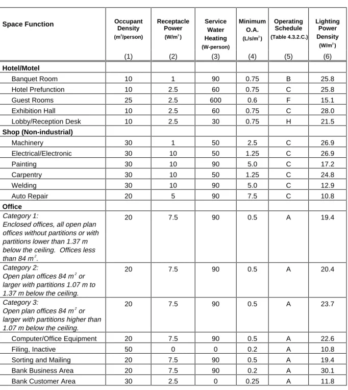
Table 4.3.2.B. Space Functions: Default Assumptions
Space Function Occupant Density (m2 /person) Receptacle Power (W/m2 ) Service Water Heating (W-person) Minimum O.A. (L/s/m2 ) Operating Schedule (Table 4.3.2.C.) Lighting Power Density (W/m2 ) (1) (2) (3) (4) (5) (6) Assembly Auditorium/Exhibit 5 2.5 30 1.5 C 17.2 Religious Worship 5 1 15 1.5 I 26.9 Theater - Performance 7.5 2.5 30 1.0 I 16.2
Theater - Motion Picture 5 2.5 30 1.5 I 16.2
Lobby 10 1 0 1.0 C 10.8
Atria 10 2.5 0 0.5 C 7.5
Recreation/Lounge 10 1 60 3.0 B 7.5
Conference/Meeting 5 1 45 2.0 C 19.4
Indoor Athletics Seating 5 0 30 1.5 I 10.8
Recreational Sports Area 5 1 90 2.0 I 13.0
Professional Sports Area 5 1.5 60 2.0 I 28.0
Locker Room and Shower 10 2.5 0 2.5 * 8.6
Heath/Institutional Dental Suite/Exam 20 10 90 0.4 C 22.6 Emergency 20 10 180 0.75 H 24.7 Laboratory 20 10 180 0.75 H 20.4 Medical Supplies 20 1 0 0.75 H 25.8 Nursery 20 10 90 0.6 H 21.5 Nurse Station 20 2.5 45 0.4 H 22.6 Occupational/Physical Therapy 20 10 45 0.6 C 17.2 Patient Rooms 20 10 90 0.6 H 15.1 Pharmacy 20 2.5 45 0.4 C 18.3 Radiology 20 10 90 0.4 H 22.6 Surgical/O.B. Suites 20 10 180 0.75 H 22.6 Operating Room 20 10 300 0.75 H 75.3 Recovery 20 10 180 0.4 H 24.8
Table 4.3.2.B. Space Functions: Default Assumptions (cont.)
Space Function Occupant Density (m2 /person) Receptacle Power (W/m2 ) Service Water Heating (W-person) Minimum O.A. (L/s/m2 ) Operating Schedule (Table 4.3.2.C.) Lighting Power Density (W/m2 ) (1) (2) (3) (4) (5) (6) Hotel/Motel Banquet Room 10 1 90 0.75 B 25.8 Hotel Prefunction 10 2.5 60 0.75 C 25.8 Guest Rooms 25 2.5 600 0.6 F 15.1 Exhibition Hall 10 2.5 60 0.75 C 28.0 Lobby/Reception Desk 10 2.5 30 0.75 H 21.5 Shop (Non-industrial) Machinery 30 1 50 2.5 C 26.9 Electrical/Electronic 30 10 50 1.25 C 26.9 Painting 30 10 90 5.0 C 17.2 Carpentry 30 10 50 1.25 C 24.8 Welding 30 10 90 5.0 C 12.9 Auto Repair 20 5 90 7.5 C 10.8 Office Category 1:
Enclosed offices, all open plan offices without partitions or with partitions lower than 1.37 m below the ceiling. Offices less than 84 m2
.
20 7.5 90 0.5 A 19.4
Category 2:
Open plan offices 84 m2 or larger with partitions 1.07 m to 1.37 m below the ceiling.
20 7.5 90 0.5 A 20.4
Category 3:
Open plan offices 84 m2 or larger with partitions higher than 1.07 m below the ceiling.
20 7.5 90 0.5 A 23.7
Computer/Office Equipment 20 7.5 90 0.5 A 22.6
Filing, Inactive 50 0 0 0.2 A 10.8
Sorting and Mailing 20 7.5 90 0.5 A 19.4
Bank Business Area 20 7.5 90 0.2 A 30.1
Bank Customer Area 30 2.5 0 0.25 A 11.8
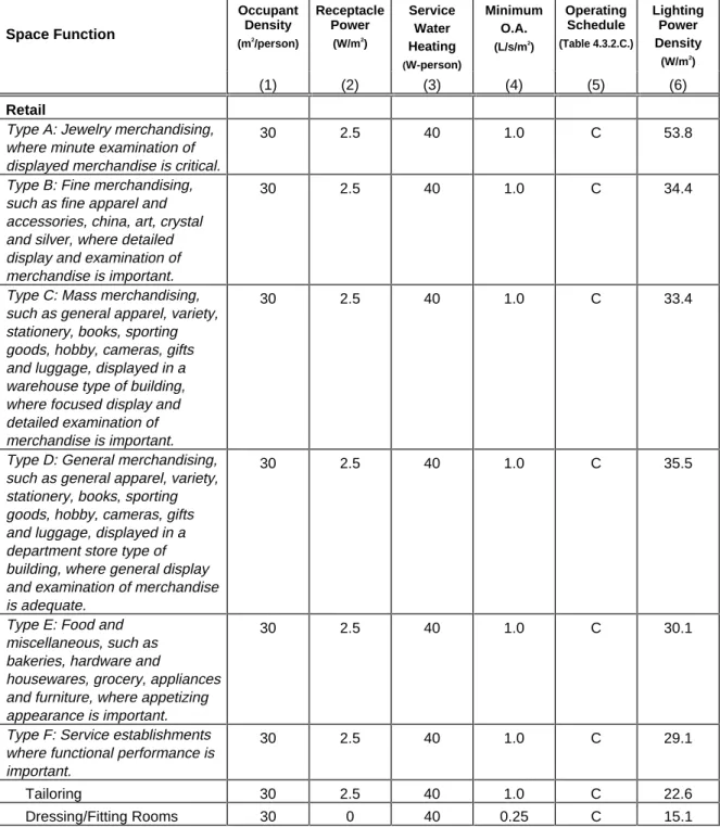
Table 4.3.2.B. Space Functions: Default Assumptions (cont.)
Space Function Occupant Density (m2 /person) Receptacle Power (W/m2 ) Service Water Heating (W-person) Minimum O.A. (L/s/m2 ) Operating Schedule (Table 4.3.2.C.) Lighting Power Density (W/m2 ) (1) (2) (3) (4) (5) (6) RetailType A: Jewelry merchandising, where minute examination of displayed merchandise is critical.
30 2.5 40 1.0 C 53.8
Type B: Fine merchandising, such as fine apparel and accessories, china, art, crystal and silver, where detailed display and examination of merchandise is important.
30 2.5 40 1.0 C 34.4
Type C: Mass merchandising, such as general apparel, variety, stationery, books, sporting goods, hobby, cameras, gifts and luggage, displayed in a warehouse type of building, where focused display and detailed examination of merchandise is important.
30 2.5 40 1.0 C 33.4
Type D: General merchandising, such as general apparel, variety, stationery, books, sporting goods, hobby, cameras, gifts and luggage, displayed in a department store type of building, where general display and examination of merchandise is adequate.
30 2.5 40 1.0 C 35.5
Type E: Food and miscellaneous, such as bakeries, hardware and
housewares, grocery, appliances and furniture, where appetizing appearance is important.
30 2.5 40 1.0 C 30.1
Type F: Service establishments where functional performance is important.
30 2.5 40 1.0 C 29.1
Tailoring 30 2.5 40 1.0 C 22.6
Dressing/Fitting Rooms 30 0 40 0.25 C 15.1
Table 4.3.2.B. Space Functions: Default Assumptions (cont.)
Space Function Occupant Density (m2 /person) Receptacle Power (W/m2 ) Service Water Heating (W-person) Minimum O.A. (L/s/m2 ) Operating Schedule (Table 4.3.2.C.) Lighting Power Density (W/m2 ) (1) (2) (3) (4) (5) (6) Food Service Bar/Lounge 10 1 90 1.5 B 26.9 Leisure Dining 10 1 90 1.0 B 26.9 Fast Food/Cafeteria 10 1 120 1.0 B 14.0 Kitchen 20 10 120 1.5 B 15.1 Dormitory Bedroom 25 2.5 500 0.3 G 11.8 Bedroom/Study 25 2.5 500 0.3 G 15.1 Study Hall 25 2.5 90 0.3 C 19.4 Education Classroom 7.5 5 65 1.0 D 21.5 Library Audio/Visual 20 5 90 0.4 C 11.8Stack - Stack Mounted Lighting
20 0 90 0.4 C 16.2
Stack - Ceiling Lighting 20 0 90 0.4 C 32.3
Card File/Cataloguing 20 2.5 90 0.4 C 17.2 Reading 20 1 90 0.4 C 20.4 Laboratories Laboratories 20 10 180 0.5 A 24.8 Storage/Warehouse Inactive Storage 1750 0 300 0.25 E 3.2
Active Storage, Bulky 100 1 65 0.25 E 3.2
Active Storage, Fine 50 1 65 0.25 E 7.5
Material Handling 20 1 65 0.4 E 10.8
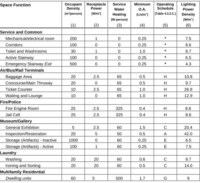
Table 4.3.2.B. Space Functions: Default Assumptions (cont.)
Space Function Occupant Density (m2 /person) Receptacle Power (W/m2 ) Service Water Heating (W-person) Minimum O.A. (L/s/m2 ) Operating Schedule (Table 4.3.2.C.) Lighting Power Density (W/m2 ) (1) (2) (3) (4) (5) (6)
Service and Common
Mechanical/electrical room 200 1 0 0.25 * 7.5
Corridors 100 0 0 0.25 * 8.6
Toilet and Washrooms 30 1 0 1.0 * 8.7
Active Stairway 100 0 0 0.25 * 6.5
Emergency Stairway Exit 500 0 0 0.25 * 4.3
Air/Bus/Rail Terminals
Baggage Area 20 2.5 65 0.5 H 10.8
Concourse/Main Thruway 20 0 65 0.5 H 9.7
Ticket Counter 10 2.5 65 1.0 H 26.9
Waiting and Lounge 10 0 65 1.0 H 12.9
Fire/Police
Fire Engine Room 25 2.5 325 0.4 H 8.6
Jail Cell 25 2.5 325 0.4 H 8.6
Museum/Gallery
General Exhibition 5 2.5 60 1.5 C 20.4
Inspection/Restoration 20 5 50 0.5 A 42.0
Storage (Artifacts) - Inactive 1000 0 60 0.25 E 6.5
Storage (Artifacts) - Active 100 1 60 0.25 E 7.5
Laundry
Washing 20 20 60 0.6 C 9.7
Ironing and Sorting 20 20 60 0.5 C 14.0
Multifamily Residential
Dwelling units 60 5 500 1.7 G 9
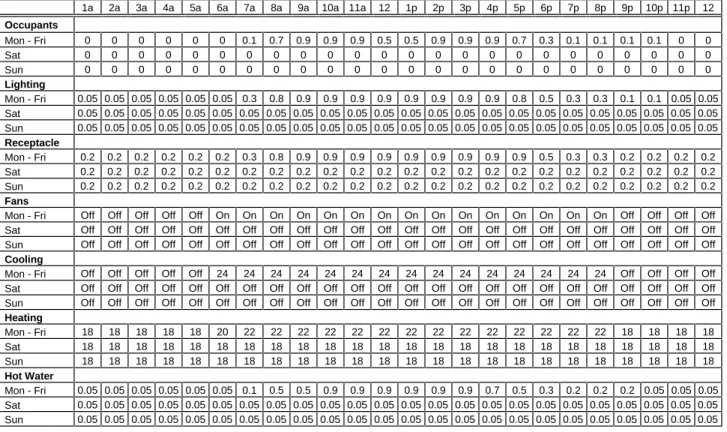
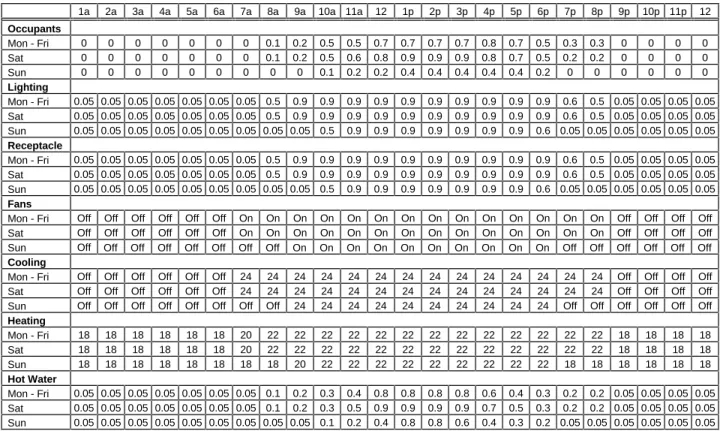
Table 4.3.2.C. Operating Schedule ‘A’
1a 2a 3a 4a 5a 6a 7a 8a 9a 10a 11a 12 1p 2p 3p 4p 5p 6p 7p 8p 9p 10p 11p 12 Occupants Mon - Fri 0 0 0 0 0 0 0.1 0.7 0.9 0.9 0.9 0.5 0.5 0.9 0.9 0.9 0.7 0.3 0.1 0.1 0.1 0.1 0 0 Sat 0 0 0 0 0 0 0 0 0 0 0 0 0 0 0 0 0 0 0 0 0 0 0 0 Sun 0 0 0 0 0 0 0 0 0 0 0 0 0 0 0 0 0 0 0 0 0 0 0 0 Lighting Mon - Fri 0.05 0.05 0.05 0.05 0.05 0.05 0.3 0.8 0.9 0.9 0.9 0.9 0.9 0.9 0.9 0.9 0.8 0.5 0.3 0.3 0.1 0.1 0.05 0.05 Sat 0.05 0.05 0.05 0.05 0.05 0.05 0.05 0.05 0.05 0.05 0.05 0.05 0.05 0.05 0.05 0.05 0.05 0.05 0.05 0.05 0.05 0.05 0.05 0.05 Sun 0.05 0.05 0.05 0.05 0.05 0.05 0.05 0.05 0.05 0.05 0.05 0.05 0.05 0.05 0.05 0.05 0.05 0.05 0.05 0.05 0.05 0.05 0.05 0.05 Receptacle Mon - Fri 0.2 0.2 0.2 0.2 0.2 0.2 0.3 0.8 0.9 0.9 0.9 0.9 0.9 0.9 0.9 0.9 0.9 0.5 0.3 0.3 0.2 0.2 0.2 0.2 Sat 0.2 0.2 0.2 0.2 0.2 0.2 0.2 0.2 0.2 0.2 0.2 0.2 0.2 0.2 0.2 0.2 0.2 0.2 0.2 0.2 0.2 0.2 0.2 0.2 Sun 0.2 0.2 0.2 0.2 0.2 0.2 0.2 0.2 0.2 0.2 0.2 0.2 0.2 0.2 0.2 0.2 0.2 0.2 0.2 0.2 0.2 0.2 0.2 0.2 FansMon - Fri Off Off Off Off Off On On On On On On On On On On On On On On On Off Off Off Off Sat Off Off Off Off Off Off Off Off Off Off Off Off Off Off Off Off Off Off Off Off Off Off Off Off Sun Off Off Off Off Off Off Off Off Off Off Off Off Off Off Off Off Off Off Off Off Off Off Off Off
Cooling
Mon - Fri Off Off Off Off Off 24 24 24 24 24 24 24 24 24 24 24 24 24 24 24 Off Off Off Off Sat Off Off Off Off Off Off Off Off Off Off Off Off Off Off Off Off Off Off Off Off Off Off Off Off Sun Off Off Off Off Off Off Off Off Off Off Off Off Off Off Off Off Off Off Off Off Off Off Off Off
Heating Mon - Fri 18 18 18 18 18 20 22 22 22 22 22 22 22 22 22 22 22 22 22 22 18 18 18 18 Sat 18 18 18 18 18 18 18 18 18 18 18 18 18 18 18 18 18 18 18 18 18 18 18 18 Sun 18 18 18 18 18 18 18 18 18 18 18 18 18 18 18 18 18 18 18 18 18 18 18 18 Hot Water Mon - Fri 0.05 0.05 0.05 0.05 0.05 0.05 0.1 0.5 0.5 0.9 0.9 0.9 0.9 0.9 0.9 0.7 0.5 0.3 0.2 0.2 0.2 0.05 0.05 0.05 Sat 0.05 0.05 0.05 0.05 0.05 0.05 0.05 0.05 0.05 0.05 0.05 0.05 0.05 0.05 0.05 0.05 0.05 0.05 0.05 0.05 0.05 0.05 0.05 0.05 Sun 0.05 0.05 0.05 0.05 0.05 0.05 0.05 0.05 0.05 0.05 0.05 0.05 0.05 0.05 0.05 0.05 0.05 0.05 0.05 0.05 0.05 0.05 0.05 0.05
Table 4.3.2.C. Operating Schedule ‘B’
1a 2a 3a 4a 5a 6a 7a 8a 9a 10a 11a 12 1p 2p 3p 4p 5p 6p 7p 8p 9p 10p 11p 12 Occupants Mon - Fri 0.1 0 0 0 0 0 0 0 0.1 0.2 0.5 0.9 0.8 0.5 0.2 0.2 0.3 0.6 0.9 0.9 0.9 0.6 0.4 0.3 Sat 0.3 0 0 0 0 0 0 0 0.1 0.2 0.5 0.9 0.8 0.5 0.2 0.2 0.3 0.6 0.9 0.9 0.9 0.6 0.6 0.5 Sun 0.3 0 0 0 0 0 0 0 0 0.1 0.4 0.5 0.5 0.4 0.2 0.2 0.2 0.5 0.7 0.7 0.5 0.3 0.1 0.1 Lighting Mon - Fri 0.5 0.1 0.1 0.1 0.1 0.1 0.1 0.1 0.5 0.7 0.9 0.9 0.9 0.9 0.9 0.9 0.9 0.9 0.9 0.9 0.9 0.9 0.9 0.9 Sat 0.5 0.1 0.1 0.1 0.1 0.1 0.1 0.1 0.5 0.7 0.9 0.9 0.9 0.9 0.9 0.9 0.9 0.9 0.9 0.9 0.9 0.9 0.9 0.9 Sun 0.5 0.1 0.1 0.1 0.1 0.1 0.1 0.1 0.1 0.5 0.9 0.9 0.9 0.9 0.9 0.9 0.9 0.9 0.9 0.9 0.9 0.9 0.5 0.5 Receptacle Mon - Fri 0.5 0.1 0.1 0.1 0.1 0.1 0.1 0.1 0.5 0.7 0.9 0.9 0.9 0.9 0.9 0.9 0.9 0.9 0.9 0.9 0.9 0.9 0.9 0.9 Sat 0.5 0.1 0.1 0.1 0.1 0.1 0.1 0.1 0.5 0.7 0.9 0.9 0.9 0.9 0.9 0.9 0.9 0.9 0.9 0.9 0.9 0.9 0.9 0.9 Sun 0.5 0.1 0.1 0.1 0.1 0.1 0.1 0.1 0.1 0.5 0.9 0.9 0.9 0.9 0.9 0.9 0.9 0.9 0.9 0.9 0.9 0.9 0.5 0.5 Fans
Mon - Fri On Off Off Off Off Off Off On On On On On On On On On On On On On On On On On Sat On Off Off Off Off Off Off On On On On On On On On On On On On On On On On On Sun On Off Off Off Off Off Off Off On On On On On On On On On On On On On On Off Off
Cooling
Mon - Fri Off Off Off Off Off Off Off 24 24 24 24 24 24 24 24 24 24 24 24 24 24 24 24 24 Sat Off Off Off Off Off Off Off 24 24 24 24 24 24 24 24 24 24 24 24 24 24 24 24 24 Sun Off Off Off Off Off Off Off Off 24 24 24 24 24 24 24 24 24 24 24 24 24 24 Off Off
Heating
Mon - Fri 22 18 18 18 18 18 18 20 22 22 22 22 22 22 22 22 22 22 22 22 22 22 22 22 Sat 22 18 18 18 18 18 18 20 22 22 22 22 22 22 22 22 22 22 22 22 22 22 22 22
Table 4.3.2.C. Operating Schedule ‘C’
1a 2a 3a 4a 5a 6a 7a 8a 9a 10a 11a 12 1p 2p 3p 4p 5p 6p 7p 8p 9p 10p 11p 12 Occupants Mon - Fri 0 0 0 0 0 0 0 0.1 0.2 0.5 0.5 0.7 0.7 0.7 0.7 0.8 0.7 0.5 0.3 0.3 0 0 0 0 Sat 0 0 0 0 0 0 0 0.1 0.2 0.5 0.6 0.8 0.9 0.9 0.9 0.8 0.7 0.5 0.2 0.2 0 0 0 0 Sun 0 0 0 0 0 0 0 0 0 0.1 0.2 0.2 0.4 0.4 0.4 0.4 0.4 0.2 0 0 0 0 0 0 Lighting Mon - Fri 0.05 0.05 0.05 0.05 0.05 0.05 0.05 0.5 0.9 0.9 0.9 0.9 0.9 0.9 0.9 0.9 0.9 0.9 0.6 0.5 0.05 0.05 0.05 0.05 Sat 0.05 0.05 0.05 0.05 0.05 0.05 0.05 0.5 0.9 0.9 0.9 0.9 0.9 0.9 0.9 0.9 0.9 0.9 0.6 0.5 0.05 0.05 0.05 0.05 Sun 0.05 0.05 0.05 0.05 0.05 0.05 0.05 0.05 0.05 0.5 0.9 0.9 0.9 0.9 0.9 0.9 0.9 0.6 0.05 0.05 0.05 0.05 0.05 0.05 Receptacle Mon - Fri 0.05 0.05 0.05 0.05 0.05 0.05 0.05 0.5 0.9 0.9 0.9 0.9 0.9 0.9 0.9 0.9 0.9 0.9 0.6 0.5 0.05 0.05 0.05 0.05 Sat 0.05 0.05 0.05 0.05 0.05 0.05 0.05 0.5 0.9 0.9 0.9 0.9 0.9 0.9 0.9 0.9 0.9 0.9 0.6 0.5 0.05 0.05 0.05 0.05 Sun 0.05 0.05 0.05 0.05 0.05 0.05 0.05 0.05 0.05 0.5 0.9 0.9 0.9 0.9 0.9 0.9 0.9 0.6 0.05 0.05 0.05 0.05 0.05 0.05 FansMon - Fri Off Off Off Off Off Off On On On On On On On On On On On On On On Off Off Off Off Sat Off Off Off Off Off Off On On On On On On On On On On On On On On Off Off Off Off Sun Off Off Off Off Off Off Off Off On On On On On On On On On On Off Off Off Off Off Off
Cooling
Mon - Fri Off Off Off Off Off Off 24 24 24 24 24 24 24 24 24 24 24 24 24 24 Off Off Off Off Sat Off Off Off Off Off Off 24 24 24 24 24 24 24 24 24 24 24 24 24 24 Off Off Off Off Sun Off Off Off Off Off Off Off Off 24 24 24 24 24 24 24 24 24 24 Off Off Off Off Off Off
Heating Mon - Fri 18 18 18 18 18 18 20 22 22 22 22 22 22 22 22 22 22 22 22 22 18 18 18 18 Sat 18 18 18 18 18 18 20 22 22 22 22 22 22 22 22 22 22 22 22 22 18 18 18 18 Sun 18 18 18 18 18 18 18 18 20 22 22 22 22 22 22 22 22 22 18 18 18 18 18 18 Hot Water Mon - Fri 0.05 0.05 0.05 0.05 0.05 0.05 0.05 0.1 0.2 0.3 0.4 0.8 0.8 0.8 0.8 0.6 0.4 0.3 0.2 0.2 0.05 0.05 0.05 0.05 Sat 0.05 0.05 0.05 0.05 0.05 0.05 0.05 0.1 0.2 0.3 0.5 0.9 0.9 0.9 0.9 0.7 0.5 0.3 0.2 0.2 0.05 0.05 0.05 0.05 Sun 0.05 0.05 0.05 0.05 0.05 0.05 0.05 0.05 0.05 0.1 0.2 0.4 0.8 0.8 0.6 0.4 0.3 0.2 0.05 0.05 0.05 0.05 0.05 0.05
Table 4.3.2.C. Operating Schedule ‘D’
1a 2a 3a 4a 5a 6a 7a 8a 9a 10a 11a 12 1p 2p 3p 4p 5p 6p 7p 8p 9p 10p 11p 12 Occupants Mon - Fri 0 0 0 0 0 0 0 0.1 0.9 0.9 0.9 0.8 0.8 0.8 0.8 0.5 0.2 0.1 0.3 0.3 0.3 0.1 0 0 Sat 0 0 0 0 0 0 0 0 0 0 0 0 0 0 0 0 0 0 0 0 0 0 0 0 Sun 0 0 0 0 0 0 0 0 0 0 0 0 0 0 0 0 0 0 0 0 0 0 0 0 Lighting Mon - Fri 0.05 0.05 0.05 0.05 0.05 0.05 0.05 0.3 0.9 0.9 0.9 0.9 0.9 0.9 0.9 0.7 0.5 0.5 0.7 0.7 0.7 0.3 0.05 0.05 Sat 0.05 0.05 0.05 0.05 0.05 0.05 0.05 0.05 0.05 0.05 0.05 0.05 0.05 0.05 0.05 0.05 0.05 0.05 0.05 0.05 0.05 0.05 0.05 0.05 Sun 0.05 0.05 0.05 0.05 0.05 0.05 0.05 0.05 0.05 0.05 0.05 0.05 0.05 0.05 0.05 0.05 0.05 0.05 0.05 0.05 0.05 0.05 0.05 0.05 Receptacle Mon - Fri 0.05 0.05 0.05 0.05 0.05 0.05 0.05 0.3 0.9 0.9 0.9 0.9 0.9 0.9 0.9 0.7 0.5 0.5 0.7 0.7 0.7 0.3 0.05 0.05 Sat 0.05 0.05 0.05 0.05 0.05 0.05 0.05 0.05 0.05 0.05 0.05 0.05 0.05 0.05 0.05 0.05 0.05 0.05 0.05 0.05 0.05 0.05 0.05 0.05 Sun 0.05 0.05 0.05 0.05 0.05 0.05 0.05 0.05 0.05 0.05 0.05 0.05 0.05 0.05 0.05 0.05 0.05 0.05 0.05 0.05 0.05 0.05 0.05 0.05 Fans
Mon - Fri Off Off Off Off Off Off On On On On On On On On On On On On On On On On Off Off Sat Off Off Off Off Off Off Off Off Off Off Off Off Off Off Off Off Off Off Off Off Off Off Off Off Sun Off Off Off Off Off Off Off Off Off Off Off Off Off Off Off Off Off Off Off Off Off Off Off Off
Cooling
Mon - Fri Off Off Off Off Off Off 24 24 24 24 24 24 24 24 24 24 24 24 24 24 24 24 Off Off Sat Off Off Off Off Off Off Off Off Off Off Off Off Off Off Off Off Off Off Off Off Off Off Off Off Sun Off Off Off Off Off Off Off Off Off Off Off Off Off Off Off Off Off Off Off Off Off Off Off Off
Heating Mon - Fri 18 18 18 18 18 18 20 22 22 22 22 22 22 22 22 22 22 22 22 22 22 22 18 18 Sat 18 18 18 18 18 18 18 18 18 18 18 18 18 18 18 18 18 18 18 18 18 18 18 18 Sun 18 18 18 18 18 18 18 18 18 18 18 18 18 18 18 18 18 18 18 18 18 18 18 18 Hot Water Mon - Fri 0.05 0.05 0.05 0.05 0.05 0.05 0.05 0.5 0.5 0.9 0.9 0.9 0.9 0.9 0.9 0.7 0.3 0.5 0.5 0.5 0.3 0.05 0.05 0.05 Sat 0.05 0.05 0.05 0.05 0.05 0.05 0.05 0.05 0.05 0.05 0.05 0.05 0.05 0.05 0.05 0.05 0.05 0.05 0.05 0.05 0.05 0.05 0.05 0.05 Sun 0.05 0.05 0.05 0.05 0.05 0.05 0.05 0.05 0.05 0.05 0.05 0.05 0.05 0.05 0.05 0.05 0.05 0.05 0.05 0.05 0.05 0.05 0.05 0.05
Table 4.3.2.C. Operating Schedule ‘E’
1a 2a 3a 4a 5a 6a 7a 8a 9a 10a 11a 12 1p 2p 3p 4p 5p 6p 7p 8p 9p 10p 11p 12 Occupants Mon - Fri 0 0 0 0 0 0 0 0.2 0.7 0.9 0.9 0.9 0.9 0.5 0.9 0.8 0.8 0.2 0 0 0 0 0 0 Sat 0 0 0 0 0 0 0 0 0.2 0.2 0.2 0.2 0.1 0.1 0.1 0.1 0 0 0 0 0 0 0 0 Sun 0 0 0 0 0 0 0 0 0 0 0 0 0 0 0 0 0 0 0 0 0 0 0 0 Lighting Mon - Fri 0.05 0.05 0.05 0.05 0.05 0.05 0.05 0.4 0.7 0.9 0.9 0.9 0.9 0.9 0.9 0.9 0.9 0.4 0.05 0.05 0.05 0.05 0.05 0.05 Sat 0.05 0.05 0.05 0.05 0.05 0.05 0.05 0.05 0.5 0.9 0.9 0.9 0.9 0.9 0.7 0.5 0.05 0.05 0.05 0.05 0.05 0.05 0.05 0.05 Sun 0.05 0.05 0.05 0.05 0.05 0.05 0.05 0.05 0.05 0.05 0.05 0.05 0.05 0.05 0.05 0.05 0.05 0.05 0.05 0.05 0.05 0.05 0.05 0.05 Receptacle Mon - Fri 0.05 0.05 0.05 0.05 0.05 0.05 0.05 0.4 0.7 0.9 0.9 0.9 0.9 0.9 0.9 0.9 0.9 0.4 0.05 0.05 0.05 0.05 0.05 0.05 Sat 0.05 0.05 0.05 0.05 0.05 0.05 0.05 0.05 0.5 0.9 0.9 0.9 0.9 0.9 0.7 0.5 0.05 0.05 0.05 0.05 0.05 0.05 0.05 0.05 Sun 0.05 0.05 0.05 0.05 0.05 0.05 0.05 0.05 0.05 0.05 0.05 0.05 0.05 0.05 0.05 0.05 0.05 0.05 0.05 0.05 0.05 0.05 0.05 0.05 FansMon - Fri Off Off Off Off Off Off On On On On On On On On On On On On Off Off Off Off Off Off Sat Off Off Off Off Off Off Off On On On On On On On On On Off Off Off Off Off Off Off Off Sun Off Off Off Off Off Off Off Off Off Off Off Off Off Off Off Off Off Off Off Off Off Off Off Off
Cooling
Mon - Fri Off Off Off Off Off Off 24 24 24 24 24 24 24 24 24 24 24 24 Off Off Off Off Off Off Sat Off Off Off Off Off Off Off 24 24 24 24 24 24 24 24 24 Off Off Off Off Off Off Off Off Sun Off Off Off Off Off Off Off Off Off Off Off Off Off Off Off Off Off Off Off Off Off Off Off Off
Heating Mon - Fri 18 18 18 18 18 18 20 22 22 22 22 22 22 22 22 22 22 22 18 18 18 18 18 18 Sat 18 18 18 18 18 18 18 20 22 22 22 22 22 22 22 22 18 18 18 18 18 18 18 18 Sun 18 18 18 18 18 18 18 18 18 18 18 18 18 18 18 18 18 18 18 18 18 18 18 18 Hot Water Mon - Fri 0.05 0.05 0.05 0.05 0.05 0.05 0.05 0.1 0.4 0.5 0.5 0.7 0.9 0.8 0.7 0.8 0.3 0.05 0.05 0.05 0.05 0.05 0.05 0.05 Sat 0.05 0.05 0.05 0.05 0.05 0.05 0.05 0.05 0.05 0.2 0.2 0.4 0.2 0.2 0.2 0.05 0.05 0.05 0.05 0.05 0.05 0.05 0.05 0.05 Sun 0.05 0.05 0.05 0.05 0.05 0.05 0.05 0.05 0.05 0.05 0.05 0.05 0.05 0.05 0.05 0.05 0.05 0.05 0.05 0.05 0.05 0.05 0.05 0.05
Table 4.3.2.C. Operating Schedule ‘F’
1a 2a 3a 4a 5a 6a 7a 8a 9a 10a 11a 12 1p 2p 3p 4p 5p 6p 7p 8p 9p 10p 11p 12 Occupants Mon - Fri 0.9 0.9 0.9 0.9 0.9 0.9 0.7 0.4 0.4 0.2 0.2 0.2 0.2 0.2 0.2 0.3 0.5 0.5 0.5 0.7 0.7 0.8 0.9 0.9 Sat 0.9 0.9 0.9 0.9 0.9 0.9 0.7 0.5 0.5 0.3 0.3 0.3 0.3 0.3 0.3 0.3 0.3 0.5 0.6 0.6 0.6 0.7 0.7 0.7 Sun 0.7 0.7 0.7 0.7 0.7 0.7 0.7 0.7 0.5 0.5 0.5 0.3 0.3 0.2 0.2 0.2 0.3 0.4 0.4 0.6 0.6 0.8 0.8 0.8 Lighting Mon - Fri 0.2 0.2 0.1 0.1 0.1 0.2 0.4 0.5 0.4 0.4 0.3 0.2 0.2 0.2 0.2 0.2 0.2 0.2 0.6 0.8 0.9 0.8 0.6 0.3 Sat 0.2 0.2 0.1 0.1 0.1 0.1 0.3 0.3 0.4 0.4 0.3 0.2 0.2 0.2 0.2 0.2 0.2 0.2 0.6 0.7 0.7 0.7 0.6 0.3 Sun 0.3 0.3 0.2 0.2 0.2 0.2 0.3 0.4 0.4 0.3 0.3 0.3 0.3 0.2 0.2 0.2 0.2 0.2 0.5 0.7 0.8 0.6 0.5 0.3 Receptacle Mon - Fri 0.2 0.2 0.1 0.1 0.1 0.2 0.4 0.5 0.4 0.4 0.3 0.2 0.2 0.2 0.2 0.2 0.2 0.2 0.6 0.8 0.9 0.8 0.6 0.3 Sat 0.2 0.2 0.1 0.1 0.1 0.1 0.3 0.3 0.4 0.4 0.3 0.2 0.2 0.2 0.2 0.2 0.2 0.2 0.6 0.7 0.7 0.7 0.6 0.3 Sun 0.3 0.3 0.2 0.2 0.2 0.2 0.3 0.4 0.4 0.3 0.3 0.3 0.3 0.2 0.2 0.2 0.2 0.2 0.5 0.7 0.8 0.6 0.5 0.3 Fans Mon - Fri On On On On On On On On On On On On On On On On On On On On On On On On Sat On On On On On On On On On On On On On On On On On On On On On On On On Sun On On On On On On On On On On On On On On On On On On On On On On On On Cooling Mon - Fri 24 24 24 24 24 24 24 24 24 24 24 24 24 24 24 24 24 24 24 24 24 24 24 24 Sat 24 24 24 24 24 24 24 24 24 24 24 24 24 24 24 24 24 24 24 24 24 24 24 24 Sun 24 24 24 24 24 24 24 24 24 24 24 24 24 24 24 24 24 24 24 24 24 24 24 24 Heating Mon - Fri 18 18 18 18 18 18 20 22 22 22 22 22 22 22 22 22 22 22 22 22 22 22 22 22 18 18 18 18 18 18 20 22 22 22 22 22 22 22 22 22 22 22 22 22 22 22 22 22
Table 4.3.2.C. Operating Schedule ‘G’
1a 2a 3a 4a 5a 6a 7a 8a 9a 10a 11a 12 1p 2p 3p 4p 5p 6p 7p 8p 9p 10p 11p 12 Occupants Mon - Fri 0.9 0.9 0.9 0.9 0.9 0.9 0.7 0.4 0.3 0.3 0.3 0.3 0.3 0.3 0.3 0.3 0.5 0.9 0.9 0.9 0.9 0.9 0.9 0.9 Sat 0.9 0.9 0.9 0.9 0.9 0.9 0.7 0.5 0.5 0.5 0.5 0.5 0.5 0.5 0.5 0.5 0.7 0.9 0.9 0.9 0.9 0.9 0.9 0.9 Sun 0.9 0.9 0.9 0.9 0.9 0.9 0.7 0.5 0.5 0.5 0.5 0.5 0.5 0.5 0.5 0.5 0.7 0.9 0.9 0.9 0.9 0.9 0.9 0.9 Lighting Mon - Fri 0 0 0 0 0 0.2 0.5 0.5 0 0 0 0 0 0 0 0 0 0 0.9 0.9 0.9 0.8 0.6 0.3 Sat 0 0 0 0 0 0.2 0.5 0.5 0 0 0 0 0 0 0 0 0 0 0.9 0.9 0.9 0.8 0.6 0.3 Sun 0 0 0 0 0 0.2 0.5 0.5 0 0 0 0 0 0 0 0 0 0 0.9 0.9 0.9 0.8 0.6 0.3 Receptacle Mon - Fri 0.2 0.2 0.2 0.2 0.2 0.2 0.8 0.8 0.4 0.4 0.4 0.4 0.4 0.4 0.4 0.5 0.2 0.9 0.9 0.7 0.5 0.5 0.5 0.3 Sat 0.2 0.2 0.2 0.2 0.2 0.2 0.8 0.8 0.4 0.4 0.4 0.4 0.4 0.4 0.4 0.5 0.2 0.9 0.9 0.7 0.5 0.5 0.5 0.3 Sun 0.2 0.2 0.2 0.2 0.2 0.2 0.8 0.8 0.4 0.4 0.4 0.4 0.4 0.4 0.4 0.5 0.2 0.9 0.9 0.7 0.5 0.5 0.5 0.3 Fans Mon - Fri On On On On On On On On On On On On On On On On On On On On On On On On Sat On On On On On On On On On On On On On On On On On On On On On On On On Sun On On On On On On On On On On On On On On On On On On On On On On On On Cooling Mon - Fri 24 24 24 24 24 24 24 24 24 24 24 24 24 24 24 24 24 24 24 24 24 24 24 24 Sat 24 24 24 24 24 24 24 24 24 24 24 24 24 24 24 24 24 24 24 24 24 24 24 24 Sun 24 24 24 24 24 24 24 24 24 24 24 24 24 24 24 24 24 24 24 24 24 24 24 24 Heating Mon - Fri 18 18 18 18 18 18 20 22 22 22 22 22 22 22 22 22 22 22 22 22 22 22 22 22 Sat 18 18 18 18 18 18 20 22 22 22 22 22 22 22 22 22 22 22 22 22 22 22 22 22 Sun 18 18 18 18 18 18 20 22 22 22 22 22 22 22 22 22 22 22 22 22 22 22 22 22 Hot Water Mon - Fri 0.05 0.05 0.05 0.05 0.05 0.2 0.8 0.7 0.5 0.4 0.2 0.2 0.2 0.3 0.5 0.5 0.7 0.7 0.4 0.4 0.2 0.2 0.1 0.1 Sat 0.05 0.05 0.05 0.05 0.05 0.05 0.2 0.5 0.5 0.5 0.3 0.3 0.3 0.3 0.7 0.9 0.7 0.7 0.6 0.5 0.4 0.3 0.2 0.1 Sun 0.05 0.05 0.05 0.05 0.05 0.05 0.05 0.2 0.3 0.3 0.2 0.2 0.3 0.4 0.5 0.6 0.7 0.4 0.3 0.2 0.2 0.2 0.2 0.1Table 4.3.2.C. Operating Schedule ‘H’
1a 2a 3a 4a 5a 6a 7a 8a 9a 10a 11a 12 1p 2p 3p 4p 5p 6p 7p 8p 9p 10p 11p 12 Occupants Mon - Fri 0.9 0.9 0.9 0.9 0.9 0.9 0.9 0.9 0.9 0.9 0.9 0.9 0.9 0.9 0.9 0.9 0.9 0.9 0.9 0.9 0.9 0.9 0.9 0.9 Sat 0.9 0.9 0.9 0.9 0.9 0.9 0.9 0.9 0.9 0.9 0.9 0.9 0.9 0.9 0.9 0.9 0.9 0.9 0.9 0.9 0.9 0.9 0.9 0.9 Sun 0.9 0.9 0.9 0.9 0.9 0.9 0.9 0.9 0.9 0.9 0.9 0.9 0.9 0.9 0.9 0.9 0.9 0.9 0.9 0.9 0.9 0.9 0.9 0.9 Lighting Mon - Fri 0.9 0.9 0.9 0.9 0.9 0.9 0.9 0.9 0.9 0.9 0.9 0.9 0.9 0.9 0.9 0.9 0.9 0.9 0.9 0.9 0.9 0.9 0.9 0.9 Sat 0.9 0.9 0.9 0.9 0.9 0.9 0.9 0.9 0.9 0.9 0.9 0.9 0.9 0.9 0.9 0.9 0.9 0.9 0.9 0.9 0.9 0.9 0.9 0.9 Sun 0.9 0.9 0.9 0.9 0.9 0.9 0.9 0.9 0.9 0.9 0.9 0.9 0.9 0.9 0.9 0.9 0.9 0.9 0.9 0.9 0.9 0.9 0.9 0.9 Receptacle Mon - Fri 0.9 0.9 0.9 0.9 0.9 0.9 0.9 0.9 0.9 0.9 0.9 0.9 0.9 0.9 0.9 0.9 0.9 0.9 0.9 0.9 0.9 0.9 0.9 0.9 Sat 0.9 0.9 0.9 0.9 0.9 0.9 0.9 0.9 0.9 0.9 0.9 0.9 0.9 0.9 0.9 0.9 0.9 0.9 0.9 0.9 0.9 0.9 0.9 0.9 Sun 0.9 0.9 0.9 0.9 0.9 0.9 0.9 0.9 0.9 0.9 0.9 0.9 0.9 0.9 0.9 0.9 0.9 0.9 0.9 0.9 0.9 0.9 0.9 0.9 Fans Mon - Fri On On On On On On On On On On On On On On On On On On On On On On On On Sat On On On On On On On On On On On On On On On On On On On On On On On On Sun On On On On On On On On On On On On On On On On On On On On On On On On Cooling Mon - Fri 24 24 24 24 24 24 24 24 24 24 24 24 24 24 24 24 24 24 24 24 24 24 24 24 Sat 24 24 24 24 24 24 24 24 24 24 24 24 24 24 24 24 24 24 24 24 24 24 24 24 Sun 24 24 24 24 24 24 24 24 24 24 24 24 24 24 24 24 24 24 24 24 24 24 24 24 Heating Mon - Fri 18 18 18 18 18 18 20 22 22 22 22 22 22 22 22 22 22 22 22 22 22 22 22 22 Sat 18 18 18 18 18 18 20 22 22 22 22 22 22 22 22 22 22 22 22 22 22 22 22 22 Sun 18 18 18 18 18 18 20 22 22 22 22 22 22 22 22 22 22 22 22 22 22 22 22 22 Hot Water Mon - Fri 0.9 0.9 0.9 0.9 0.9 0.9 0.9 0.9 0.9 0.9 0.9 0.9 0.9 0.9 0.9 0.9 0.9 0.9 0.9 0.9 0.9 0.9 0.9 0.9 Sat 0.9 0.9 0.9 0.9 0.9 0.9 0.9 0.9 0.9 0.9 0.9 0.9 0.9 0.9 0.9 0.9 0.9 0.9 0.9 0.9 0.9 0.9 0.9 0.9 Sun 0.9 0.9 0.9 0.9 0.9 0.9 0.9 0.9 0.9 0.9 0.9 0.9 0.9 0.9 0.9 0.9 0.9 0.9 0.9 0.9 0.9 0.9 0.9 0.9
Table 4.3.2.C. Operating Schedule ‘I’
1a 2a 3a 4a 5a 6a 7a 8a 9a 10a 11a 12 1p 2p 3p 4p 5p 6p 7p 8p 9p 10p 11p 12 Occupants Mon - Fri 0 0 0 0 0 0 0 0 0 0 0 0 0 0 0.10 0.10 0.10 0.40 0.80 0.80 0.80 0.60 0.40 0.10 Sat 0 0 0 0 0 0 0 0 0 0.10 0.10 0.10 0.40 0.60 0.80 0.60 0.40 0.20 0.40 0.80 0.80 0.60 0.40 0.10 Sun 0 0 0 0 0 0 0 0.20 0.40 0.80 0.80 0.40 0.20 0 0 0 0 0 0 0 0 0 0 0 Lighting Mon - Fri 0.05 0.05 0.05 0.05 0.05 0.05 0.05 0.05 0.05 0.05 0.05 0.05 0.05 0.05 0.50 0.50 0.50 0.80 0.90 0.90 0.90 0.90 0.90 0.50 Sat 0.05 0.05 0.05 0.05 0.05 0.05 0.05 0.05 0.05 0.50 0.50 0.50 0.80 0.90 0.90 0.90 0.80 0.60 0.80 0.90 0.90 0.90 0.90 0.50 Sun 0.05 0.05 0.05 0.05 0.05 0.05 0.05 0.50 0.90 0.90 0.90 0.90 0.50 0.05 0.05 0.05 0.05 0.05 0.05 0.05 0.05 0.05 0.05 0.05 Receptacle Mon - Fri 0.10 0.10 0.10 0.10 0.10 0.10 0.10 0.10 0.10 0.10 0.10 0.10 0.10 0.10 0.20 0.20 0.20 0.80 0.80 0.80 0.80 0.80 0.80 0.10 Sat 0.10 0.10 0.10 0.10 0.10 0.10 0.10 0.10 0.10 0.20 0.20 0.20 0.80 0.80 0.80 0.80 0.80 0.80 0.80 0.80 0.80 0.80 0.80 0.10 Sun 0.10 0.10 0.10 0.10 0.10 0.10 0.10 0.80 0.80 0.80 0.80 0.80 0.20 0.10 0.10 0.10 0.10 0.10 0.10 0.10 0.10 0.10 0.10 0.10 FansMon - Fri Off Off Off Off Off Off Off Off Off Off Off Off Off On On On On On On On On On On On Sat Off Off Off Off Off Off Off Off Off On On On On On On On On On On On On On On On Sun Off Off Off Off Off Off On On On On On On On Off Off Off Off Off Off Off Off Off Off Off
Cooling
Mon - Fri Off Off Off Off Off Off Off Off Off Off Off Off Off 24 24 24 24 24 24 24 24 24 24 Off Sat Off Off Off Off Off Off Off Off Off 24 24 24 24 24 24 24 24 24 24 24 24 24 24 Off Sun Off Off Off Off Off Off 24 24 24 24 24 24 24 Off Off Off Off Off Off Off Off Off Off Off
Heating Mon - Fri 18 18 18 18 18 18 18 18 18 18 18 18 18 20 22 22 22 22 22 22 22 22 22 18 Sat 18 18 18 18 18 18 18 18 18 20 22 22 22 22 22 22 22 22 22 22 22 22 22 18 Sun 18 18 18 18 18 18 20 22 22 22 22 22 22 18 18 18 18 18 18 18 18 18 18 18 Hot Water Mon - Fri 0.05 0.05 0.05 0.05 0.05 0.05 0.05 0.05 0.05 0.05 0.05 0.05 0.05 0.05 0.20 0.20 0.20 0.40 0.90 0.90 0.90 0.80 0.60 0.20 Sat 0.05 0.05 0.05 0.05 0.05 0.05 0.05 0.05 0.05 0.20 0.20 0.20 0.40 0.80 0.90 0.80 0.60 0.40 0.40 0.90 0.90 0.80 0.60 0.20 Sun 0.05 0.05 0.05 0.05 0.05 0.05 0.05 0.10 0.20 0.40 0.40 0.20 0.10 0.05 0.05 0.05 0.05 0.05 0.05 0.05 0.05 0.05 0.05 0.05
4.3.3. Exceptional Conditions
4.3.3.1. General
1) The compliance shell shall allow the optional
inputs described in Subsection 4.3.3. only for thermal blocks that are “directly conditioned” and for which the space use is one of the space function categories from Table 4.3.2.B. (not “combined”).
2) When exceptional conditions are entered, the
compliance shell shall generate a notice in the output report to alert the building official that this option was chosen and that supporting documentation may be required.
4.3.3.2. Process Heat Gains
1) This is an optional input. The default value is no
process heat gains.
2) If process heat is entered, the compliance shell
shall accept input for:
a) values for maximum sensible and latent heat gain from the process; and
b) sufficient information to define the hourly variation of gains in the form of the schedules in
Table 4.3.2.C.
3) If process heat is entered, the compliance shell
shall replace the default with the input data.
4.3.3.3. Service Water
1) This is an optional input. The default value is
determined by space use classification as described in Subsection 4.3.2.
2) If service water is entered, the compliance shell shall accept input for:
a) value for maximum service water heating load; and
b) sufficient information to define the hourly variation of load in the form of the schedules in
Table 4.3.2.C.
3) If service water is entered, the compliance shell shall replace the default with the input data.
4.3.3.4. Minimum Outdoor Air
1) This is an optional input. The default value is
determined by the space use classification as described in Subsection 4.3.2.
2) If minimum outdoor air flow rate is entered, the
compliance shell shall accept input with the restriction that the value be no less than the default value.
3) If outdoor air flow rate is entered, the compliance
shell shall replace the default with the input data.
4.3.3.5. Space Temperature Schedule
1) This is an optional input. The default value is
determined by the space use classification as described in Subsection 4.3.2.
2) If space temperature schedule is entered, the
compliance shell shall accept input of sufficient information to define the hourly variation of space temperature, in the form given in Table 4.3.2.C.
3) If space temperature schedule is entered, the
compliance shell shall replace the default with the input data.
4.3.3.6. Lighting Area Factor
1) This is an optional input. The default value is 1.0. This is an alternative to permitting input of the lighting power allowance, and is easier to check.
2) If lighting area factor is entered, the compliance
shell shall accept a value with the restriction that it shall be not greater than 1.8.
This is used in defining the reference case (see Chapter 5).
4.3.4. Lighting
1) The compliance shell shall provide a means for
the user to indicate that lighting is not specified in the
proposed design (“lighting not specified”). The compliance shell shall permit this input only when the
space use classification is by building type.
2) If the space use classification by building type is “multifamily residential,” the user shall be prompted to indicate that lighting is not specified in the proposed design (“lighting not specified”), in which case any other input shall be flagged in the report.
This rule is related to
Sentence 4.2.3.2.(1) of the Code, which states that lighting within dwelling units is exempt from allowances and limits on interior lighting power.
This is an optional software capability:
3) The compliance shell shall accept optional input
to identify the lighting as “existing.”
The Code provides for the option of modeling both existing and new components of an addition to an existing building. Some software may not offer this capability.