Publisher’s version / Version de l'éditeur:
Questions? Contact the NRC Publications Archive team at
PublicationsArchive-ArchivesPublications@nrc-cnrc.gc.ca. If you wish to email the authors directly, please see the first page of the publication for their contact information.
https://publications-cnrc.canada.ca/fra/droits
L’accès à ce site Web et l’utilisation de son contenu sont assujettis aux conditions présentées dans le site
LISEZ CES CONDITIONS ATTENTIVEMENT AVANT D’UTILISER CE SITE WEB.
Client Report (National Research Council of Canada. Construction), 2016-02-18
READ THESE TERMS AND CONDITIONS CAREFULLY BEFORE USING THIS WEBSITE. https://nrc-publications.canada.ca/eng/copyright
NRC Publications Archive Record / Notice des Archives des publications du CNRC :
https://nrc-publications.canada.ca/eng/view/object/?id=338ae785-f1e5-4165-a253-1e05baf3ab56 https://publications-cnrc.canada.ca/fra/voir/objet/?id=338ae785-f1e5-4165-a253-1e05baf3ab56
Archives des publications du CNRC
For the publisher’s version, please access the DOI link below./ Pour consulter la version de l’éditeur, utilisez le lien DOI ci-dessous.
https://doi.org/10.4224/23002872
Access and use of this website and the material on it are subject to the Terms and Conditions set forth at
High performance roofing and walls technologies: task 5, parametric
study of curtain wall systems for selection of components and
optimization of thermal performance
Construction
High Performance Roofing and
Walls Technologies
Task 5: Parametric study of Curtain Wall
Systems for Selection of Components and
Optimization of Thermal Performance
Client Report: A1-002844-06
Hamed H. Saber and Michael A. Lacasse
18 February, 2016
HIGH PERFORMANCE WALLS AND ROOFING TECHNOLOGIES NEXT GENERATION TECHNOLOGIES R&D–BUILDING ENVELOPES
REPORT A1-002844.06 i
Table of Contents
Table of Contents ... i
List of Figures ... iii
List of Tables ... ix
Summary ... xi
Acknowledgements ... xiii
1. Introduction ... 1
2. Description of Curtain Wall Components ... 2
2.1 Spandrel Panels ... 3
2.2 Frame ... 3
2.3 Vision Panels ... 3
2.3.1 Vision Glass ... 3
2.3.2 Insulating Glass Unit (IGU) ... 4
3. Overview of Thermal Performance of Enclosed Spaces in IGUs ... 5
3.1 Basic physics of heat transfer across enclosed spaces of IGUs ... 5
4. Approach to Simulation & Description of Curtain Wall Configurations ...10
4.1 Approach for Simulation of NFRC Compliant CW Configurations ...10
4.2 Description of curtain wall panel modelling configurations ...11
4.2.1 Detailed curtain wall manufactured product configuration ...11
4.2.2 Description of curtain wall panel modelling configuration ...11
4.2.3 Description of NFRC curtain wall panel model configuration ...14
5. Results derived from simulation ...16
5.1 Simulation Results for manufactured product configurations ...16
5.1.1 – Results for Double glazed CW product configurations ...16
5.1.2 – Results for Triple glazed CW manufactured product configuration ...19
5.2 Simulation Results for NFRC-Compliant CW configurations ...21
5.2.1 Results for Double-glazed NFRC-Compliant CW Configurations ...21
5.2.2 Results for Triple-glazed NFRC-Compliant CW Configurations ...43
6. Summary ...65
7. References ...66
Appendix 1 ...73
Appendix 2 Results of Simulation of Double-glazed Curtain Wall Manufactured Products ...75
A2.1 Predicted to total heat loss through curtain wall panel derived from simulation ...75
Appendix 3 Results of Simulation of Triple-glazed Curtain Wall Manufacturers Product ...81 Effect of Glazing to Wall Area Ratio / Case-I: 90% Ar and 10% Air, Low-e Coating (ecoat =
0.054) ...81 Effect of Glazing to Wall Area Ratio / Case-II: 90% Kr and 10% Air, Low-e Coating (ecoat =
0.054) ...83 Effect of Glazing to Wall Area Ratio / Case-III: 90% Xe and 10% Air, Low-e Coating (ecoat = 0.054) ...85 Effect of Glazing to Wall Area Ratio / Air, Low-e Coating (ecoat = 0.054) ...87
Effect of Glazing to Wall Area Ratio/Case-IV: Air filled IGU; Low-e Coating vs. no Coating (ecoat=0.054 /e ...89
Effect of Glazing to Wall Area Ratio/Case-IV: 90 % Ar, 10 % Air-filled IGU; Low-e Coating vs. no Coating (ecoat=0.054 /e ...91
Effect of Glazing to Wall Area Ratio/Case-IV: 90 % Kr, 10 % Air-filled IGU; Low-e Coating vs. no Coating (ecoat=0.054 /e ...93
Effect of Glazing to Wall Area Ratio/Case-IV: 90 % Xe, 10 % Air-filled IGU; Low-e Coating vs. no Coating (ecoat=0.054 /e ...95
Effect of Coating (ecoat = 0 – 0.84), 90 % Ar, 10 % Air-filled IGU; Solid Symbols: Epsylon CW
having triple-glazed vision and spandrel panel ...97 Effect of Coating (ecoat = 0 – 0.84), 90 % Kr, 10 % Air-filled IGU; Solid Symbols: Epsylon CW
having triple-glazed vision and spandrel panel ...99 Effect of Coating (ecoat = 0 – 0.84), 90 % Xe, 10 % Air-filled IGU; Solid Symbols: Epsylon
CW having triple-glazed vision and spandrel panel ... 101 Effect of Coating (ecoat = 0 – 0.84), Air-filled IGU; Solid Symbols: Epsylon CW having
triple-glazed vision and spandrel panel ... 103 Appendix 4 Effect of Inclination Angle and Direction of Heat Flow... 111 Appendix 5 - Summary of Previous Model Benchmarking ... 123
HIGH PERFORMANCE WALLS AND ROOFING TECHNOLOGIES NEXT GENERATION TECHNOLOGIES R&D–BUILDING ENVELOPES
REPORT A1-002844.06 iii
List of Figures
Figure 1. Basic components of a typical curtain wall system [6] ... 2
Figure 2. Components of a standard double-glazed insulating glass unit ... 4
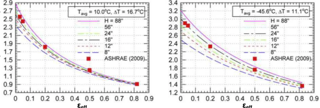
Figure 3 - Dependence of R-value (ft2hr°F/BTU) on effective emissivity, εeff given values of Tavg/ΔT (10 °C/ΔT = 16.7 °C; -45.6 °C/ΔT = 11.1 °C), and different values of H for an airspace of depth 13 mm; ... 9
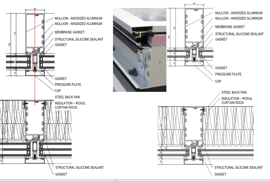
Figure 4. Schematics of enclosed space with and without thin sheet of low emissivity on both sides, placed in the middle of the space of Insulating Glass Units (IGUs). ... Error! Bookmark not defined. Figure 5 – Sectional drawings of triple-glazed curtain wall mullion at vision panel; Sectional drawing of triple-glazed curtain wall mullion at opaque panel ... 1
Figure 6 – Sectional drawing of double-glazed curtain wall mullion; Photo showing end portion of horizontal section; Sectional drawing of double-glazed curtain wall mullion at opaque panel ... 1
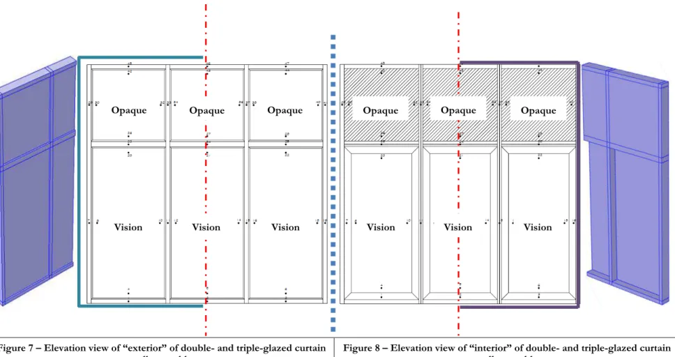
Figure 7 – Elevation view of “exterior” of double- and triple-glazed curtain wall assembly ... 2
Figure 8 – Elevation view of “interior” of double- and triple-glazed curtain wall assembly ... 2
Figure 9 - Reference Curtain Wall assembly conforming to NFRC (2m x 2m vision; 2 m x 1.2 m spandrel) ... 14
Figure 10 - Double Glazing (2G) Curtain Wall sectional views; Surface 2 with low-e of emissivity = 0.054; Other surfaces (1, 3, 4) emissivity = 0.84; Filling gas: 90% gas and 10% air ... 15
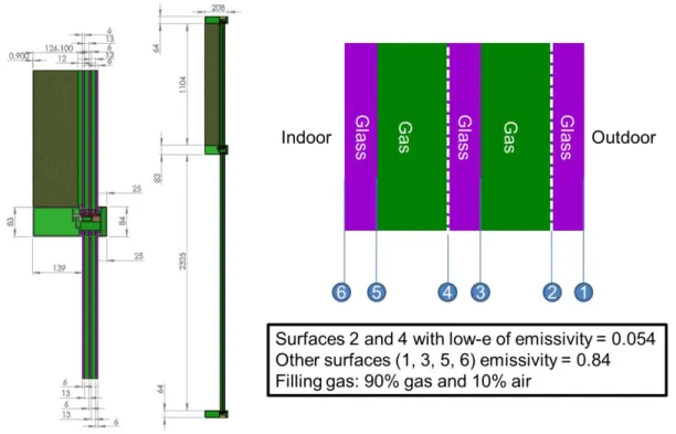
Figure 11 - Triple Glazing (3G) Curtain Wall sectional views and detail of IGU and characteristic surfaces ... 15
Figure 12 – Risk of Condensation on Interior Surface of CW components for NFRC test conditions; Two Options: Option B: ASHRAE 160 (40% RH); Option D: Modified ASHRAE 160 (32% RH) ... 17
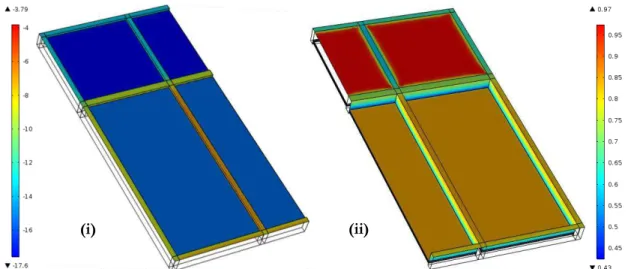
Figure 13 – Simulated exterior temperature (i) and values of temperature index TIndex (ii) of double-glazed thermally broken CW product having IGU with 90% Ar & 10% Air; Surface 2, Ecoat = 0.054. ... 18
Figure 14 – Simulated results of relative humidity on interior surface of double-glazed IGU thermally broken CW product; (i) Option D: Modified ASHRAE 160 (32% RH); (ii) Option B: ASHRAE 160 (40% RH) ... 18
Figure 15 – Simulated results of temperature difference ( ) on exterior surface of double-glazed CW product: (i) Option D: Modified ASHRAE 160 (32% RH); (ii) Option B: ASHRAE 160 (40% RH) ... 18
Figure 16 – Simulated temperature differences between surface ( TInt) and dew point (TDewpoint) of double-glazed thermally broken CW product having IGU with 90% Ar & 10% Air; Surface 2, Ecoat = 0.054. ... 19
Figure 17 – Simulated exterior temperature (i) and values of temperature index TIndex (ii) of triple-glazed thermally broken CW product having IGU with 90% Ar & 10% Air; Surface 2, Ecoat = 0.054. ... 20
Figure 18 – Simulated results of relative humidity on interior surface of triple -glazed IGU thermally broken CW product; (i) Option D: Modified ASHRAE 160 (32% RH); (ii) Option B: ASHRAE 160 (40% RH) ... 20
Figure 19 – Simulated results of temperature difference ( ) on exterior surface of triple-glazed CW product: (i) Option D: Modified ASHRAE 160 (32% RH); (ii) Option B: ASHRAE 160 (40% RH) ... 20
Figure 20 – Simulated temperature differences between surface ( TInt) and dew point (TDewpoint) of triple-glazed thermally broken CW product having IGU with 90% Ar & 10% Air; Surface 2, Ecoat = 0.054. ... 21
Figure 21 – Simulated exterior (i) & interior (ii) temperature; values of temperature index TIndex (iii) of double-glazed thermally broken NFRC-compliant CW having IGU with 90% Ar & 10% Air. ... 23
Figure 22 – Simulated results of RH on interior surface of double-glazed IGU thermally broken NFRC-compliant CW; (i) Option D: Modified ASHRAE 160 (32% RH); (ii) Option B: ASHRAE 160 (40% RH) ... 23
Figure 23 – Simulated results of temperature difference on exterior surface of double-glazed NFRC-compliant CW: (i) Option D: Modified ASHRAE 160 (32% RH); (ii) Option B: ASHRAE 160 (40% RH) ... 23
Figure 24 – Simulated temperature differences between surface and dew point (TDewpoint) of double-glazed thermally broken NFRC compliant CW having IGU with 90% Ar & 10% Air; Surface 2, Ecoat = 0.054 ... 24
Figure 25 - Predicted (by simulation) R-value (i) and U-value (ii) (air-to-air; surface-to-surface) of double-glazed low-e coatlow-ed (low-e = 0.054) thlow-ermally broklow-en curtain wall slow-ection in rlow-elation to glazing to Wall Arlow-ea Ratio . 26 Figure 26 - Predicted (by simulation) R-value (i) & U-value (ii) (air-to-air; surface-to-surface) of double-glazed low-e coated (e = 0.054) thermally broken curtain wall section in relation to glazing to Wall Area Ratio ... 26
Figure 27- Predicted (by simulation) R-value (i) and U-value (ii) (air-to-air; surface-to-surface) of double-glazed low-e coated (e = 0.054) thermally broken curtain wall section in relation to glazing to Wall Area Ratio .... 27
Figure 28 - Predicted (by simulation) R-value (i) and U-value (ii) (air-to-air; surface-to-surface) of double-glazed low-e coatlow-ed (low-e = 0.054) thlow-ermally broklow-en curtain wall slow-ection in rlow-elation to glazing to Wall Arlow-ea Ratio . 27 Figure 29 - Predicted (by simulation) R-value (i) and U-value (ii) (air-to-air; surface-to-surface) of double-glazed low-e coatlow-ed or not coatlow-ed thlow-ermally broklow-en CW in rlow-elatn to Glazng to Wall Area Ratio ... 28
Figure 30 - Predicted (by simulation) R-value (i) and U-value (ii) (air-to-air; surface-to-surface) of double-glazed low-e coatlow-ed or not coatlow-ed thlow-ermally broklow-en CW in rlow-elatn to Glazng to Wall Area Ratio ... 28
Figure 31 - Predicted (by simulation) R-value (i) ; U-value (ii) (air-to-air; surface-to-surface) of double-glazed, low-e thermally broken curtain wall in relation to Glazing to Wall Area Ratio ... 29
Figure 32 - Predicted (by simulation) R-value (i) ; U-value (ii) (air-to-air; surface-to-surface) of double-glazed, low-e thermally broken curtain wall in relation to Glazing to Wall Area Ratio ... 29
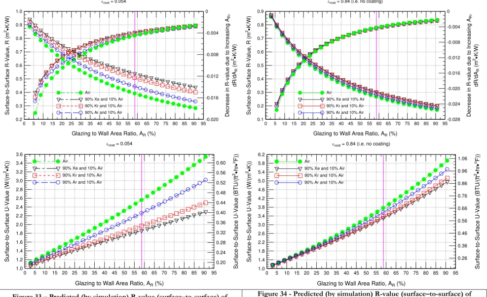
Figure 33 – Predicted (by simulation) R-value (surface–to-surface) of double-glazed low-e coated (e = 0.054)
thermally broken curtain wall in relation to Glazing to Wall Area Ratio for IGU filled with 100 % Air; 90 % Ar, 10 % Air; 90 % Kr, 10 % Air; 90 % Xe, 10 % Air ... 30
Figure 34 - Predicted (by simulation) R-value (surface–to-surface) of double-glazed low-e coated (e = 0.054)
thermally broken curtain wall in relation to glazing to Wall Area Ratio for IGU filled with 100 % Air; 90 % Ar, 10 % Air; 90 % Kr, 10 % Air; 90 % Xe, 10 % Air ... 30 Figure 35 – Predicted (by simulation) R-value (i) ; U-value (ii) of double-glazed, thermally broken curtain wall as a
function of coating emissivity for IGU filled with 90% Ar & 10 % Air ... 32 Figure 36 - Predicted (by simulation) R-value (i) ; U-value (ii) of double-glazed, thermally broken curtain wall as a
function of coating emissivity for IGU filled with 90% Kr and 10 % Air ... 32 Figure 37 - Predicted (by simulation) R-value (i); U-value (ii) (air-to-air; surface-to-surface) of double-glazed,
thermally broken curtain wall as a function of coating emissivity ... 33 Figure 38 - Predicted (by simulation) R-value (i) ; U-value (ii) (air-to-air; surface-to-surface) of double-glazed,
thermally broken curtain wall as a function of coating emissivity ... 33 Figure 39 – Predicted (by simulation) (i) R-value (surface-to-surface) as a function of coating emissivity (surface S2)
and; (ii) rate of change in R-value in relation to emissivity for a NFRC-compliant, thermally-broken Curtain Wall, with a double-glazed, Air-, Ar-, Xe-, or Kr-filled IGU... 34 Figure 40 – Predicted (by simulation) (i) U-value (surface-to-surface) as a function of coating emissivity (surface S2)
and; (ii) rate of change in U-value in relation to emissivity for a NFRC-compliant, thermally-broken Curtain Wall, with a double-glazed, Air-, Ar-, Xe-, or Kr-filled IGU... 34 Figure 41 – Predicted (by simulation) (i) R-value and (ii) U-value (air-to-air; surface-to-surface) as a function of
Spandrel panel insulation for a NFRC-compliant, thermally-broken double-glazed Ar-filled IGU curtain wall assembly with and without low-e coating on surface 2 ... 36 Figure 42 – Predicted (by simulation) (i) R-value and (ii) U-value (air-to-air; surface-to-surface) as a function of
Spandrel panel insulation for a NFRC-compliant, thermally-broken double-glazed Kr-filled IGU curtain wall assembly with and without low-e coating on surface 2 ... 36
Figure 43 – Predicted (by simulation) (i) R-value and (ii) U-value (air-to-air; surface-to-surface) as a function of
Spandrel panel insulation for a NFRC-compliant, thermally-broken double-glazed Xe-filled IGU curtain wall assembly with and without low-e coating on surface 2 ... 37 Figure 44 – Predicted (by simulation) (i) R-value and (ii) U-value (air-to-air; surface-to-surface) as a function of
Spandrel panel insulation for a NFRC-compliant, thermally-broken double-glazed Air filled IGU curtain wall assembly with and without low-e coating on surface 2 ... 37
Figure 45 – Predicted (by simulation) (i) R-value and (ii) U-value as a function of Spandrel panel insulation for a
NFRC-compliant, thermally-broken double-glazed curtain wall assembly incorporating an IGU with
low-ε coating (surface 2) and filled with either Ar, Kr, Xe, or Air ... 38
Figure 46 – Predicted (by simulation) (i) R-value and (ii) U-value as a function of Spandrel panel insulation for a NFRC-compliant, thermally-broken double-glazed curtain wall assembly incorporating an IGU without low-ε coating (surface 2) and filled with either Ar, Kr, Xe, or Air ... 38 Figure 47 - Typical doubled & triple-glazed IGUs and their respective components ... 39
Figure 48 – Predicted (by simulation) (i) R-value and (ii) U-value (air-to-air; surface-to-surface) as a function of
thermal conductivity of spacer for a NFRC-compliant, thermally-broken double-glazed Ar-filled IGU curtain wall assembly with and without low-e coating on surface 2 ... 40 Figure 49 – Predicted (by simulation) (i) R-value and (ii) U-value (air-to-air; surface-to-surface) as a function of
thermal conductivity of spacer for a NFRC-compliant, thermally-broken double-glazed Kr-filled IGU curtain wall assembly with and without low-e coating on surface 2 ... 40
Figure 50 – Predicted (by simulation) (i) R-value and (ii) U-value (air-to-air; surface-to-surface) as a function of
thermal conductivity of spacer for a NFRC-compliant, thermally-broken double-glazed Xe-filled IGU curtain wall assembly with and without low-e coating on surface 2 ... 41 Figure 51 – Predicted (by simulation) (i) R-value and (ii) U-value (air-to-air; surface-to-surface) as a function of
thermal conductivity of spacer for a NFRC-compliant, thermally-broken double-glazed Air filled IGU curtain wall assembly with and without low-e coating on surface 2 ... 41
Figure 52 – Predicted (by simulation) R-value (surface-to-surface) as a function of thermal conductivity of Spacer
for a NFRC-compliant, thermally-broken double-glazed curtain wall assembly incorporating an IGU
with low-ε coating (ε = 0.054; surface 2) and filled with either Ar, Kr, Xe, or Air ... 42
Figure 53 – Predicted (by simulation) (i) R-value (surface-to-surface) as a function of thermal conductivity of Spacer
for a NFRC-compliant, thermally-broken double-glazed curtain wall assembly incorporating an IGU without low-ε coating and filled with either Ar, Kr, Xe, or Air ... 42
Figure 54 – Simulated exterior (i) & interior (ii) temperature; values of temperature index TIndex (iii) of triple-glazed
HIGH PERFORMANCE WALLS AND ROOFING TECHNOLOGIES NEXT GENERATION TECHNOLOGIES R&D–BUILDING ENVELOPES
REPORT A1-002844.06 v
Figure 55 – Simulated results of RH on interior surface of triple-glazed IGU thermally broken NFRC-compliant CW;
(i) Option D: Modified ASHRAE 160 (32% RH); (ii) Option B: ASHRAE 160 (40% RH) ... 44
Figure 56 – Simulated results of temperature difference ( ) on exterior surface of triple-glazed NFRC-compliant
CW: (i) Option D: Modified ASHRAE 160 (32% RH); (ii) Option B: ASHRAE 160 (40% RH) ... 44
Figure 57 – Simulated temperature differences between surface ( TInt) and dew point (TDewpoint) of triple-glazed
thermally broken NFRC compliant CW having IGU with 90% Ar & 10% Air; ... 45 Figure 58 – Predicted (by simulation) (i) R-value and (ii) U-value (air-to-air; surface–to-surface) of triple-glazed low-e
(e = 0.054) coated thermally broken Curtain Wall in relation to Glazing to Wall Area Ratio for IGU filled with 90 % Ar, 10% Air ... 48
Figure 59 – Predicted (by simulation) (i) R-value and (ii) U-value (air-to-air; surface–to-surface) of triple-glazed low-e
(e = 0.054) coated thermally broken Curtain Wall in relation to Glazing to Wall Area Ratio for IGU filled with 90 % Kr, 10% Air ... 48 Figure 60 – Predicted (by simulation) (i) R-value and (ii) U-value (air-to-air; surface–to-surface) of triple-glazed low-e
(e = 0.054) coated thermally broken Curtain Wall in relation to Glazing to Wall Area Ratio for IGU filled with 90 % Xe, 10% Air ... 49
Figure 61 – Predicted (by simulation) (i) R-value and (ii) U-value (air-to-air; surface–to-surface) of triple-glazed low-e
(e = 0.054) coated thermally broken Curtain Wall in relation to Glazing to Wall Area Ratio for IGU filled with 100 % Air ... 49 Figure 62 – Predicted (by simulation) (i) R-value and (ii) U-value (air-to-air; surface–to-surface) of triple-glazed low-e (e = 0.054) or no low-e (e = 0.84) coated thermally broken Curtain Wall in relation to Glazing to Wall Area Ratio for IGU filled with 90 % Ar, 10% Air ... 50
Figure 63 – Predicted (by simulation) (i) R-value and (ii) U-value (air-to-air; surface–to-surface) of triple-glazed low-e
(e = 0.054) or no low-e (e = 0.84) coated thermally broken Curtain Wall in relation to Glazing to Wall Area Ratio for IGU filled with 90 % Kr, 10% Air ... 50
Figure 64 – Predicted (by simulation) (i) R-value and (ii) U-value (air-to-air; surface–to-surface) of triple-glazed low-e
(e = 0.054) or no low-e (e = 0.84) coated thermally broken Curtain Wall in relation to Glazing to Wall Area Ratio for IGU filled with 90 % Xe, 10% Air ... 51 Figure 65 – Predicted (by simulation) (i) R-value and (ii) U-value (air-to-air; surface–to-surface) of triple-glazed low-e (e = 0.054) or no low-e (e = 0.84) coated thermally broken Curtain Wall in relation to Glazing to Wall Area Ratio for IGU filled with 100 % Air ... 51
Figure 66 – Predicted (by simulation) (i) R-value and rate of change in R-value in relation to emissivity and; (ii)
U-value (surface-to-surface) as a function of Glazing to Wall Area Ratio, for a NFRC-compliant, thermally-broken Curtain Wall, having a triple-glazed, low-e coated Air-, Ar-, Xe-, or Kr-filled IGU . 52 Figure 67 – Predicted (by simulation) (i) R-value and rate of change in R-value in relation to emissivity and; (ii)
U-value (surface-to-surface) as a function of Glazing to Wall Area Ratio, for a NFRC-compliant, thermally-broken Curtain Wall, having a triple-glazed, Air-, Ar-, Xe-, or Kr-filled IGU (no low-e coating; e = 0.84) ... 52 Figure 68 – Predicted (by simulation) R-value (i) ; U-value (ii) of triple-glazed, thermally broken curtain wall as a
function of coating emissivity for IGU filled with 90% Ar and 10 % Air ... 54 Figure 69 – Predicted (by simulation) R-value (i) ; U-value (ii) of triple -glazed, thermally broken curtain wall as a
function of coating emissivity for IGU filled with 90% Kr and 10 % Air ... 54
Figure 70 – Predicted (by simulation) R-value (i) ; U-value (ii) of triple-glazed, thermally broken curtain wall as a
function of coating emissivity for IGU filled with 90% Xe and 10 % Air ... 55
Figure 71 – Predicted (by simulation) R-value (i) ; U-value (ii) of triple -glazed, thermally broken curtain wall as a
function of coating emissivity for IGU filled with 100 % Air ... 55
Figure 72 – Predicted (by simulation) (i) R-value (surface-to-surface) as a function of coating emissivity (surface S2)
and; (ii) rate of change in R-value in relation to emissivity for a NFRC-compliant, thermally-broken Curtain Wall, with a triple-glazed, Air-, Ar-, Xe-, or Kr-filled IGU ... 56 Figure 73 – Predicted (by simulation) (i) U-value (surface-to-surface) as a function of coating emissivity (surface S2)
and; (ii) rate of change in U-value in relation to emissivity for a NFRC-compliant, thermally-broken Curtain Wall, with a triple-glazed, Air-, Ar-, Xe-, or Kr-filled IGU ... 56
Figure 74 – Predicted (by simulation) (i) R-value and (ii) U-value (air-to-air; surface-to-surface) as a function of
Spandrel panel insulation for a NFRC-compliant, thermally-broken triple-glazed Ar-filled IGU curtain wall assembly with and without low-e coating on surface 2 ... 58 Figure 75 – Predicted (by simulation) (i) R-value and (ii) U-value (air-to-air; surface-to-surface) as a function of
Spandrel panel insulation for a NFRC-compliant, thermally-broken triple-glazed Kr-filled IGU curtain wall assembly with and without low-e coating on surface 2 ... 58
Figure 76 – Predicted (by simulation) (i) R-value and (ii) U-value (air-to-air; surface-to-surface) as a function of
Spandrel panel insulation for a NFRC-compliant, thermally-broken triple-glazed Xe-filled IGU curtain wall assembly with and without low-e coating on surface 2 ... 59
Figure 77 – Predicted (by simulation) (i) R-value and (ii) U-value (air-to-air; surface-to-surface) as a function of Spandrel panel insulation for a NFRC-compliant, thermally-broken triple-glazed Air filled IGU curtain wall assembly with and without low-e coating on surface 2 ... 59
Figure 78 – Predicted (by simulation) (i) R-value and (ii) U-value (air-to-air; surface-to-surface) as a function of
Spandrel panel insulation for a NFRC-compliant, thermally-broken triple-glazed curtain wall
assembly incorporating an IGU with low-ε coating and filled with either Ar, Kr, Xe, or Air ... 60
Figure 79 – Predicted (by simulation) (i) R-value and (ii) U-value (air-to-air; surface-to-surface) as a function of Spandrel panel insulation for a NFRC-compliant, thermally-broken triple-glazed curtain wall
assembly incorporating an IGU without low-ε coating and filled with either Ar, Kr, Xe, or Air ... 60
Figure 80 – Predicted (by simulation) (i) R-value and (ii) U-value (air-to-air; surface-to-surface) as a function of
thermal conductivity of spacer for a NFRC-compliant, thermally-broken triple-glazed Ar-filled IGU curtain wall assembly with and without low-e coating on surface 2 ... 62 Figure 81 – Predicted (by simulation) (i) R-value and (ii) U-value (air-to-air; surface-to-surface) as a function of
thermal conductivity of spacer for a NFRC-compliant, thermally-broken triple-glazed Kr-filled IGU curtain wall assembly with and without low-e coating on surface 2 ... 62
Figure 82 – Predicted (by simulation) (i) R-value and (ii) U-value (air-to-air; surface-to-surface) as a function of
thermal conductivity of spacer for a NFRC-compliant, thermally-broken triple-glazed Xe-filled IGU curtain wall assembly with and without low-e coating on surface 2 ... 63 Figure 83 – Predicted (by simulation) (i) R-value and (ii) U-value (air-to-air; surface-to-surface) as a function of
thermal conductivity of spacer for a NFRC-compliant, thermally-broken triple-glazed Air filled IGU curtain wall assembly with and without low-e coating on surface 2 ... 63
Figure 84 – Predicted (by simulation) R-value (surface-to-surface) as a function of thermal conductivity of Spacer for
a NFRC-compliant, thermally-broken triple-glazed curtain wall assembly incorporating an IGU with low-ε coating (ε = 0.054; surface 2) and filled with either Ar, Kr, Xe, or Air ... 64
Figure 85 – Predicted (by simulation) (i) R-value (surface-to-surface) as a function of thermal conductivity of Spacer
for a NFRC-compliant, thermally-broken triple-glazed curtain wall assembly incorporating an IGU
without low-ε coating and filled with either Ar, Kr, Xe, or Air ... 64
Figure 86 – Summary of Thermal performance of NFRC compliant double- and triple-glazed CW assemblies ... 65
Figure A87 – Predicted (by simulation) R-value (surface-to-surface) of double-glazed thermally broken curtain wall
panel in relation to fraction (by volume) of air present in the low-e (0.054) IGUs ... 76
Figure A88 – Predicted (by simulation) R-value (air-to-air) of double-glazed thermally broken curtain wall panel in
relation to fraction (by volume) of air present in the low-e (0.054) IGUs ... 76 Figure A89 - Predicated (by simulation) U-value (surface -to-surface) of double-glazed thermally broken curtain wall
panel in relation to fraction (by volume) of air present in the low-e (0.054) IGUs ... 77
Figure A90 – Predicated (by simulation) U-value (air-to-air) of double-glazed thermally broken curtain wall panel in
relation to fraction (by volume) of air present in the low-e (0.054) IGUs ... 77 Figure A91 - Predicated (by simulation) total heat loss through double-glazed thermally broken curtain wall panel in
relation to fraction (by volume) of air present in the low-e IGUs; red marker shows test value ... 78 Figure A92 - Predicted (by simulation) R-value (surface-to-surface) of double-glazed thermally broken curtain wall
panel in relation to glazing emissivity on surface 2 of IGUs; 90% Ar filled IGU ... 78 Figure A93 - Predicted (by simulation) U-value (surface-to-surface) of double-glazed thermally broken curtain wall
panel in relation to glazing emissivity on surface 2 of IGUs; 90% Ar filled IGU ... 79 Figure A94 - Predicted (by simulation) R-value (air-to-air) of double-glazed thermally broken curtain wall panel in
relation to glazing emissivity on surface 2 of IGUs; 90% Ar filled IGU ... 79 Figure A95 - Predicted (by simulation) U-value (air-to-air) of double-glazed thermally broken curtain wall panel in
relation to glazing emissivity on surface 2 of IGUs; 90% Ar filled IGU ... 80 Figure A96 - Predicted (by simulation) R-value of triple-glazed low-e coated (e = 0.054) thermally broken curtain
wall panel in relation to glazing to Wall Area Ratio; 90% Ar filled IGU ... 81 Figure A97 - Predicted (by simulation) R-value of triple-glazed low-e coated (e = 0.054) thermally broken curtain
wall panel in relation to glazing to Wall Area Ratio; 90% Ar filled IGU ... 81 Figure 98 - Predicted (by simulation) U-value of triple-glazed low-e coated (e = 0.054) thermally broken curtain wall
panel in relation to glazing to Wall Area Ratio; 90% Ar filled IGU ... 82 Figure 99 - Predicted (by simulation) U-value of triple-glazed low-e coated (e = 0.054) thermally broken curtain wall panel in relation to glazing to Wall Area Ratio; 90% Ar filled IGU ... 82 Figure A100 – Predicted (by simulation) R-value of triple-glazed low-e coated (e = 0.054) thermally broken curtain
wall panel in relation to glazing to Wall Area Ratio; 90% Kr filled IGU ... 83 Figure A101 - Predicted (by simulation) R-value of triple-glazed low-e coated (e = 0.054) thermally broken curtain
wall panel in relation to glazing to Wall Area Ratio; 90% Kr filled IGU ... 83 Figure A102 - Predicted (by simulation) U-value of triple-glazed low-e coated (e = 0.054) thermally broken curtain
wall panel in relation to glazing to Wall Area Ratio; 90% Kr filled IGU ... 84 Figure A103 - Predicted (by simulation) U-value of triple-glazed low-e coated (e = 0.054) thermally broken curtain
HIGH PERFORMANCE WALLS AND ROOFING TECHNOLOGIES NEXT GENERATION TECHNOLOGIES R&D–BUILDING ENVELOPES
REPORT A1-002844.06 vii
Figure A104 - Predicted (by simulation) R-value of triple-glazed low-e coated (e = 0.054) thermally broken curtain wall panel in relation to glazing to Wall Area Ratio; 90% Xe filled IGU... 85 Figure A105 - Predicted (by simulation) R-value of triple-glazed low-e coated (e = 0.054) thermally broken curtain
wall panel in relation to glazing to Wall Area Ratio; 90% Xe filled IGU... 85 Figure A106 - Predicted (by simulation) U-value of triple-glazed low-e coated (e = 0.054) thermally broken curtain
wall panel in relation to glazing to Wall Area Ratio; 90% Xe filled IGU... 86 Figure 107 - Predicted (by simulation) U-value of triple-glazed low-e coated (e = 0.054) thermally broken curtain
wall panel in relation to glazing to Wall Area Ratio; 90% Xe filled IGU... 86 Figure A108 - Predicted (by simulation) R-value (air-to-air; surface-to-surface) of triple-glazed low-e coated (e =
0.054) thermally broken curtain wall panel in relation to glazing to Wall Area Ratio; Air filled IGU ... 87 Figure A109 - Predicted (by simulation) R-value (air-to-air; surface-to-surface) of triple-glazed low-e coated (e =
0.054) thermally broken curtain wall panel in relation to glazing to Wall Area Ratio; Air filled IGU ... 87 Figure A110 - Predicted (by simulation) U-value (air-to-air; surface-to-surface) of triple-glazed low-e coated (e =
0.054) thermally broken curtain wall panel in relation to glazing to Wall Area Ratio; Air filled IGU ... 88 Figure A111 - Predicted (by simulation) U-value (air-to-air; surface-to-surface) of triple-glazed low-e coated (e =
0.054) thermally broken curtain wall panel in relation to glazing to Wall Area Ratio; Air filled IGU ... 88 Figure A112 – Predicted (by simulation) R-value of triple-glazed low-e coated (e = 0.054) or not coated (e = 0.84)
thermally broken curtain wall in relation to glazing to Wall Area Ratio; Air filled IGU ... 89 Figure A113 - Predicted (by simulation) R-value of triple-glazed low-e coated (e = 0.054) or not coated (e = 0.84)
thermally broken curtain wall in relation to glazing to Wall Area Ratio; Air filled IGU ... 89
Figure A114 – Predicted (by simulation) U-value of triple-glazed low-e coated (e = 0.054) or not coated (e = 0.84)
thermally broken curtain wall in relation to glazing to Wall Area Ratio; Air filled IGU ... 90 Figure A115 - Predicted (by simulation) U-value of triple-glazed low-e coated (e = 0.054) or not coated (e = 0.84)
thermally broken curtain wall in relation to glazing to Wall Area Ratio; Air filled IGU ... 90 Figure A116 - Predicted (by simulation) R-value of triple-glazed low-e coated (e = 0.054) or not coated (e = 0.84)
thermally broken curtain wall in relation to glazing to Wall Area Ratio; 90 % Ar, 10 % Air-filled IGU91 Figure A117 - Predicted (by simulation) R-value of triple-glazed low-e coated (e = 0.054) or not coated (e = 0.84)
thermally broken curtain wall in relation to glazing to Wall Area Ratio; 90 % Ar , 10% Air-filled IGU91 Figure A118 - Predicted (by simulation) U-value of triple-glazed low-e coated (e = 0.054) or not coated (e = 0.84)
thermally broken curtain wall in relation to glazing to Wall Area Ratio; 90 % Ar, 10 % Air-filled IGU92 Figure A119 - Predicted (by simulation) U-value of triple-glazed low-e coated (e = 0.054) or not coated (e = 0.84)
thermally broken curtain wall in relation to glazing to Wall Area Ratio; 90 % Ar, 10 % Air-filled IGU92 Figure A120 - Predicted (by simulation) R-value of triple-glazed low-e coated (e = 0.054) or not coated (e = 0.84)
thermally broken curtain wall in relation to glazing to Wall Area Ratio; 90 % Kr, 10 % Air-filled IGU93 Figure A121 - Predicted (by simulation) R-value of triple-glazed low-e coated (e = 0.054) or not coated (e = 0.84)
thermally broken curtain wall in relation to glazing to Wall Area Ratio; 90 % Kr, 10 % Air-filled IGU ... 93 Figure A122 – Predicted (by simulation) U-value of triple-glazed low-e coated (e = 0.054) or not coated (e = 0.84)
thermally broken curtain wall in relation to glazing to Wall Area Ratio; 90 % Kr, 10 % Air-filled IGU94 Figure A123 - Predicted (by simulation) U-value of triple-glazed low-e coated (e = 0.054) or not coated (e = 0.84)
thermally broken curtain wall in relation to glazing to Wall Area Ratio; 90 % Kr, 10 % Air-filled IGU94 Figure A124 - Predicted (by simulation) R-value of triple-glazed low-e coated (e = 0.054) or not coated (e = 0.84)
thermally broken curtain wall in relation to glazing to Wall Area Ratio; 90 % Xe, 10 % Air-filled IGU 95 Figure A125 - Predicted (by simulation) R-value of triple-glazed low-e coated (e = 0.054) or not coated (e = 0.84)
thermally broken curtain wall in relation to glazing to Wall Area Ratio; 90 % Xe, 10 % Air-filled IGU 95 Figure A126 - Predicted (by simulation) U-value of triple-glazed low-e coated (e = 0.054) or not coated (e = 0.84)
thermally broken curtain wall in relation to glazing to Wall Area Ratio; 90 % Xe, 10 % Air-filled IGU 96 Figure A127 - Predicted (by simulation) U-value of triple-glazed low-e coated (e = 0.054) or not coated (e = 0.84)
thermally broken curtain wall in relation to glazing to Wall Area Ratio; 90 % Xe, 10 % Air-filled IGU 96 Figure A128 - Predicted (by simulation) R-value (air-to-air; surface-to-surface) of triple-glazed vision & spandrel
panel low-e coated (e = 0.054; surfaces S2 and S4) thermally broken curtain wall in relation to coating emissivity; 90 % Ar, 10 % Air-filled IGU ... 97 Figure 129 - Predicted (by simulation) R-value (air-to-air; surface-to-surface) of triple-glazed vision & spandrel panel
low-e coated (e = 0.054; surfaces S2 and S4) thermally broken curtain wall in relation to coating emissivity; 90 % Ar, 10 % Air-filled IGU ... 97 Figure A130 - Predicted (by simulation) U-value (air-to-air; surface-to-surface) of triple-glazed vision & spandrel
panel low-e coated (e = 0.054; surfaces S2 and S4) thermally broken curtain wall in relation to coating emissivity; 90 % Ar, 10 % Air-filled IGU ... 98 Figure 131 - Predicted (by simulation) U-value (air-to-air; surface-to-surface) of triple-glazed vision & spandrel panel
low-e coated (e = 0.054; surfaces S2 and S4) thermally broken curtain wall in relation to coating emissivity; 90 % Ar, 10 % Air-filled IGU ... 98
Figure A132 - Predicted (by simulation) R-value (air-to-air; surface-to-surface) of triple-glazed vision & spandrel panel low-e coated (e = 0.054; surfaces S2 and S4) thermally broken curtain wall in relation to coating emissivity; 90 % Kr, 10 % Air-filled IGU ... 99 Figure A133 - Predicted (by simulation) R-value (air-to-air; surface-to-surface) of triple-glazed vision & spandrel
panel low-e coated (e = 0.054; surfaces S2 and S4) thermally broken curtain wall in relation to coating emissivity; 90 % Kr, 10 % Air-filled IGU ... 99 Figure A134 – Predicted (by simulation) U-value (air-to-air; surface-to-surface) of triple-glazed vision & spandrel
panel low-e coated (e = 0.054; surfaces S2 and S4) thermally broken curtain wall in relation to coating emissivity; 90 % Kr, 10 % Air-filled IGU ... 100 Figure A135 - Predicted (by simulation) U-value (air-to-air; surface-to-surface) of triple-glazed vision & spandrel
panel low-e coated (e = 0.054; surfaces S2 and S4) thermally broken curtain wall in relation to coating emissivity; 90 % Kr, 10 % Air-filled IGU ... 100 Figure A136 - Predicted (by simulation) R-value (air-to-air; surface-to-surface) of triple-glazed vision & spandrel
panel low-e coated (e = 0.054; surfaces S2 and S4) thermally broken curtain wall in relation to coating emissivity; 90 % Xe, 10 % Air-filled IGU ... 101 Figure A137 - Predicted (by simulation) R-value (air-to-air; surface-to-surface) of triple-glazed vision & spandrel
panel low-e coated (e = 0.054; surfaces S2 and S4) thermally broken curtain wall in relation to coating emissivity; 90 % Xe, 10 % Air-filled IGU ... 101 Figure A138 - Predicted (by simulation) U-value (air-to-air; surface-to-surface) of triple-glazed vision & spandrel
panel low-e coated (e = 0.054; surfaces S2 and S4) thermally broken curtain wall in relation to coating emissivity; 90 % Xe, 10 % Air-filled IGU ... 102 Figure A139 - Predicted (by simulation) U-value (air-to-air; surface-to-surface) of triple-glazed vision & spandrel
panel low-e coated (e = 0.054; surfaces S2 and S4) thermally broken curtain wall in relation to coating emissivity; 90 % Xe, 10 % Air-filled IGU ... 102 Figure A140 - Predicted (by simulation) R-value (air-to-air; surface-to-surface) of triple-glazed vision & spandrel
panel low-e coated (e = 0.054; surfaces S2 and S4) thermally broken curtain wall in relation to coating emissivity; Air-filled IGU ... 103 Figure A141 - Predicted (by simulation) R-value (air-to-air; surface-to-surface) of triple-glazed vision & spandrel
panel low-e coated (e = 0.054; surfaces S2 and S4) thermally broken curtain wall in relation to coating emissivity; Air-filled IGU ... 103 Figure A142 - Predicted (by simulation) U-value (air-to-air; surface-to-surface) of triple-glazed vision & spandrel
panel low-e coated (e = 0.054; surfaces S2 and S4) thermally broken curtain wall in relation to coating emissivity; Air-filled IGU ... 104 Figure A143 - Predicted (by simulation) U-value (air-to-air; surface-to-surface) of triple-glazed vision & spandrel
panel low-e coated (e = 0.054; surfaces S2 and S4) thermally broken curtain wall in relation to coating emissivity; Air-filled IGU ... 104 Figure A144. Sample stacks tested at NRC [28] ... 111 Figure A145. Vertical velocity contours and flow field in the air cavity of sample stacks with different inclinations .. 114 Figure A146. Horizontal velocity contours and flow field in the air cavity of sample stacks with different inclinations
... 115 Figure A147. Effect of inclination angle of sample stack and direction of heat flow on the effective R-value in the
case of foil emissivity of 0.05 ... 116 Figure A148. Effect of inclination angle of sample stack shown in Figure 129, foil/coating emissivity and direction of
heat flow on the effective R-value ... 117 Figure A149. Effect filling gas in sample stack shown in Figure 129 and foil/coating emissivity on the effective
R-value for the case of = 90o (vertical) ... 118
Figure A150. Effect filling gas in sample stack heated from bottom and shown in Figure 129 and foil/coating
emissivity on the effective R-value for the case of = 0o (horizontal) ... 119
Figure A151. Effect filling gas in sample stack heated from top and shown in Figure 129 and foil/coating emissivity
on the effective R-value for the case of = 0o (horizontal) ... 120
Figure A152. Effect filling gas in sample stack heated from bottom and shown in Figure 129 and foil/coating
emissivity on the effective R-value for the case of = 30o (sloped) ... 121
Figure A153. Effect filling gas in sample stack heated from top and shown in Figure 129 and foil/coating emissivity
HIGH PERFORMANCE WALLS AND ROOFING TECHNOLOGIES NEXT GENERATION TECHNOLOGIES R&D–BUILDING ENVELOPES
REPORT A1-002844.06 ix
List of Tables
Table 1. Properties of gases used to fill Insulating Glass Units (IGUs) ... 4 Table 2 - R-value and U-values (air-to-air) of double-glazed curtain wall assembly incorporating IGUs having different gases at selected glazing to wall-area ratios ... 24 Table 3 - R-value and U-values (air-to-air) of double-glazed curtain wall assembly at selected glazing to wall-area ratios and incorporating IGUs having different gases and higher emissivity (e = 0.84) ... 25 Table 4 - R-value and U-values (air-to-air) of triple-glazed curtain wall assembly incorporating IGUs having different gases at selected glazing to wall-area ratios ... 46 Table 5 - R-value and U-values (air-to-air) of double-glazed curtain wall assembly at selected glazing to wall-area ratios and incorporating IGUs having different gases and higher emissivity (e = 0.84) ... 47
Table 6 – Simulation Results of Thermal Performance of NFRC Compliant DOUBLE-Glazed CW
Configuration ... 67 Table 7 - Simulation Results of Thermal Performance of NFRC Compliant TRIPLE-Glazed CW
Configuration ... 68 Table A8 – Material Properties ... 73 Table A9 – Test Results & Calculated U-value for curtain wall assembly for Ar (90%) filled IGU; model dimensions (M) used as basis for calculations ... 105 Table A10 – Test Results & Calculated U-value for curtain wall assembly with overfilling of Argon in IGU; model dimensions (M) used as basis for calculations ... 106
Table A11 – Test Results and Calculated U-value for Curtain Wall Assembly Specimen size of 12 ft. x 12
ft., as reported in test for Ar (90%) filled IGU ... 107
Table A12 –Test Results and Calculated U-value for Curtain Wall Assembly of 12 ft. x 12 ft. Specimen
HIGH PERFORMANCE WALLS AND ROOFING TECHNOLOGIES NEXT GENERATION TECHNOLOGIES R&D–BUILDING ENVELOPES
REPORT A1-002844.06 xi
Summary
In 2012 the NRC-Construction initiated a project on the “High Performance Walls and Roofing Technologies Next Generation Technologies R&D – Building Envelopes”. Partnership and funding for the project was obtained from NRCan (Housing and Buildings /Sustainable Building and Communities CANMET / Group) under the Program of Energy Research and Development (PERD).
In commercial buildings, curtain wall systems often cover a significant part of the building envelope, and therefore their impact on the overall thermal performance of the building is important. In order to evaluate, compare and improve curtain wall designs, one requires insights to the different calculation and evaluation methods, and as well, knowledge of the state-of-the-art in thermal optimization of curtain walls.
The overall objective of this project was to improve the thermal efficiency of commercial building envelopes. This was achieved by using different approaches to improve the overall effective R-values of the curtain wall systems.
The project consisted of a number of Tasks in which curtain walls were evaluated, compared and suggestions made for improvement to the thermal performance of such systems, and include:
o Task 1: Literature review on Curtain Walls
o Task 2: Curtain Walls and National Energy Code for Buildings 2011 o Task 3: Thermal Optimization in Curtain Walls: Part I - Modelling o Task 4: Thermal Performance Testing of a Curtain Wall Panel
o Task 5: Benchmarking the Thermal Performance of a Curtain Wall Panel through Simulation o Task 5: Parametric study of Curtain Wall Systems for Selection of Components and Optimization of
Thermal Performance
The results from simulation of double and triple-glazed CW modelling configurations of both manufactured products as well as NFRC compliant CW assemblies using the simulation model hygIRC-C were compared and results of simulations derived from varying the thermal properties of the CW components to permit determining the relative effect of different components on the overall thermal performance of the CW assembly.
In respect to results from simulation of manufacturer’s products, results were provided for the risk to condensation of double and glazed CW assemblies. The results showed that both double and triple-glazed CW indeed have components that are potentially vulnerable to the formation of condensation; these are located along the frame at the periphery of the glazing unit.
As regards the NFRC compliant CW assemblies, the results from simulation provided information on the R-value and respective U-R-values of the assemblies for different gas filling the IGU. Triple-gazed CW
assemblies, as might were demonstrated to perform better than the double-glazed assemblies, and the thermal performance was also affected by the type of gas that fills the IGU. Using the R-value of double-glazed Air-filled IGU as reference (i.e. 0.555 m2•K/W), the degree of improvement in R-value was: 9.4%, 21%, and 26%
respectively, for Ar, Kr, and Xe filled double-glazed IGUs, whereas these values were 8.4%, 18.6%, 23.2% respectively, for Ar, Kr, and Xe filled triple-glazed IGUs, when using the triple-glazed Air-filled IGU as
reference (i.e. 0.736 m2•K/W). Improvements in R-value of the CW assembly for double- to triple-gazed
IGUs provide enhancements of 33%, 31.4%, 29.9% and 29.3% when filled respectively, with air, Ar, Kr, and Xe gas.
The results from simulation of both the double and triple-glazed NFRC compliant CW assemblies were also provided in terms of:
(i.) Risk to the formation of condensation; (ii.) Effect of glazing to wall-area ratio; (iii.) Effect of changes to coating emissivity;
(iv.) Effect of thermal resistance of the spandrel panel insulation, and; (v.) Effect of IGU spacer thermal conductivity
As regards the results for the Risk to the formation of condensation, the results showed that both double and triple-glazed CW indeed have components that are potentially vulnerable to the formation of condensation as was the case for the manufactured products; locations of vulnerability are along the frame at the periphery of the glazing unit.
Results were also provided in terms of changes to R-value and U-values (both air-to-air and surface to surface) as a function of changes to the specific parameter of interest (i.e. glazing to wall-area ratio, coating emissivity; thermal resistance of the spandrel panel insulation, or IGU spacer thermal conductivity).
At the end of each section of results, summary results were provide together with information on how each of the respective parameters affected changes to the thermal resistance of the CW assembly. Relationships between expected changes in thermal resistance of the CW assembly to corresponding changes in the given simulation parameter permitted gauging the significance of each these effects.
Taken as a whole, this substantive and in-depth set of information of CW thermal performance provides the basis for developing guidelines to the selection of components of double and triple-gazed metal-glass CW assembles.
HIGH PERFORMANCE WALLS AND ROOFING TECHNOLOGIES NEXT GENERATION TECHNOLOGIES R&D–BUILDING ENVELOPES
REPORT A1-002844.06 xiii
Acknowledgements
NRC wishes to acknowledge the partnership and funding for the project as provided by NRCan (Housing and Buildings /Sustainable Building and Communities CANMET / Group) under the Program of Energy Research and Development (PERD).
HIGH PERFORMANCE WALLS AND ROOFING TECHNOLOGIES NEXT GENERATION TECHNOLOGIES R&D–BUILDING ENVELOPES
REPORT A1-002844.06 xv
High Performance Roofing and Walls Technologies
Parametric study of Curtain Wall Systems for Selection of
Components and Optimization of Thermal Performance
Forming part of Task 5
Authored by:Hamed H. Saber, Ph.D. and Michael A. Lacasse, Ph.D., P.Eng.
A Report for the
Natural Resources Canada (NRCan)
Housing and Buildings
Sustainable Building and Communities CANMET / Group
ATT: Mr. Anil Parekh
National Research Council Canada Ottawa ON K1A 0R6 Canada
18 February, 2016
This report may not be reproduced in whole or in part without the written consent of both the client and the National Research Council of Canada
HIGH PERFORMANCE WALLS AND ROOFING TECHNOLOGIES NEXT GENERATION TECHNOLOGIES R&D–BUILDING ENVELOPES
REPORT A1-002844.06 1
High Performance Roofing and Walls Technologies
Parametric study of Curtain Wall Systems for Selection of Components andOptimization of Thermal Performance Report forming part of Task 5
Hamed H. Saber and Michael A. Lacasse
1. Introduction
In regions having cooler climatic conditions as Canada, a substantial share of energy is used for heating the buildings [10] and in those portions of the country where a continental climate prevails, the humid warm summers have, over the years, motivated energy use for cooling, and thus cooling is also a factor in the overall energy usage of a building. The overall energy consumption of the building sector is high and although the situation differs from country to country, buildings are responsible for about 30-40% of the total energy demand [11]. In Europe, however, buildings are responsible for 40-50% of energy use and the largest share of energy in buildings is used for heating [12]. The design of building enclosures with the intent of achieving energy savings can necessarily help reduce building operating loads and thus the demand for energy over time [13, 14]. A practical and logical first step towards achieving energy efficiency in buildings located across Canada can evidently be achieved by increasing the effective thermal resistance (R-value) of the building envelope components (walls, roofs, windows, curtain walls, and skylights). This report is focused on providing insight into the factors that contribute to energy transfer across curtain wall (CW) assemblies and the contribution of several different CW components to the overall thermal performance of the assembly. This was accomplished by presenting results derived from simulation, using NRC’s simulation model, hygIRC-C1, for which a parametric study was completed of specific curtain wall assemblies and variations of
these assemblies based on the thermal performance attributes of selected CW components. The thermal performance assessment of the curtain wall assemblies was completed in accordance with established industry standards. The intent was to provide information useful for developing guidelines to the selection of
components for CW assemblies in compliance with industry guidelines.
In this report, a general description of curtain wall systems is provided and thereafter, an overview is given of the basic physics of heat transfer of primary importance to understanding the thermal performance of
enclosed spaces within insulated glass units (IGU), a primary component of CW assemblies. In the subsequent section, the modelling approach is described as are the curtain wall configurations modelled for the parametric study. Results of simulation are then provided of a select set of manufactured CW products and CW
assemblies compliant with the National Fenestration Rating Council (NFRC). The parametric study is summarized at the end of the report. The report also includes several useful appendices in which can be found basic information on the thermal properties of components and materials, information on
benchmarking the simulation model, as well as results derived from simulation but not included in the main report.
2. Description of Curtain Wall Components
Common curtain wall assemblies consist of a metal frame (mullions) and a combination of transparent and opaque infill panels (Figure 1). The primary materials used are aluminum, steel and glass, together with secondary materials such as sealant products, rubber or polymer-based gaskets and insulation products. The metal frame is structurally secured to the building at each floor slab and can have a tubular- or open-shaped profile. Spandrel panels are made of coated glass or metal, stone, plastic, ceramic, or other rigid material, and are used for both opaqueness and to provide added thermal insulation to the CW assembly. Clear transparent glass panels are used as infills to provide the interior with vision to the exterior. A brief description of each of the different components of a CW system follows [2].
Figure 1. Basic components of a typical curtain wall system [15]
2H. H. Saber, G. Ganapathy and M. A. Lacasse (2016), High Performance Roofing and Walls Technologies; Task 5: Benchmarking
the Thermal Performance of a Curtain Wall Panel through Simulation; Client Report: A1-002844.05; NRC-Construction, National Research Council of Canada, Ottawa, Canada, January; 42 p.
HIGH PERFORMANCE WALLS AND ROOFING TECHNOLOGIES NEXT GENERATION TECHNOLOGIES R&D–BUILDING ENVELOPES
REPORT A1-002844.06 3
2.1 Spandrel Panels
Spandrel panels are commonly used to cover construction elements and materials on the outside of a building. Heat-strengthened (tinted or opaque) spandrel glass is the most commonly used panel type to resist thermal, wind and other climatic loads. Reflective film coatings and insulation can considerably enhance the thermal performance of the spandrel glass panel. Metal or stone panels are also commonly used as spandrel infills. Metal panels are usually made of aluminum, or sheets of steel/aluminum and a core (e.g., composite panels). The most common stone used in curtain wall applications is granite.
2.2 Frame
The most common framing material for metal-glass CW systems in North America is the aluminum extrusion (e.g., alloy AA6063) although fiberglass framing has also been used in some applications. Steel anchors are used to structurally secure the CW frame to the building slabs at every floor, or every other level. Rubber gaskets or tapes made of neoprene, ethylene-propylene-diene-monomer (EPDM) or silicone are used to seal the glass panel perimeter to prevent water penetration to or air leakage from the interior. Gaskets rely on their elasticity and interface pressure to create and maintain a seal, however, over time, these polymer-based materials they can shrink and crack, creating small openings through which air, water or moisture can enter and damage the integrity of the curtain wall assembly. Corners are the most susceptible areas for water and air leakage. Obtaining adequate performance from the joints at the interface between the curtain wall and the building is of utmost importance.
2.3 Vision Panels
2.3.1 Vision Glass
Due to the brittle nature of glass, it is significantly affected by the presence of cracks and defects on its surface that arise due to bending and point pressures as induced by wind and thermal loads. As such, the vision glass panels used in CW assemblies require special designs and considerations to ensure that performance
requirements for the safety, stability, impact-resistance, and durability of the panels at met and at the most competitive cost. There are different types of glasses that are currently being used in curtain walls.
Float, sheet or plate glass not typically used in CW assemblies as it tends to breaks into large and sharp pieces or fragments, which constitutes a safety hazard;
Annealed float glass withstands wind loads and some thermal loads relatively well, however, when used with coatings in Insulating Glass Units (IGUs), the thermal stresses rise considerably; Tempered glass - Factory-treated heat-tempering process strengthens annealed float glass to increase
resistance to thermal breakage;
Chemically strengthened glass involves chemical tempering instead of heat tempering and is similar to tempered glass in its qualities and use;
Laminated glass is made of two or more layers of glass with an invisible plastic interlayer, usually polyvinyl butyral (PVB), which keeps the glass from shattering. Combining laminated and tempered glass in a single pane produces a strong and secure glazing product;
Tinted (green, bronze, grey, blue) glass and reflective glass are used to control the solar and light transmittance, as well as for aesthetic reasons.
2.3.2 Insulating Glass Unit (IGU)
The IGUs are the standard vision units used in curtain wall assemblies and have three basic components: glass
lite, spacer and sealant (
). IGUs are made of two or more lites of glass with a hermetically sealed dry-air or gas-filled space(s) between the lites, the space imparting some degree of thermal insulation.
IGU cavity spacer gases — There are a number of heavy gases that are currently being used to fill the
spaces between the glass lites. Argon (Ar) is the most commonly used gas to fill the spacer cavity due to its low cost and UV-stability, and as well, given its colorless, non-corrosive and non-toxic nature. Krypton (Kr), or much less frequently, Xenon (Xe) gases are used as fill gases, mostly in narrow IGUs.
At atmospheric pressure and a temperature of 300 K, the molecular weight, density and thermal conductivity of Air, Ar, Kr ad Xe are provided in Table 3.
Within the enclosed cavity of the IGU, the heat transfer modes are by conduction, convection and radiation. The more dense gases provide lower convective heat transfer rates across the two glass lites of the IGU due to the buoyancy effect. As well, the lower the value of the thermal conductivity of the gas, the lower the heat transfer rate by conduction. As shown in Table 3, Xe has the lowest thermal conductivity and highest density amongst the gasses that are used to fill IGUs. Thus, the thermal resistance (R-value) of IGUs if filled with either Xe and Kr gas, would be lower than that of an IGU filled with either Ar or Air. Nevertheless, Xe is an order of magnitude greater in cost than Kr, and Kr gas is 2 orders of magnitude more in cost as compared to Ar.3
Table 1. Properties of gases used to fill Insulating Glass Units (IGUs)
Gas Molecular Weight (g/mole) *Density (kg/m3) *Thermal Conductivity (mW/(m•K)) Air 29 1.179 26.2 Argon (Ar) 40 1.626 17.9 Krypton (Kr) 84 3.415 9.5 Xenon (Xe) 131 5.325 5.5
* Properties at atmospheric pressure and 300 K
3 Häussinger, Peter; Glatthaar, Reinhard; Rhode, Wilhelm; Kick, Helmut; Benkmann, Christian; Weber, Josef; Wunschel, Hans-Jörg; Stenke, Viktor; Leicht, Edith; Stenger, Hermann (2001). "Noble Gases". Ullmann's Encyclopedia of Industrial Chemistry (6th ed.). Wiley. doi:10.1002/14356007.a17_485. ISBN 3-527-20165-3.
Figure 2. Components of a standard double-glazed insulating glass unit
HIGH PERFORMANCE WALLS AND ROOFING TECHNOLOGIES NEXT GENERATION TECHNOLOGIES R&D–BUILDING ENVELOPES
REPORT A1-002844.06 5
Coatings for glass lites — Reflective and low-emissivity (low-e) coatings made of thin pure metal or metal
oxide layers can also be applied for solar (ultraviolet and infrared radiation) control, as either hard (e.g., cobalt, iron, chrome, tin) or soft coatings (e.g., silver, copper, chrome, titanium, stainless steel) products. Soft coatings are vulnerable to scratching and corrosion and are sealed within the space in the IGU (surface S2 or S4, see Figure 2). Reflective coatings act like a mirror reflecting the heat back to the exterior, whereas low-ε coatings reflect the heat back to the warmer side, reducing either the solar gains in the summer or retaining the interior heat in the winter and thus increasing the overall IGU thermal performance. When combined with the thickness of the glass lite, the overall thickness of an IGU ranges generally between 22 – 25 mm for the case of 3 mm glass lite, and 28 – 31 mm for the case of 6 mm glass lite.
Typically, standard double-glazed IGUs consisting of two clear uncoated glass lites with air in the spacer cavity have U-factors of 2.85 W/m2K (R-values of 0.35 m2K/W). Standard double-glazed IGUs filled with inert gas
have lower U-factors ranging between 0.2-0.5 W/m2K (R-values 2-5 m2K/W), whereas triple-glazed IGUs
have U-factors ranging between 0.16-0.25 W/m2K (R-values 4-6 m2K/W). However, their depth and weight
makes them uncommon in standard curtain wall applications. Suspended coated films between the inner and outer panes have also been used to replace the third and fourth lites of glass and thereby reduce the IGUs overall weight.
Spacers for IGUs — Conventionally, spacers have been made of aluminum or galvanized steel. However,
these metal spacers have high thermal conductivity and act as a heat conductor (i.e. thermal bridges), undermining the ability of the IGU to reduce the heat flow, resulting in condensation at the bottom of the sealed unit. To reduce the heat transfer rate through the spacer and hence increase the overall IGU’s thermal performance, spacers can be made of less-conductive materials (e.g., stainless steel, pre-desiccated structural foam, thermoplastic).
Sealants for IGUs — For curtain wall applications, IGUs are produced with double-seal designs, which use a
primary sealant (e.g., polyisobutylene) as a barrier to vapour flow, and a secondary sealant (e.g., hot melt butyl, polysulphide, polyurethane and silicone) that ensures the structural integrity of IGU. In addition, IGUs used for structural glazing systems (where the glass is adhesively bonded to the framing) differ from non-structural silicone glazing. More information about spacers and edge seals can be found in [16].
3. Overview of Thermal Performance of Enclosed Spaces in IGUs
3.1 Basic physics of heat transfer across enclosed spaces of IGUs
Low-emissivity (low-e) coatings, typically used in IGUs, were introduced as a promising technology for enhancing the thermal performance of Insulating Glass Units (IGUs) in windows, curtain walls and skylight devices [19, 20, 21]. To be used effectively however, low-e coatings must have at least one coated surface facing a space filled with air and other gasses (e.g., Argon, Krypton, Xenon). It is important to accurately determine the effective R-values of the enclosed spaces of different dimensions, effective emittances,
inclination angles, directions of heat flow, mean airspace temperatures, and temperature differences across the airspaces. Many studies were conducted to determine the R-values of low-e coatings in IGUs [11-12, 18-46]. A review about the use of reflective materials to reduce heat transfer by radiation across enclosed airspaces was conducted by Gross and Miller [22]. Fricker and Yarbrough [23] conducted literature review on four
computational methods for evaluating the R-values of enclosed reflective airspaces. Those four methods involved an assumption of one-dimensional heat transfer between large parallel surfaces (infinite parallel planes). In IGUs, however, there are surfaces connecting the parallel planes (e.g., framing, and spacers in IGUs). These surfaces absorb, emit and reflect thermal radiation. Glicksman [24] has shown that the heat transfer process that included radiation interaction between the parallel surfaces and the framing resulted in a decrease in the overall thermal performance (i.e. lower R-values) across the parallel surfaces.
The parameters that affect the R-value of an enclosed space are: (a) the physical properties of the gas filling the space, (b) temperature of all surfaces of the space, (c) emissivity of all surfaces of the space, (d)
temperature differences across the space, (e) dimensions of the space, (f) direction of heat flow through the space, and (g) orientation of the space. The R-values of enclosed airspaces were calculated by many
investigators; e.g., see Robinson et al. [48-50] for various orientations of airspaces and reflective boundaries by using heat transfer coefficient data.
The heat transfer coefficient data were obtained from measurements of panels of different thicknesses using the test method described in the ASTM C236-53 [51]. In those studies, the steady-state heat transmission rates were corrected for heat transfer occurring along parallel paths between hot and cold boundaries. Thereafter, the convective heat transfer coefficients were obtained from the data by subtracting a calculated radiative heat transfer rate from the total corrected heat transfer rate; and the radiative heat transfer was calculated using an emissivity of 0.028 for the aluminum surfaces.
Generally, the value for the effective heat conductance, U-value (the reciprocal of the R-value) of an enclosed space accounts for the contribution of heat transfer in the enclosed space due to heat transfer by conduction, convection and radiation. In the absence of heat transfer by radiation, the contribution of heat transfer by convection and conduction in an enclosed space is normally given in terms of the Nusselt number, Nu (Nu = h /), where h is convective heat transfer coefficient, is the thickness (depth) of the space, and is the thermal conductivity of the gas filling the space such as air, Argon (Ar), Krypton (Kr) or Xenon (Xe). According to many authors [19-21, 52], the convective heat transfer coefficient for an enclosed space can be given as:
.Pr
, and / . /
2
3
2
a Gr A a Ra A Gr g T h Nu b Rc b Rc (1)In Eq. (1), the coefficients a, b and c are dimensionless constants, derived from experiments, AR is the aspect
ratio of the enclosed space (AR = height (H)/thickness ()), Gr is the Grashoff number, Ra is the Raleigh
number (Ra = Gr.Pr), Pr is the Prandtl number, g is the gravitational acceleration, is the thermal expansion coefficient, is the density, and is the dynamic viscosity. ]
To derive the coefficients a, b and c (Eq. (1)) from which the heat transfer coefficient, h, due to the
convective and conductive components of heat transfer can be determined, the emissivity of all surfaces that bound the enclosed space must be zero (i.e. purely reflective surfaces). However, it is not possible in practice to use materials having zero emissivity when conducting such experiments. Hence, to derive the values of these coefficients from experiments, the rate of radiative heat transfer across the enclosed space should be subtracted from the total rate of heat transfer across the space, as was done by Robinson et al. [48-50]. A number of correlations for the value of Nu in the form of the relationship given in Eq. (1) and for different ranges of values of Ra, AR and Pr are provided in several studies as described in the IEA Annex XII report