https://doi.org/10.4224/21275176
Vous avez des questions? Nous pouvons vous aider. Pour communiquer directement avec un auteur, consultez la première page de la revue dans laquelle son article a été publié afin de trouver ses coordonnées. Si vous n’arrivez pas à les repérer, communiquez avec nous à [email protected].
Questions? Contact the NRC Publications Archive team at
[email protected]. If you wish to email the authors directly, please see the first page of the publication for their contact information.
https://publications-cnrc.canada.ca/fra/droits
L’accès à ce site Web et l’utilisation de son contenu sont assujettis aux conditions présentées dans le site LISEZ CES CONDITIONS ATTENTIVEMENT AVANT D’UTILISER CE SITE WEB.
READ THESE TERMS AND CONDITIONS CAREFULLY BEFORE USING THIS WEBSITE.
https://nrc-publications.canada.ca/eng/copyright
NRC Publications Archive Record / Notice des Archives des publications du CNRC :
https://nrc-publications.canada.ca/eng/view/object/?id=138f3cc3-cbf4-4ee6-ba6f-319f2a08f67c
https://publications-cnrc.canada.ca/fra/voir/objet/?id=138f3cc3-cbf4-4ee6-ba6f-319f2a08f67c
NRC Publications Archive
Archives des publications du CNRC
For the publisher’s version, please access the DOI link below./ Pour consulter la version de l’éditeur, utilisez le lien DOI ci-dessous.
Access and use of this website and the material on it are subject to the Terms and Conditions set forth at
Image-based 3D modeling: a review
Council Canada Institute for Information Technology de recherches Canada Institut de technologie de l'information
Image-Based 3D Modeling: A Review *
Remondino, F., El-Hakim, S.F.
September 2006
* published in The Photogrammetric Record Journal. Volume 21, Number 115.September 2006. pp. 269-291. NRC 48470.
Copyright 2006 by
National Research Council of Canada
Permission is granted to quote short excerpts and to reproduce figures and tables from this report, provided that the source of such material is fully acknowledged.
IMAGE-BASED 3D MODELLING: A REVIEW
Fabio Remondino ([email protected]) Swiss Federal Institute of Technology (ETH), Zurich
Sabry El-Hakim ([email protected]) National Research Council, Ottawa, Canada
Abstract
In this paper the main problems and the available solutions are addressed for the generation of 3D models from terrestrial images. Close range photogrammetry has dealt for many years with manual or automatic image measurements for precise 3D modelling. Nowadays 3D scanners are also becoming a standard source for input data in many application areas, but image-based modelling still remains the most complete, economical, portable, flexible and widely used approach. In this paper the full pipeline is presented for 3D modelling from terrestrial image data, considering the different approaches and analysing all the steps involved.
Keywords: calibration, orientation, visualisation, 3D reconstruction
Introduction
Three-dimensional (3D) modelling of an object can be seen as the complete process that starts from data acquisition and ends with a 3D virtual model visually interactive on a computer. Often 3D modelling is meant only as the process of converting a measured point cloud into a triangulated network (‘‘mesh’’) or textured surface, while it should describe a more complete and general process of object reconstruction. Three-dimensional modelling of objects and scenes is an intensive and long-lasting research problem in the graphic, vision and photogrammetric communities. Three-dimensional digital models are required in many applications such as inspection, navigation, object identification, visualisation and animation. Recently it has become a very important and fundamental step in particular for cultural heritage digital archiving. The motivations are different: documentation in case of loss or damage, virtual tourism and museum, education resources, interaction without risk of damage, and so forth. The requirements specified for many applications, including digital archiving and mapping, involve high geometric accuracy, photo-realism of the results and the modelling of the complete details, as well as the automation, low cost, portability and flexibility of the modelling technique. Therefore, selecting the most appropriate 3D modelling technique to satisfy all requirements for a given application is not always an easy task.
Digital models are nowadays present everywhere, their use and diffusion are becoming very popular through the Internet and they can be displayed on low-cost computers. Although it seems easy to create a simple 3D model, the generation of a precise and photo-realistic computer model of a complex object still requires considerable effort.
The most general classification of 3D object measurement and reconstruction techniques can be divided into contact methods (for example, using coordinate measuring machines,
callipers, rulers and/or bearings) and non-contact methods (X-ray, SAR, photogrammetry, laser scanning). This paper will focus on modelling from reality (Ikeuchi and Sato, 2001) rather than computer graphics creation of artificial world models using graphics and animation software such as 3DMax, Lightwave or Maya. Here and throughout this paper, all proprietary names and trade marks are acknowledged; a list of websites providing details of many of these products is provided at the end of the paper. Starting from simple elements such as polygonal boxes, such packages can subdivide and smooth the geometric elements by using splines and thus provide realistic results. This kind of software is mainly used for movie production, games, architectural and object design.
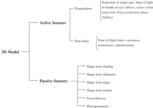
Nowadays the generation of a 3D model is mainly achieved using non-contact systems based on light waves, in particular using active or passive sensors (Fig. 1).
In some applications, other information derived from CAD models, measured surveys or GPS may also be used and integrated with the sensor data. Active sensors directly provide range data containing the 3D coordinates necessary for the network (mesh) generation phase. Passive sensors provide images that need further processing to derive the 3D object coordinates. After the measurements, the data must be structured and a consistent polygonal surface is then created to build a realistic representation of the modelled scene. A photo-realistic visualisation can afterwards be generated by texturing the virtual model with image information.
Considering active and passive sensors, four alternative methods for object and scene modelling can currently be distinguished:
(1) Image-based rendering (IBR). This does not include the generation of a geometric 3D model but, for particular objects and under specific camera motions and scene
con-Projection of single spot, sheet of light or bundle of rays (Moiré, colour-coded
projection, fringe projection, phase shifting)
Time of flight (lidar, continuous
modulation), interferometry
Shape from shading Time delay
Triangulation
Passive Sensors Active Sensors
3D Model
Shape from silhouette Shape from edges Shape from texture Focus/defocus Photogrammetry
Fig. 1. Three-dimensional acquisition systems for object measurement using non-contact methods based on light waves.
ditions, it might be considered a good technique for the generation of virtual views (Shum and Kang, 2000). IBR creates novel views of 3D environments directly from input images. The technique relies on either accurately knowing the camera positions or performing automatic stereomatching that, in the absence of geometric data, requires a large number of closely spaced images to succeed. Object occlusions and discontinuities, particularly in large-scale and geometrically complex environments, will affect the output. The ability to move freely into the scene and view objects from any position may be limited depending on the method used. Therefore, the IBR method is generally only used for applications requiring limited visualisation. (2) Image-based modelling (IBM). This is the widely used method for geometric surfaces
of architectural objects (Streilein, 1994; Debevec et al., 1996; van den Heuvel, 1999; Liebowitz et al., 1999; El-Hakim, 2002) or for precise terrain and city modelling (Gru¨n, 2000). In most cases, the most impressive and accurate results still remain those achieved with interactive approaches. IBM methods (including photogram-metry) use 2D image measurements (correspondences) to recover 3D object infor-mation through a mathematical model or they obtain 3D data using methods such as shape from shading (Horn and Brooks, 1989), shape from texture (Kender, 1981), shape from specularity (Healey and Binford, 1987), shape from contour (medical applications) (Asada, 1987; Ulupinar and Nevatia, 1995) and shape from 2D edge gradients (Winkelbach and Wahl, 2001). Passive image-based methods acquire 3D measurements from multiple views, although techniques to acquire three dimensions from single images (van den Heuvel, 1998; El-Hakim, 2001; Al Khalil and Grussen-meyer, 2002; Zhang et al., 2002; Remondino and Roditakis, 2003) are also neces-sary. IBM methods use projective geometry (Nister, 2004; Pollefeys et al., 2004) or a perspective camera model. They are very portable and the sensors are often low-cost.
(3) Range-based modelling. This method directly captures the 3D geometric information of an object. It is based on costly (at least for now) active sensors and can provide a highly detailed and accurate representation of most shapes. The sensors rely on artificial lights or pattern projection (Rioux et al., 1987; Besl, 1988). Over many years, structured light (Maas, 1992; Gaertner et al., 1996; Sablatnig and Menard, 1997), coded light (Wahl, 1984) or laser light (Sequeira et al., 1999) has been used for the measurement of objects. In the past 25 years many advances have been made in the field of solid-state electronics and photonics and many active 3D sensors have been developed (Blais, 2004). Nowadays many commercial solutions are available (including Breuckmann, Cyberware, Cyrax, Leica, Optech, ShapeGrabber, Riegl and Z + F), based on triangulation (with laser light or stripe projection), time-of-flight, continuous wave, interferometry or reflectivity measurement principles. They are becoming a very common tool for the scientific community but also for non-expert users such as cultural heritage professionals. These sensors are still expensive, designed for specific ranges or applications and they are affected by the reflective characteristics of the surface. They require some expertise based on knowledge of the capability of each different technology at the desired range, and the resulting data must be filtered and edited. Most of the systems focus only on the acquisition of the 3D geometry, providing only a monochrome intensity value for each range value. Some systems directly acquire colour information for each pixel (Blais, 2004) while others have a colour camera attached to the instrument, in a known configuration, so that the acquired texture is always registered with the geometry. However, this approach may not provide the best results since the ideal conditions for taking the
images may not coincide with those for scanning. Therefore, the generation of realistic 3D models is often supported by textures obtained from separate high-resolution colour digital cameras (Beraldin et al., 2002; Guidi et al., 2003). The accuracy at a given range varies significantly from one scanner to another. Also, due to object size, shape and occlusions, it is usually necessary to perform multiple scans from different locations to cover every part of the object: the alignment and integration of the different scans can affect the final accuracy of the 3D model. Furthermore, long-range sensors often have problems with edges, resulting in blunders or smoothing effects. On the other hand, for small and medium size objects (up to the size of a human or a statue) range-based methods can provide accurate and complete details with a high degree of automation (Beraldin et al., 1999).
(4) Combination of image- and range-based modelling. In many applications, a single modelling method that satisfies all the project requirements is still not available. Different investigations on sensor integration have been performed in El-Hakim and Beraldin (1994, 1995). Photogrammetry and laser scanning have been combined in particular for complex or large architectural objects, where no technique by itself can efficiently and quickly provide a complete and detailed model. Usually the basic shapes such as planar surfaces are determined by image-based methods while the fine details such as reliefs employ range sensors (Flack et al., 2001; Sequeira et al., 2001; Bernardini et al., 2002; Borg and Cannataci, 2002; El-Hakim et al., 2004; Beraldin et al., 2005).
Comparisons between range-based and image-based modelling are reported in Bo¨hler and Marbs (2004), Kadobayashi et al. (2004), Bo¨hler (2005) and Remondino et al. (2005). At the moment it can safely be said that, for all types of objects and sites, there is no single modelling technique able to satisfy all requirements of high geometric accuracy, portability, full automation, photo-realism and low cost as well as flexibility and efficiency.
In the next sections, only the terrestrial image-based 3D modelling problem for close range applications will be discussed in detail.
Terrestrial Image-Based 3D Modelling
Recovering a complete, detailed, accurate and realistic 3D model from images is still a difficult task, in particular for large and complex sites and if uncalibrated or widely separated images are used. Firstly, because the wrong recovery of the parameters could lead to inaccurate and deformed results. Secondly, because a wide baseline between the images always requires user interaction in the point measurements.
For many years photogrammetry dealt with the precise 3D reconstruction of objects from images. Although precise calibration and orientation procedures are required, suitable commercial packages are now available. They are all based on manual or semi-automated measurements (Australis, Canoma, ImageModeler, iWitness, PhotoGenesis, PhotoModeler, ShapeCapture). After the tie point measurement and bundle adjustment phases, they allow sensor calibration and orientation data and 3D object point coordinates, as well as wire-frame or textured 3D models, to be obtained from multi-image networks.
The overall image-based 3D modelling process consists of several well-known steps: design (sensor and network geometry); 3D measurements (point clouds, lines, etc.); structuring and modelling (segmentation, network/mesh generation, etc.); texturing and visualisation.
In the remainder of the paper, attention is focused on the details of 3D modelling from multiple images.
The research activities in terrestrial image-based modelling can be classified as follows: (1) Approaches that try to obtain a 3D model of the scene from uncalibrated images automatically (also called ‘‘shape from video’’ or ‘‘VHS to VRML’’ or ‘‘Video-To-3D’’). Many efforts have been made to completely automate the process of taking images, calibrating and orienting them, recovering the 3D coordinates of the imaged scene and modelling them, but while promising, the methods are thus far not always successful or proven in practical applications. The fully automated procedure, widely reported in the computer vision community (Fitzgibbon and Zisserman, 1998; Nister, 2004; Pollefeys et al., 2004), starts with a sequence of closely separated images taken with an uncalibrated camera. The system automatically extracts points of interest (such as corners), sequentially matches them across views and then computes camera parameters and 3D coordinates of the matched points using robust techniques. The key to the success of this fully automatic procedure is that successive images must not vary significantly, thus the images must be taken at short intervals. The first two images are generally used to initialise the sequence. This is done on a projective geometry basis and it is usually followed by a bundle adjustment. A ‘‘self-calibration’’ (or auto-calibration) to compute the intrinsic camera parameters (usually only the focal length) is generally used in order to obtain metric reconstruction (up to a scale) from the projective one. The 3D surface model is then automatically generated. In case of complex objects, further matching procedures are applied in order to obtain dense depth maps and a complete 3D model. See Scharstein and Szeliski (2002) for a recent overview of dense stereo-correspondence algorithms. Some approaches have also been presented for the automated extraction of image correspondences between wide baseline images (Pritchett and Zisserman, 1998; Matas et al., 2002; Ferrari et al., 2003; Xiao and Shah, 2003; Lowe, 2004), but their reliability and applicability for automated image-based modelling of complex objects is still not satisfactory as they yield mainly a sparse set of matched feature points. However, dense matching results under wide baseline conditions were reported in Strecha et al. (2003) and Megyesi and Chetverikov (2004). Automated image-based modelling methods rely on features that can be extracted from the scene and automatically matched, therefore occlusions, illumination changes, limited locations for the image acquisition and untextured surfaces are problematic. However, recent invariant point detector and descriptor operators, such as the SIFT operator (Lowe, 2004), proved to be more robust under large image variations. Another problem is that it is very common that an automated process ends up with areas containing too many features that are not all required for modelling while there are areas without any features or with a minimum number that cannot produce a complete 3D model. Automated processes require highly structured images with good texture, high frame rate and uniform camera motion, otherwise they will inevitably fail. Image configurations that lead to ambiguous projective recon-structions have been identified in Hartley (2000) and Kahl et al. (2001) while self-calibration-critical motions have been studied in Sturm (1997) and Kahl et al. (2000). The level of automation is also strictly related to the quality (precision) of the required 3D model. Automated reconstruction methods, even if able to recover the complete 3D geometry of an object, reported errors up to 5% (accuracy of c. 1:20) (Pollefeys et al., 2004), limiting their use to applications that require only ‘‘nice-looking’’ partial 3D models. Furthermore, post-processing operations are often required, which means that user interaction is still needed. Therefore, fully automated procedures are generally reliable and limited to finding point correspondences and camera poses
(Remondino, 2004; Roth, 2004; Forlani et al., 2005). ‘‘Nice-looking’’ 3D models can be used for visualisation purposes while for documentation, high accuracy and photo-realism, user interaction is mandatory. For all these reasons, more emphasis has been always put on semi-automated or interactive procedures, combining the human ability of image understanding with the powerful capacity and speed of computers. This has led to a number of promising approaches for the semi-automated modelling of architecture and other complex objects.
(2) Approaches that perform a semi-automated 3D reconstruction of the scene from oriented images. These approaches interactively or automatically orient and calibrate the images and afterwards perform the semi-automated modelling relying on the human operator (Streilein, 1994; Debevec et al., 1996; El-Hakim, 2002; Gibson et al., 2003; Guarnieri et al., 2004). Semi-automated approaches are much more common, in particular in case of complex geometric objects. The interactive work consists of the definition of the topology, followed by editing and post-processing of 3D data. The output model, based only on the measured points, usually consists of surface boundaries that are irregular, overlapping and need some assumptions in order to generate a correct surface model. The degree of automation of modelling increases when certain assumptions about the object, such as perpendicularity or parallel sur-faces, can be introduced. Debevec et al. (1996) developed a hybrid easy-to-use system to create 3D models of architectural features from a small number of photographs. It is the well-known Fac¸ade program, afterwards included to some extent in the com-mercial software Canoma. The basic geometric shape of a structure is first recovered using models of polyhedral elements. In this interactive step, the actual size of the elements and the camera pose are captured assuming that the intrinsic camera parameters are known. The second step is an automated matching procedure to add geometric details, constrained by the now-known basic model. The approach proved to be effective in creating geometrically accurate and realistic 3D models. The drawback is the high level of interaction. Since the assumed shapes determine the camera poses and all 3D points, the results are as accurate as the assumption that the structure elements match those shapes. Liebowitz et al. (1999) presented a method for creating 3D graphical models of scenes from a limited number of images, in particular in situations where no scene coordinate measurements are available (due to occlusions). After manual point measurements, the method employs constraints available from geometric relationships that are common in architectural scenes, such as parallelism and orthogonality, together with constraints available from the camera. Van den Heuvel (1999) uses a line-photogrammetric mathematical model and geo-metric constraints to recover the 3D shapes of polyhedral objects. Using lines, occluded object points can also be reconstructed and parts of occluded objects can be modelled by means of the introduction of coplanarity constraints. El-Hakim (2002) developed a semi-automatic technique (partially implemented in ShapeCapture) able to recover a 3D model of simple as well as complex objects. The images are calibrated and oriented without any assumption of the object shapes but using a photogram-metric bundle adjustment, with or without self-calibration, depending on the given configuration. This achieves higher geometric accuracy independent from the shape of the object. The modelling of complex object parts, such as groin vault ceilings or columns, is achieved by manually measuring in multiple images a number of seed points and fitting a quadratic or cylindrical surface. Using the recovered parameters of the fitted surface and the known internal and external camera parameters for a given image, any number of 3D points can be added automatically within the boundary of
the section. Lee and Nevatia (2003) developed a semi-automatic technique to model architecture where the camera is calibrated using the known shapes of the buildings being modelled. The models are created in a hierarchical manner by dividing the structure into basic shapes, fac¸ade textures and detailed geometry such as columns and windows. The detailed modelling of the geometry is an interactive procedure that requires the user to provide shape information such as width, height and radius and then the shape is completed automatically.
(3) Approaches that perform a fully automated 3D reconstruction of the scene from oriented images. The orientation and calibration are performed separately, interac-tively or automatically, while the 3D object reconstruction, based on object constraints, is fully automated. Most of the approaches explicitly make use of strong geometric constraints such as perpendicularity and verticality, which are likely to be found in architecture. Dick et al. (2001) employ the model-based recognition technique to extract high-level models in a single image and then use their projection onto other images for verification. The method requires parameterised building blocks with a priori distribution defined by the building style. The scene is modelled as a set of base planes corresponding to walls or roofs, each of which may contain offset 3D shapes that model common architectural elements such as windows and columns. Again, the full automation necessitates feature detection and a projective geometry approach; however, the technique also employs constraints, such as perpendicularity between planes, to improve the matching process. In Gru¨n et al. (2001), after a semi-automated image orientation step, a multi-photo geometrically constrained automated matching process is used to recover a dense point cloud of a complex object. The surface is measured fully automatically using multiple images and simultaneously deriving the 3D object coordinates. Werner and Zisserman (2002) proposed a fully automated Fac¸ade-like approach: instead of the basic shapes, the principal planes of the scene are created automatically to assemble a coarse model. A similar approach was presented in Schindler and Bauer (2003) and Wilczkowiak et al. (2003). The latter method searches three dominant directions that are assumed to be perpendicular to each other: the coarse model guides a more refined polyhedral model of details such as windows, doors and wedge blocks. Since this is a fully automated approach, it requires feature detection and closely spaced images for the automatic matching and camera pose estimation using projective geometry. D’Apuzzo (2003) developed an automated surface measurement procedure that, starting from a few seed points measured in multiple images, is able to match the homologous points within the Voronoi regions defined by the seed points.
In the next sections, the image-based modelling pipeline is analysed in detail.
Design and Recovery of the Network Geometry
The authors’ experience and different studies in close range photogrammetry (including Clarke et al., 1998; Fraser, 2001; Gru¨n and Beyer, 2001; El-Hakim et al., 2003) confirm that: (a) the accuracy of a network increases with the increase of the base to depth (B:D) ratio
and using convergent images rather than images with parallel optical axes;
(b) the accuracy improves significantly with the number of images in which a point appears. But measuring the point in more than four images gives less significant improvement;
(c) the accuracy increases with the number of measured points per image. However, the increase is not significant if the geometric configuration is strong and the measured points are well defined (like targets) and well distributed in the image;
(d) the image resolution (number of pixels) influences the accuracy of the computed object coordinates: on natural features, the accuracy improves significantly with image resolution, while the improvement is less significant on well-defined, large, resolved targets.
Factors concerning the camera calibration are:
(a) self-calibration (with or without known control points) is reliable only when the geometric configuration is favourable, mainly highly convergent images of a large number of (3D) targets spatially well distributed;
(b) a flat (2D) testfield could be employed for camera calibration if the images are acquired at many different distances, to allow the recovery of the correct focal length; (c) at least two or three images should be rotated by 90 degrees to allow the recovery of the principal point, that is, to break any projective coupling between the principal point offset and the camera station coordinates, and to provide a different variation of scale within the image;
(d) a complete camera calibration should be performed, in particular for the lens distor-tions. In most cases, particularly in modern digital cameras and for unedited images, the camera focal length can be found, albeit with less accuracy, in the header of the digital images. This can be used on uncalibrated cameras if self-calibration is not possible or unreliable.
In the light of all the above, in order to optimise the accuracy and reliability of 3D point measurement, particular attention must be given to the design of the network. Designing a network includes deciding on a suitable sensor and image measurement scheme; which camera to use; the imaging locations and orientations to achieve good imaging geometry; and many other considerations. The network configuration determines the quality of the calibration and defines the imaging geometry. Unfortunately, in many applications, the network design phase is not considered or is impossible to apply in the actual object setting, or the images are already available from archives, leading to less than ideal imaging geometry. Therefore, in practical cases, rather than simultaneously calibrate the internal camera parameters and reconstruct the object, it may be better first to calibrate the camera at a given setting using the most appropriate network design and afterwards recover the object geometry using the calibration parameters at the same camera setting. Advanced digital cameras can reliably save several settings.
The network geometry is optimally recovered by means of bundle adjustment (Brown, 1976; Triggs et al., 2000) (with or without self-calibration, depending on the given network configuration).
Surface Measurements
Once the images are oriented, the surface measurement step can be performed with manual or automated procedures. Automated photogrammetric matching algorithms developed for terrestrial images (Gru¨n et al., 2001, 2004; D’Apuzzo, 2003; Santel et al., 2003; Ohdake and Chikatsu, 2005) are usually area-based techniques that rely on the least squares matching algorithm (Gru¨n, 1985) which can be used on stereo or multiple images (Baltsavias, 1991). These methods can produce very dense point clouds but often do not take into consideration the geometrical conditions of the object surface and perhaps work with smoothing constraints
(Gru¨n et al., 2004; Remondino et al., 2005). Therefore, it is often quite difficult to correctly turn randomly generated point clouds into polygonal structures of high quality without losing important information and details. The smoothing effects of automated least-squares-based matching algorithms mainly result from the following:
(a) the image patches of the matching algorithm are assumed to correspond to planar object surface patches (for this reason the affine transformation is generally applied for the purpose of matching). Along small objects or corners, this assumption is no longer valid, therefore the features are smoothed out (Fig. 2);
(b) smaller image patches could theoretically avoid or reduce the smoothing effects, but may not be suitable for the correct determination of the matching reshaping para-meters because a small patch may not include enough image signal content. The use of high-resolution images (say 10 megapixels) in combination with advanced matching techniques (see, for example, Zhang, 2005) would enable the recovery of the fine details of an object and would also avoid smoothing effects.
After the image measurements, the matched 2D coordinates are transformed into 3D object coordinates using the previously recovered camera parameters (forward intersection). In the case of multi-photo geometrically constrained matching (Baltsavias, 1991), the 3D object coordinates are simultaneously derived together with the image points.
In the vision community, two-frame stereo-correspondence algorithms are predominantly used (Dhond and Aggarwal, 1989; Brown, 1992; Scharstein and Szeliski, 2002), producing a dense disparity map consisting of a parallax estimate at each pixel. Often the second image is resampled in accordance with the epipolar line, so as to have a parallax value in only one direction. A large number of algorithms have been developed and the dense output is generally used for view synthesis, image-based rendering or modelling of complete regions. Feature-based matching techniques differ from area-Feature-based methods by performing the matching on automatically extracted features or corners using operators such as the SIFT corner detector (Lowe, 2004) which produce points that are invariant under large geometric transformations. In theory, automated measurements should produce more accurate results compared to manual procedures: for example, on single points such as artificial targets, they can obtain an accuracy smaller than 1/25 of a pixel with least squares template matching. But within an automated procedure, mismatches, irrelevant points and missing parts (due to lack of texture) are usually present in the results, requiring a post-processing check and editing of the data.
Perspective centre
Image
Object
Fig. 2. Patch definition in least squares matching measurement (left). Triplet of images where patches are assumed to correspond to planar object surfaces and the assumption is not valid (right).
On the other hand, if the measurements are done in manual (mono- or stereoscopic) mode, there is a higher reliability of the measures but a smaller number of points that describe the object. Manual image measurements might recover all the object details but these can be time consuming and impractical. Moreover, to perform manual stereoscopic measurements correctly, it is very important for the operator to understand the functional behaviour of the specific 3D modelling software employed.
After the image measurements, surface modelling and 3D model visualisation can be performed, as described in the next sections.
From 3D Point Clouds to Surfaces
Polygons are usually the most flexible way to accurately represent the results of 3D measurements, providing an optimal surface description. For some modelling applica-tions, like building reconstruction, where the object is mainly described with planar or cylindrical patches, a small number of points are required and the structuring and surface generation is often achieved with few triangular patches or fitting particular surfaces to the data.
For other applications, such as statues, human body parts or complex objects, and in the case of denser point clouds, surface generation from the measured points is much more difficult and requires ‘‘smart algorithms’’ to triangulate all the measured points, in particular in the case of uneven and sparse point clouds.
The goal of surface reconstruction can be stated as follows: given a set of sample points Pi assumed to lie on or near an unknown surface S, create a surface model S¢
approximating S. A surface reconstruction procedure (also called surface triangulation) cannot exactly guarantee the recovery of S, since the information about it is obtained only through a finite set of sample points Pi. Sometimes additional information about the surface
(for example, breaklines) can be available and generally, as the sampling density increases, the output result S¢ is more likely to be topologically correct and converges to the original surface S. A good sample should be dense in detailed and curved areas and sparse in flat parts. But usually the measured points are unorganised and often noisy; moreover, the surface can be arbitrary, with an unknown topological type and with sharp features. Therefore, the reconstruction method must infer the correct geometry, topology and geometric features just from a finite set of sampled points. Usually if the input data does not satisfy certain properties required by the triangulation algorithm (good point distribution, high density, little noise, and so on), current commercial software tools will produce incorrect results.
The conversion of the measured 3D point cloud into a consistent polygonal surface is generally based on four steps:
(1) Pre-processing: in this phase erroneous data is eliminated and noise is smoothed out and points are added to fill gaps. The data may also be resampled to generate a model of efficient size (in case of dense depth maps from correspondence or range data). (2) Determination of the global topology of the object’s surface, deriving the
neigh-bourhood relations between adjacent parts of the surface. This operation typically needs some global sorting step and the consideration of possible constraints (such as breaklines), mainly to preserve special features such as edges.
(3) Generation of the polygonal surface: triangular (or tetrahedral) networks are created satisfying certain quality requirements, for example, a limit on the network element size or no intersection of breaklines.
(4) Post-processing: after surface generation, editing operations (edge corrections, tri-angle insertion, polygon editing, hole filling) are commonly applied to refine and correct the generated polygonal surface.
Commercial reverse engineering software packages such as Cyclone, Geomagic, PolyWorks and RapidForm perform all the previously described operations. Many other packages, in prototype form, are probably available in various research labs. A distinction should be made between 2½D surface interpolation packages and true 3D surface generation tools. Generally in close range 3D modelling, the objects are fully 3D, therefore, software for digital terrain or digital surface model (DTM/DSM) interpolation such as SCOP or Surfer is not always useful.
Surface Triangulation or Network (Mesh) Generation
Triangular network (mesh) generation is at the core of almost all surface reconstruction programs. See Edelsbrunner (2001) for a good introduction to the topic. A triangulation converts a given set of points into a consistent polygonal model; in English photogrammetric and geographical information terminology this is generally called a triangulated (or triangular) irregular network (TIN), while the computer graphics community tends to favour ‘‘mesh’’, the exact but somewhat misleading equivalent of the German Masche. This operation partitions the input data into ‘‘simplices’’ (its simplest elements) and usually generates vertices, edges and faces (representing the surface analysed) that meet only at shared edges. Finite element methods are used to subdivide the measured domain into many small elements, typically triangles or quadrilaterals in two dimensions and tetrahedra in three dimensions. An optimal triangulation is defined by measuring angles, edge lengths, height or area of the elements, while the error of the finite element approximations is usually related to the minimum angle of the elements. The vertices of the triangulation can be exactly the input points only, or may include extra points, called Steiner points, which are inserted to create a more optimal network (Bern and Eppstein, 1992). Triangulation can be performed in two dimensions or in three dimensions, in accordance with the geometry of the input data:
(1) 2D Triangulation: the input domain is a polygonal region of the plane and, as a result, triangles that intersect only at shared edges and vertices are generated. A well-known construction method is the Delaunay Triangulation (DT) that simultaneously opti-mises several quality measures such as the edge lengths or the areas of the elements. The Delaunay criterion ensures that no vertex lies within the interior of any of the circumcircles of the triangles in the (in general irregular) network. The DT of a given set of points is the dual of the Voronoi diagram (also called the Thiessen or Dirichlet tessellation). In the Voronoi diagram, each region consists of the part of the plane nearest to that node: connecting the nodes of the Voronoi cells that have common boundaries forms the Delaunay triangles.
(2) 2½D Triangulation: the input data is a set of points P in a plane, along with a real and unique elevation function f (x, y) at each point (x, y). A 2½D triangulation creates a linear function F interpolating P and defined on the region bounded by the convex hull of P. For each point p in P, F(p) is the weighted average of the elevation of the vertices of the triangle that contains p. Depending on the data structure (regular or almost randomly distributed), the generated surface may be described as an elevation grid or may remain in the form of a TIN model.
(3) Surfaces for 3D models: the input data is always a set of points P in R3, no longer restricted to a plane; therefore, the elevation function f (x, y) is no longer unique. This
kind of point cloud (an ‘‘unorganised point cloud’’) is the most complex input data for a correct mesh generation.
(4) 3D Triangulation: the triangulation in 3D is called tetrahedralisation or tetrahedrisa-tion. A tetrahedralisation is a partition of the input domain into a collection of tetra-hedra that meet only at shared faces (vertices, edges or triangles). Tetratetra-hedralisation results are much more complicated than a 2D triangulation. The types of input domains may include a simple polyhedron (sphere), a non-simple polyhedron (torus) or generic point clouds.
As there is a huge body of work on surface generation techniques, in the following part they are described in terms of four possible classifications.
A first and very general classification is done in accordance with the way the input data is disseminated:
(1) Unorganised point clouds: algorithms working on unorganised data (Owen, 1998) have no other information on the input data except their spatial position. They do not use any assumption on the object geometry or point adjacency or connectivity and therefore, before generating a polygonal surface, they usually structure the points according to their coherence. They need a good distribution of the input data and if the points are not uniformly distributed they easily fail.
(2) Structured point clouds: algorithms based on structured data (for example, Soucy and Laurendeau, 1992) can take into account additional information about the points (such as breaklines or coplanarity).
A further distinction can be drawn in accordance with the spatial subdivision of the points: (1) Surface-oriented algorithms do not distinguish between open and closed surfaces. Most of the available algorithms belong to this group (for example, Hoppe et al., 1992).
(2) Volume-oriented approaches work in particular with closed surfaces and are generally based on the Delaunay tetrahedralisation of the given set of sample points (Bois-sonnat, 1984; Curless and Levoy, 1996; Isselhard et al., 1998).
Another classification is based on the type of representation of the surface:
(1) Parametric representation: these methods represent the surface as a number of parametric surface patches, described by parametric equations. Multiple patches may then be pieced together to form a continuous surface. Examples of parametric rep-resentations include B-splines, Bezier curves and Coons patches (Terzopoulos, 1988). (2) Implicit representation: these methods try to find a smooth function that passes through all positions where the implicit function reduces to some specified value (usually zero) (Gotsman and Keren, 1998).
(3) Simplicial representation: in this representation the surface is a collection of simple entities including points, edges and triangles. This group includes Alpha shapes (Edelsbrunner and Mu¨cke, 1994) and the Crusts algorithm (Amenta et al., 1998). (4) Approximated surfaces: these do not always contain all the original points, but points
as near as possible to them. They can use a distance function (shortest distance of a point in space from the generated surface) to estimate the correct mesh (Hoppe et al., 1992). In this group can also be included warping-based surface reconstruction (deforming an initial surface so that it gives a good approximation of the given set of points) (Muraki, 1991) and implicit surface-fitting algorithms (for example, fitting piecewise polynomial functions to the given set of points) (Moore and Warren, 1991).
(5) Interpolated surfaces: these algorithms are used when precise models are requested. All the input data is used and correct connections between points are necessary (Dey and Giesen, 2001).
Finally, reconstruction methods can be divided according to their assumptions:
(1) Algorithms assuming fixed topological type: these usually assume that the topological type of the surface is known a priori (for example, plane, cylinder or sphere) (Brinkley, 1985; Hastie and Stu¨tzle, 1989).
(2) Algorithms exploiting structure or orientation information: many surface recon-struction algorithms exploit the structure of the data for their operation. For example, in case of multiple scans, they can use the adjacency relationship of the data within each range image (Merriam, 1992). Other reconstruction methods instead use knowledge of the orientation of the surface that is supplied with the data. For example, if the points are obtained from volumetric data, the gradient of this data can provide orientation information useful for the reconstruction (Miller et al., 1991).
Texturing and Visualisation
In many applications with large volumes of points, such as particle tracking, or fog, cloud or water visualisation, the data can be visualised simply by drawing all the samples. However, for some objects, particularly those with sparse point clouds, this technique does not give an accurate representation and does not provide realistic visualisation. Moreover, the visualisation of a 3D model is often the only product of interest for the external world and remains the only possible contact with the model. Therefore, a realistic and accurate visualisation is often required.
Generally, after the creation of a polygonal mesh, the results are visualised in wire-frame form, or in shaded and/or textured mode. In the case of a DTM, other common methods of representation are contour maps, colour-shaded models (hypsometric shading) or slope maps. In the photogrammetric community, many attempts at the visualisation of 3D models had been made by the beginning of the 1990s. Small objects such as cars and human faces, as well as architectural objects, were displayed as wire-frame models or static orthophotos. With the advances in the speed, memory size and graphics capabilities of computers, full geometric 3D models with textures are now typical for photo-realistic representation. A detailed review of tools and techniques for the visualisation of photogrammetric data is presented in Patias (2001).
In texture mapping, colour images are mapped onto a 3D geometric surface. Knowing the parameters of the interior and exterior orientation of the images, the corresponding image coordinates are calculated for each vertex of a triangle on the 3D surface. Then colour RGB values within the projected triangle are attached to the surface. Although this seems straightforward, there are many factors affecting the photo-realism of a textured 3D model:
(1) Radiometric image distortion: this effect comes from the use of different images acquired from different positions or with different cameras or under different lighting conditions. Therefore, in the 3D textured model, discontinuities and artefacts are present along the edges of adjacent triangles textured using different images. To avoid this, several techniques, such as blending methods based on weighted functions, can be used (Niem and Broszio, 1995; Debevec et al., 1996; Havaldar et al., 1996; Pulli et al., 1998; Visnovcova et al., 2001; Rocchini et al., 2002; Beauchesne and Roy, 2003; Kim and Pollefeys, 2004; Remondino and Niederoest, 2004).
(2) Geometric scene distortion: this kind of error is generated from an incorrect camera calibration and orientation, an imprecise image registration or errors in the mesh generation. Any of these sources of error may prevent the preservation of detailed content such as straight edges or major discontinuities in the surface. Accurate photo-grammetric bundle adjustment, precise image registration and polygon refinement must be employed to reduce or minimise these geometric errors. Weinhaus and Devich (1999) gave a detailed account of the geometric corrections that must be applied to remove distortions resulting from the transformation of the texture from the image plane to the triangle plane.
(3) Dynamic range of the image: digital images often have a low dynamic range. Therefore, bright areas are generally saturated while dark parts contain low signal to noise (S/N) ratio. To overcome these problems high dynamic range images should be created (Debevec and Malik, 1997).
(4) Object occlusions: extraneous static or moving objects such as pedestrians, cars, other monuments or trees, imaged in front of the objects to be modelled are obviously undesirable and should be as far as possible removed in the pre-processing step (Bo¨hm, 2004; Ortin and Remondino, 2005).
During the visualisation, a common problem is the presence of aliasing effects, in particular during animations and when vector layers are overlapped onto the 3D geometry. This is because, particularly when the surface is far away, a pixel displayed on that surface may be associated with several texture elements (texels) from the texture map, resulting in aliasing and jagged lines. Some commercial packages have no anti-aliasing control for geometry and texture while more powerful animation software, such as 3DMax and Maya, has a fully controlled anti-aliasing capability for the rendering process.
Recently, due to large geometric data-sets and high-resolution texture images in the 3D models, new methods for real-time visualisation, animation and transmission of the data have been developed. The main requirement is that the rendering algorithm should be capable of delivering images at real-time frame rates (at least 20 frames per second), even for very large numbers of polygons, and with high-resolution textures without losing important information. See Heckbert (1997) and Luebke (2001) for surveys of basic methods. Usually two types of information are encoded in the networks or meshes generated: (1) the geometrical information (the positions of the vertices in the space and the surface normals) and (2) the topological information (that is, the network/mesh connectivity and the relations between the faces). Considering these two types of information and the needs listed earlier, many algorithms have been proposed for interactive visualisation of triangular networks, based on:
(1) Compression of the geometry of the data: these algorithms try to improve the storage of the numerical information about the points of the networks (positions of the ver-tices, normals, colours, etc.) or they look for an efficient encoding of the network topology (Deering, 1995; De Floriani et al., 1998; Taubin and Rossignac, 1998). (2) Control of the level of detail (LOD): this is done to keep in memory only what is
visible at a certain instant. The LOD varies smoothly throughout the scene and the rendering depends on the current position of the model (hierarchical LOD). A control on the LOD allows view-dependent refinement of the meshes so that details that are not visible (occluded primitives or back faces) are not shown (Kumar et al., 1996; Duchaineau et al., 1997; Hoppe, 1998). Heok and Daman (2004) review automatic model simplification and run-time LOD techniques, LOD simplification models and error evaluation. The LOD control can also be performed on the texture using image pyramids (also called MIP-mapping, from the Latin multum in parvo) or ‘‘impostors’’
(Karner et al., 2001; Wimmer et al., 2001). An effective performance enhancement method for both geometry and texture is called ‘‘occlusion culling’’, which skips objects that are occluded by other objects or surfaces (see, for example, Zhang, 1998). One inconvenient aspect of LOD techniques is the ‘‘popping’’ effect that occurs during the changes of resolution levels. ‘‘Geomorphing’’ techniques (a smooth visual transition between two geometric meshes) have been introduced to reduce or hide transitional artefacts and improve the visual quality while rendering with view-dependent approaches (Hoppe, 1997, 1998; Lindstrom and Pascucci, 2002; Borgeat et al., 2005).
(3) Mesh optimisation, filtering and decimation: these approaches simplify the meshes that exceed the size of main memory by simply removing vertices, edges and tri-angles. The methods can iteratively remove vertices that do not pass a certain dis-tance/angle criterion, or collapse edges into a unique vertex (Hoppe, 1997). Other approaches are based on vertex clustering (Rossignac and Borrel, 1993), Wiener filtering (Alexa, 2002) and wavelets (Gross et al., 1996).
(4) Point-based rendering: with this method, a smaller number of primitives is displayed. The method allows for simple and efficient view-dependent computations and com-pact representation of the model for a high rendering rate (Rusinkiewicz and Levoy, 2000; Dachsbacher et al., 2003). The approach generally produces more artefacts than triangle-based visualisation methods, but recently Zwicker et al. (2004) showed that high quality rendering can be obtained at the cost of complex filtering techniques. (5) Exploiting of capabilities of GPUs: these methods take advantage of the recent and
rapid expansion of graphics processing units (GPUs) to reduce the load on the CPU (Levenberg, 2002; Cignoni et al., 2004; Borgeat et al., 2005).
(6) Out-of-core management: these approaches try to handle data that exceeds the size of the main memory (Cignoni et al., 2003; Isenburg et al., 2003).
Another big difficulty at the moment is the translation and interchange of 3D data between modelling and visualisation packages as well as between users. Generally, every commercial software package has its own (binary) format. Even if they allow the export of files in other formats, the resulting 3D file may be incorrectly visualised in other packages. Some commercial converters of 3D graphics file formats are available, but standardisation of the many 3D formats is desirable to facilitate the exchange of models.
Summary and Conclusions
Different approaches to the acquisition, processing and visualisation of 3D information from images have been examined, mainly for close range applications. Compared to laser scanners, the main advantages of image-based modelling are that the sensors are generally inexpensive and portable and that 3D information can be accurately recovered regardless of the size of the object. Although image-based modelling can produce accurate and realistic-looking models, even in some cases comparable to models resulting from laser scanning, it remains highly interactive since most of the current automated methods are still unproven in real applications. Automated IBM also cannot capture detail on unmarked or featureless surfaces without assumptions about surface shape.
The creation of geometrically correct, detailed and complete 3D models of complex objects therefore remains a difficult problem and still a popular topic for investigation. If the goal is the creation of accurate, complete and photo-realistic 3D models of medium- and large-scale objects under practical situations, then full automation is still beyond reach. In reality,
proper performance evaluation of automated techniques is generally not possible, which makes it difficult to select them for actual applications. This may ultimately change due to the efforts currently being invested in those techniques, but until then semi-automated techniques are strongly recommended.
In semi-automated approaches, parts of the process that can readily be performed by humans, such as extracting seed points and topological surface segmentation, remain interactive, while those best performed by the computer, such as feature extraction, point correspondence, image registration and modelling of segmented regions should be automated. Many of the problems of converting a measured point cloud into a realistic 3D polygonal model that can satisfy high modelling and visualisation demands have not been completely solved. Furthermore, all the existing packages for modelling and visualising 3D objects are specific for certain types of data. Commercial ‘‘reverse engineering’’ packages do not produce correct meshes without dense point clouds. Therefore, much more time is often spent in mesh generation and editing than in point measurement. Issues affecting photo-realism or visual quality, such as geometric and radiometric distortions, and those affecting interactive visualisation or rendering at high frame rates, are still active research areas in computer graphics. Due to the large size of most detailed models, it is not usually feasible to achieve both photo-realism and smooth navigation with current computer and graphics hardware, without simplification and/or creative rendering techniques such as controlling the LOD. The hardware is of course always improving, but model sizes are increasing at a higher rate, to satisfy the ever-growing need for realistic detail.
references
Alexa, M., 2002. Wiener filtering of meshes. IEEE Computer Society Proceedings of Shape Modelling Inter-national (SMI’02), Washington, DC, 17th to 22nd May 2002. 279 pages: 51–57.
Al Khalil, O. and Grussenmeyer, P., 2002. Single image and topology approaches for modelling buildings. International Archives of the Photogrammetry, Remote Sensing and Spatial Information Sciences, 34(5): 131– 136.
Amenta, N., Bern, M. and Kamvysselis, M., 1998. A new Voronoi-based surface reconstruction algorithm. ACM Proceedings of SIGGRAPH ’98, Orlando, Florida. 460 pages: 415–421.
Asada, M., 1987. Cylindrical shape from contour and shading without knowledge of lighting conditions or surface albedo. Proceedings of the 1st IEEE International Conference on Computer Vision, London, UK, 8th to 11th June 1987. 707 pages: 412–416.
Baltsavias, E. P., 1991. Multiphoto geometrically constrained matching. Ph.D. thesis, Institute of Geodesy and Photogrammetry, ETH Zurich, Switzerland. 221 pages.
Beauchesne, E, and Roy, S., 2003. Automatic relighting of overlapping textures of a 3D model. Proceedings of IEEE Computer Vision and Pattern Recognition, 18th to 20th June 2003. Vol. 2, 742 pages: 166–173. Beraldin, J. A., Blais, F., Cournoyer, L., Rioux, M., El-Hakim, S. F., Rodella, R., Bernier, F. and
Harrison, N., 1999. Digital 3D imaging system for rapid response on remote sites. IEEE Proceedings of Second 3-D Digital Imaging and Modeling Conference, Ottawa, Canada, 4th to 8th October 1999. 546 pages: 34–43.
Beraldin, J.-A., Picard, M., El-Hakim, S. F., Godin, G., Latouche, C., Valzano, V. and Bandiera, A., 2002. Exploring a Byzantine crypt through a high-resolution texture mapped 3D model: combining range data and photogrammetry. Proceedings of the CIPA WG6 International Workshop on Scanning for Cultural Heritage Recording, Corfu, Greece, 1st to 2nd September 2002. 159 pages: 65–72.
Beraldin, J.-A., Picard, M., El-Hakim, S. F., Godin, G., Valzano, V. and Bandiera, A., 2005. Combining 3D technologies for cultural heritage interpretation and entertainment. Proceedings of SPIE-IS&T Electronic Imaging: Videometrics VIII, San Jose, California, 18th to 20th January 2005. Vol. 5665, 374 pages: 108–118. Bern, M. W. and Eppstein, D., 1992. Mesh generation and optimal triangulation. Chapter 1 in Computing in Euclidean Geometry (Eds. D.-Z. Du and F. K. Hwang). World Scientific, River Edge, New Jersey. Lecture Notes Series on Computing, Vol. 1, 385 pages: 23–90.
Bernardini, F., Rushmeier, H., Martin, I. M., Mittleman, J. and Taubin, G., 2002. Building a digital model of Michelangelo’s Florentine Pieta. IEEE Computer Graphics and Applications, 22(1): 59–67.
Besl, P. J., 1988. Active, optical range imaging sensors. Machine Vision and Applications, 1(2): 127–152. Blais, F., 2004. Review of 20 years of range sensor development. Journal of Electronic Imaging, 13(1): 231–243. Bo¨ hler, W., 2005. Comparison of 3D laser scanning and other 3D measurement techniques. Recording, Modelling and Visualisation of Cultural Heritage (Eds. E. P. Baltsavias, A. Gru¨n, L. Van Gool and M. Pateraki). Taylor & Francis, London, UK. 513 pages: 89–99.
Bo¨ hler, W. and Marbs, A., 2004. 3D scanning and photogrammetry for heritage recording: a comparison. Proceedings of the 12th International Conference on Geoinformatics, Ga¨vle, Sweden, 7th to 9th June 2004. 291–298.
Bo¨ hm, J., 2004. Multi-image fusion for occlusion-free fac¸ade texturing. International Archives of the Photo-grammetry, Remote Sensing and Spatial Information Sciences, 35(5): 867–872.
Boissonnat, J.-D., 1984. Geometric structures for three-dimensional shape representation. ACM Transactions on Graphics, 3(4): 266–286.
Borg, C. E. and Cannataci, J. A., 2002. Thealasermetry: a hybrid approach to documentation of sites and artefacts. Proceedings of the CIPA WG6 International Workshop on Scanning for Cultural Heritage Recording, Corfu, Greece, 1st to 2nd September 2002. 159 pages: 93–104.
Borgeat, L., Godin, G., Blais, F., Massicotte, P. and Lahanier, C., 2005. GoLD: interactive display of huge coloured and textured models. ACM Transactions on Graphics, 24(3): 869–877.
Brinkley, J. F., 1985. Knowledge-driven ultrasonic three-dimensional organ modeling. IEEE Transactions on Pattern Analysis and Machine Intelligence, 7(4): 431–441.
Brown, D. C., 1976. The bundle adjustment—progress and prospects. International Archives of Photogrammetry, 21(3): 1–33.
Brown, L. G., 1992. A survey of image registration techniques. ACM Computing Surveys, 24(4): 325–376. Cignoni, P., Montani, C., Rocchini, C. and Scopigno, R., 2003. External memory management and
simpli-fication of huge meshes. IEEE Transactions on Visualization and Computer Graphics, 9(4): 525–537. Cignoni, P., Ganovelli, F., Gobbetti, E., Marton, F., Ponchio, F. and Scopigno, R., 2004. Adaptive
tetrapuzzles: efficient out-of-core construction and visualization of gigantic multiresolution polygonal models. ACM Transactions on Graphics, 23(3): 796–803.
Clarke, T. A., Wang, X. and Fryer, J. G., 1998. The principal point and CCD cameras. The Photogrammetric Record, 16(92): 293–312.
Curless, B. and Levoy, M., 1996. A volumetric method for building complex models from range images. ACM Proceedings of SIGGRAPH ’96, New Orleans, Louisiana, 4th to 9th August 1996. 518 pages: 303–312. Dachsbacher, C., Vogelgsang, C. and Stamminger, M., 2003. Sequential point trees. ACM Transactions on
Graphics, 22(3): 657–662.
D’Apuzzo, N., 2003. Surface measurement and tracking of human body parts from multi station video sequences. Ph.D. thesis, No. 15271, Institute of Geodesy and Photogrammetry, ETH Zurich, Switzerland, 147 pages. Debevec, P. E., Taylor, C. J. and Malik, J., 1996. Modeling and rendering architecture from photographs:
a hybrid geometry- and image-based approach. ACM Proceedings of SIGGRAPH ’96, New Orleans, Louisiana, 4th to 9th August 1996. 518 pages: 11–20.
Debevec, P. E. and Malik, J., 1997. Recovering high dynamic range radiance maps from photographs. ACM Proceedings of SIGGRAPH ’97, Los Angeles, California, 3rd to 8th August 1997. 494 pages: 369–378. Deering, M., 1995. Geometry compression. ACM Proceedings of SIGGRAPH ’95, Los Angeles, California, 6th to
11th August 1995. 509 pages: 13–20.
De Floriani, L., Magillo, P. and Puppo, E., 1998. Efficient implementation of multi-triangulations. Proceed-ings of IEEE Visualization ’98, Research Triangle Park, North Carolina, 18th to 23rd October 1998. 509 pages: 43–50.
Dey, T. K. and Giesen, J., 2001. Detecting undersampling in surface reconstruction. Proceedings of the 17th ACM Symposium on Computational Geometry, Medford, 3rd to 5th June 2001. 328 pages: 257–263.
Dhond, U. and Aggarwal, J. K., 1989. Structure from stereo—a review. IEEE Transactions on System, Man, and Cybernetics, 19(6): 1489–1510.
Dick, A. R., Torr, P. H. S., Ruffle, S. J. and Cipolla, R., 2001. Combining single view recognition and multiple view stereo for architectural scenes. Proceedings of the Eighth IEEE International Conference on Computer Vision, Vancouver, Canada, 9th to 12th July 2001. Vol. 1, 770 pages: 268–274.
Duchaineau, M., Wolinsky, M., Sigeti, D. E., Miller, M. C., Aldrich, C. and Mineev-Weinstein, M. B., 1997. ROAMing terrain: real-time optimally adapting meshes. Proceedings of IEEE Visualization ’97, Phoenix, Arizona, 19th to 24th October 1997. 519 pages: 81–88.
Edelsbrunner, H., 2001. Geometry and Topology for Mesh Generation. Cambridge University Press, Cambridge. Cambridge Monographs on Applied and Computational Mathematics, No. 7, 190 pages.
Edelsbrunner, H. and Mu¨cke, E. P., 1994. Three-dimensional alpha shapes. ACM Transactions on Graphics, 13(1): 43–72.
El-Hakim, S. F., 2001. A flexible approach to 3D reconstruction from single images. ACM Proceedings of SIGGRAPH ’01, Technical Sketches, Los Angeles, California, 12th to 17th August 2001. 280 pages: 186. El-Hakim, S. F., 2002. Semi-automatic 3D reconstruction of occluded and unmarked surfaces from widely separated views. International Archives of the Photogrammetry, Remote Sensing and Spatial Information Sciences, 34(5): 143–148.
El-Hakim, S. F. and Beraldin, J. A., 1994. On the integration of range and intensity data to improve vision-based three-dimensional measurements. Proceedings of SPIE Videometrics III, Boston, Massachusetts, 2nd to 4th November 1994. Vol. 2350, 364 pages: 306–321.
El-Hakim, S. F. and Beraldin, J. A., 1995. Configuration design for sensor integration. Proceedings of SPIE Videometrics IV, Philadelphia, Pennsylvania, 22nd to 26th October 1995. Vol. 2598, 390 pages: 274–285. El-Hakim, S. F., Beraldin, J.-A. and Blais, F., 2003. Critical factors and configurations for practical 3D image-based modeling. VI Conference on Optical 3D Measurement Techniques, Zurich, Switzerland (Eds. A. Gru¨n and H. Kahmen). Vol. 2, 342 pages: 159–167.
El-Hakim, S. F., Beraldin, J.-A., Picard, M. and Godin, G., 2004. Detailed 3D reconstruction of large-scale heritage sites with integrated techniques. IEEE Computer Graphics and Applications, 24(3): 21–29. Ferrari, V., Tuytelaars, T. and Van Gool, L., 2003. Wide-baseline multiple-view correspondences.
Pro-ceedings of IEEE Computer Vision and Pattern Recognition, Madison, Wisconsin, 16th to 22nd June 2003. Vol. 1, 872 pages: 718–725.
Fitzgibbon, A. and Zisserman, A., 1998. Automatic 3D model acquisition and generation of new images from video sequences. Proceedings of the European Signal Processing Conference, Rhodes, Greece, 8th to 11th September 1998. 2564 pages: 1261–1269.
Flack, P. A., Willmott, J., Browne, S. P., Arnold, D. B. and Day, A. M., 2001. Scene assembly for large scale urban reconstructions. Proceedings of the 3rd International Symposium on Virtual Reality, Archaeology and Cultural Heritage (VAST 2001), Glyfada, Greece, 28th to 30th November 2001. 354 pages: 227–234. Forlani, G., Roncella, R. and Remondino, F., 2005. Structure and motion reconstruction of short mobile
mapping image sequences. VII Conference on Optical 3D Measurement Techniques, Vienna, Austria (Eds. A. Gru¨n and H. Kahmen). Vol. 2, 425 pages: 265–274.
Fraser, C. S., 2001. Network design. Chapter 9 in Close Range Photogrammetry and Machine Vision (Ed. K. B. Atkinson). Whittles, Caithness, Scotland. 371 pages: 256–281.
Gaertner, H., Lehle, P. and Tiziani, H. J., 1996. New highly efficient binary codes for structured light methods. Proceedings of SPIE Three-Dimensional and Unconventional Imaging for Industrial Inspection and Metro-logy. Vol. 2599: 4–13.
Gibson, S., Hubbold, R. J., Cook, J. and Howard, T. L. J., 2003. Interactive reconstruction of virtual en-vironments from video sequences. Computers & Graphics, 27(2): 293–301.
Gotsman, C. and Keren, D., 1998. Tight fitting of convex polyhedral shapes. International Journal of Shape Modelling, 4(3/4): 111–126.
Gross, W. I., Staadt, O. G. and Gatti, R., 1996. Efficient triangular surface approximations using wavelets and quadtree structures. IEEE Transactions on Visualization and Computer Graphics, 2(2): 130–143.
Gru¨ n, A., 1985. Adaptive least square correlation: a powerful image matching technique. South African Journal of Photogrammetry, Remote Sensing and Cartography, 14(3): 175–187.
Gru¨ n, A., 2000. Semi-automated approaches to site recording and modelling. International Archives of Photo-grammetry and Remote Sensing, 33(5/1): 309–318.
Gru¨ n, A. and Beyer, H. A., 2001. System calibration through self-calibration. In Calibration and Orientation of Cameras in Computer Vision (Eds. A. Gru¨n and T. S. Huang). Springer, Berlin. Vol. 34, 235 pages: 163–193. Gru¨ n, A., Zhang, L. and Visnovcova, J., 2001. Automatic reconstruction and visualization of a complex Buddha tower of Bayon, Angkor, Cambodia. Proceedings of 21st Wissenschaftlich-Technische Jahrestagung der Deutschen Gesellschaft fu¨r Photogrammetrie und Fernerkundung (DGPF). 588 pages: 289–301. Gru¨ n, A., Remondino, F. and Zhang, L., 2004. Photogrammetric reconstruction of the Great Buddha of
Bamiyan, Afghanistan. The Photogrammetric Record, 19(107): 177–199.
Guarnieri, A., Vettore, A. and Remondino, F., 2004. Photogrammetry and ground-based laser scanning: assessment of metric accuracy of the 3D model of Pozzoveggiani church. FIG Working Week 2004, The Olympic Spirit in Surveying, Athens, Greece, 22nd to 27th May 2004 (on CD-ROM).
Guidi, G., Beraldin, J.-A., Ciofi, S. and Atzeni, C., 2003. Fusion of range camera and photogrammetry : a systematic procedure for improving 3-D models metric accuracy. IEEE Transactions on Systems, Man, and Cybernetics, 33(4): 667–676.
Hartley, R. I., 2000. Ambiguous configurations for 3-view projective reconstruction. Proceedings of 6th European Conference on Computer Vision, Part 1, Dublin, Ireland, 26th June to 1st July 2000. Springer, Berlin/Heidelberg. Lecture Notes in Computer Science, Vol. 1842, 949 pages: 922–935.
Hastie, T. and Stu¨tzle, W., 1989. Principal curves. Journal of the American Statistical Association, 84(406): 502–516.
Havaldar, P., Lee, M.-S. and Medioni, G., 1996. View synthesis from unregistered 2-D images. Proceedings of Graphics Interface ’96, Toronto, Ontario, Canada, 22nd to 24th May 1996. 258 pages: 61–69. Healey, G. and Binford, T. O., 1987. Local shape from specularity. Proceedings of the 1st IEEE International
Conference on Computer Vision, London, UK, 8th to 11th June 1987. 707 pages: 151–160.
Heckbert, P. S., 1997. Multiresolution surface modelling. Course Notes 25. ACM Proceedings of SIGGRAPH ’97, Los Angeles, California, 3rd to 8th August 1997. 336 pages.
Heok, T. K. and Daman, D., 2004. A review on level of detail. Proceedings of the IEEE International Conference on Computer Graphics, Imaging and Visualization, Penang, Malaysia, 26th to 29th June 2004. 276 pages: 70–75.
Heuvel, F. A. van den, 1998. 3D reconstruction from a single image using geometric constraint. ISPRS Journal of Photogrammetry and Remote Sensing, 53(6): 354–368.
Heuvel, F. A. van den, 1999. Line-photogrammetric mathematical model for the reconstruction of polyhedral objects. Proceedings of SPIE Videometrics VI. Vol. 3641, 300 pages: 60–71.
Hoppe, H., 1997. View-dependent refinement of progressive meshes. ACM Proceedings of SIGGRAPH ’97, Los Angeles, California, 3rd to 8th August 1997. 494 pages: 189–198.
Hoppe, H., 1998. Smooth view-dependent level-of-detail control and its application to terrain rendering. Pro-ceedings of IEEE Visualization ’98, Research Triangle Park, North Carolina, 18th to 23rd October 1998. 509 pages: 35–42.
Hoppe, H., DeRose, T., Duchamp, T., McDonald, J. and Stu¨tzle, W., 1992. Surface reconstruction from unorganized points. Computer Graphics, 26(2): 71–78.
Horn, B. K. P. and Brooks, M. J. (Eds.), 1989. Shape from Shading. MIT Press, Cambridge, Massachusetts. 577 pages.
Ikeuchi, K. and Sato, Y. (Eds.), 2001. Modeling from Reality. Kluwer Academic, Norwell, Massachusetts. 232 pages.
Isenburg, M., Lindstrom, P., Gumhold, S. and Snoeyink, J., 2003. Large mesh simplification using pro-cessing sequences. Proceedings of 14th IEEE Visualization ’03, Seattle, Washington, 19th to 24th October 2003. 642 pages: 465–472.
Isselhard, F., Brunnett, G. and Schreiber, T., 1998. Polyhedral approximation and first order segmentation of unstructured point sets. Proceedings of Computer Graphics International (CGI’98), Hanover, Germany, 22nd to 26th June 1998. 800 pages: 433–443.
Kadobayashi, R., Kochi, N., Otani, H. and Furukawa, R., 2004. Comparison and evaluation of laser scanning and photogrammetry and their combined use for digital recording of cultural heritage. International Archives of the Photogrammetry, Remote Sensing and Spatial Information Sciences, 35(5): 401–406. Kahl, F., Triggs, B. and A˚ stro¨m, K., 2000. Critical motions for auto-calibration when some intrinsic parameters
can vary. Journal of Mathematical Imaging and Vision, 13(2): 131–146.
Kahl, F., Hartley, R. and A˚ stro¨m, K., 2001. Critical configurations for n-view projective reconstruction. IEEE Proceedings of Computer Vision and Pattern Recognition, Kauai, Hawaii, 8th to 14th December 2001. Vol. 2, 806 pages: 158–163.
Karner, K., Bauer, J., Klaus, A., Leberl, F. and Grabner, M., 2001. Virtual habitat: models of the urban outdoors. Automatic Extraction of Man-Made Objects from Aerial and Space Images (III) (Eds. E. P. Baltsavias, A. Gru¨n and L. Van Gool). Balkema, Lisse, the Netherlands. 415 pages: 393–402.
Kender, J. R., 1981. Shape from Texture. Carnegie Mellon University, AAT 8114629. 222 pages.
Kim, S. J. and Pollefeys, M., 2004. Radiometric alignment of image sequences. Proceedings of IEEE Computer Vision and Pattern Recognition, Washington, DC, 27th June to 2 July 2004. Vol. 1, 901 pages: 645–651. Kumar, S., Manocha, D., Garrett, W. and Lin, M. E., 1996. Hierarchical back-face computation.
Pro-ceedings Eurographics Rendering Workshop, Porto, Portugal, 27th to 31st August 1996. 278 pages: 235–244. Lee, S. C. and Nevatia, R., 2003. Interactive 3D building modelling using a hierarchical representation. Pro-ceedings of IEEE Workshop on Higher-Level Knowledge in 3D Modelling and Motion in conjunction with 9th International Conference on Computer Vision, Nice, France, 17th October 2003. 83 pages: 58–65. Levenberg, J., 2002. Fast view-dependent level-of-detail rendering using cached geometry. Proceedings of IEEE
Visualization ’02, Boston, Massachusetts, 27th October to 1st November 2002. 584 pages: 259–265. Liebowitz, D., Criminisi, A. and Zisserman, A., 1999. Creating architectural models from images. Computer
Graphics Forum, 18(3): 39–50.
Lindstrom, P. and Pascucci, V., 2002. Terrain simplification simplified: a general framework for view-dependent out-of-core visualization. IEEE Transactions on Visualization and Computer Graphics, 8(3): 239–254. Lowe, D. G., 2004. Distinctive image features from scale-invariant keypoints. International Journal of Computer