READ THESE TERMS AND CONDITIONS CAREFULLY BEFORE USING THIS WEBSITE.
https://nrc-publications.canada.ca/eng/copyright
Vous avez des questions? Nous pouvons vous aider. Pour communiquer directement avec un auteur, consultez la première page de la revue dans laquelle son article a été publié afin de trouver ses coordonnées. Si vous n’arrivez pas à les repérer, communiquez avec nous à PublicationsArchive-ArchivesPublications@nrc-cnrc.gc.ca.
Questions? Contact the NRC Publications Archive team at
PublicationsArchive-ArchivesPublications@nrc-cnrc.gc.ca. If you wish to email the authors directly, please see the first page of the publication for their contact information.
NRC Publications Archive
Archives des publications du CNRC
This publication could be one of several versions: author’s original, accepted manuscript or the publisher’s version. / La version de cette publication peut être l’une des suivantes : la version prépublication de l’auteur, la version acceptée du manuscrit ou la version de l’éditeur.
Access and use of this website and the material on it are subject to the Terms and Conditions set forth at
Behaviour of load-bearing wood-stud shear walls exposed to fire
Kodur, V. K. R.; Bénichou, N.; Sultan, M. A.
https://publications-cnrc.canada.ca/fra/droits
L’accès à ce site Web et l’utilisation de son contenu sont assujettis aux conditions présentées dans le site LISEZ CES CONDITIONS ATTENTIVEMENT AVANT D’UTILISER CE SITE WEB.
NRC Publications Record / Notice d'Archives des publications de CNRC:
https://nrc-publications.canada.ca/eng/view/object/?id=ac5f4fb7-3cf7-41cf-b93c-8a3e51fb0476 https://publications-cnrc.canada.ca/fra/voir/objet/?id=ac5f4fb7-3cf7-41cf-b93c-8a3e51fb0476
Behaviour of load-bearing wood-stud shear walls
exposed to fire
Kodur, V.R.; Benichou, N.; Sultan, M.A.
A version of this paper is published in / Une version de ce document se trouve dans :
Interflam 2001, 9th International Fire Science & Engineering Conference, Edinburgh, Scotland, v. 2, pp. 1369-1374
www.nrc.ca/irc/ircpubs
NRCC-44519
BEHAVIOUR OF LOAD-BEARING WOOD-STUD
SHEAR WALLS EXPOSED TO FIRE
V. K. R. Kodur, N. Benichou and M. A. Sultan Institute for Research in Construction
National Research Council Canada Ottawa, Ontario, Canada, K1A 0R6
ABSTRACT
This paper presents the results from an experimental study on the behaviour of load-bearing gypsum board protected, wood-stud shear wall assemblies. The experimental studies consisted of fire resistance tests on 12 full-scale wall assemblies. The factors investigated included effects of placement of shear membrane, type of shear membrane, type of insulation, presence of resilient channels, load intensity and loading eccentricity on the fire resistance of such assemblies. Based on these studies, it is shown that the placement of shear membrane and insulation type, significantly influence the fire resistance of wood-stud shear wall assemblies. The results of this study were used to develop fire resistance models and a preliminary verification of the models against the experimental data is presented.
INTRODUCTION
As a result of a number of recent earthquakes and windstorms in North America, Japan and other parts of the world, there has been an increased focus on the design of buildings to resist lateral movement when exposed to high winds or earthquakes. In the case of buildings using wood-frame construction, shear walls are often incorporated into the building design to resist these loads. In residential buildings, these shear walls typically also form the critical boundaries between suites or between suites and corridors. Consequently, they are also required to meet fire resistance requirements. There is very limited information on the fire performance of such assemblies in the literature 1 and in the National Building Code of Canada (NBCC) 2.
To generate the necessary fire resistance information, a collaborative research project was initiated, with 8 industry partners, to determine the fire resistance and sound transmission performance for various types of shear wall assemblies of wood-stud construction. In this paper, the impact of using wood-based structural panels, in combination with gypsum board, on the fire resistance performance of walls, is presented. The paper also presents a preliminary verification, against test data, of the fire resistance models being developed at the National Research Council of Canada (NRC).
EXPERIMENTAL PROGRAM
To determine the effects of various parameters on the fire resistance of gypsum board protected, wood-stud shear wall assemblies, a detailed experimental study was undertaken. The experimental program consisted of fire tests on 9 full-scale wood-stud wall assemblies with a shear panel and 3 assemblies without a shear panel. Systems tested were replicates of wall assemblies commonly used
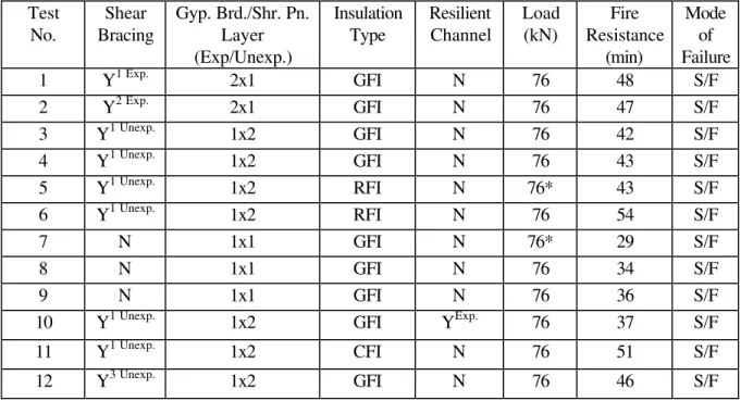
in North America and listed in the NBCC 2, but include plywood and oriented strand board (OSB) sheathing in addition to the gypsum board. The various details for each of the walls such as depths, number of layers of gypsum board, shear wall membrane and insulation are given in Table 1.
Table 1. Wood Stud wall Assembly Parameters and Fire Resistance Test Results Test Shear Gyp. Brd./Shr. Pn. Insulation Resilient Load Fire Mode
No. Bracing Layer Type Channel (kN) Resistance of
(Exp/Unexp.) (min) Failure
1 Y1 Exp. 2x1 GFI N 76 48 S/F 2 Y2 Exp. 2x1 GFI N 76 47 S/F 3 Y1 Unexp. 1x2 GFI N 76 42 S/F 4 Y1 Unexp. 1x2 GFI N 76 43 S/F 5 Y1 Unexp. 1x2 RFI N 76* 43 S/F 6 Y1 Unexp. 1x2 RFI N 76 54 S/F 7 N 1x1 GFI N 76* 29 S/F 8 N 1x1 GFI N 76 34 S/F 9 N 1x1 GFI N 76 36 S/F
10 Y1 Unexp. 1x2 GFI YExp. 76 37 S/F 11 Y1 Unexp. 1x2 CFI N 76 51 S/F 12 Y3 Unexp. 1x2 GFI N 76 46 S/F
All studs 89 mm and placed at a spacing of 400 mm
Y = Yes, N = No, S/F = Structural Failure Y1 = 12.7 mm Plywood, Y2 = 12.7 mm OSB, Y3 = 8.5 mm Plywood
GFI = Glass Fibre Insulation, RFI = Rock Fibre Insulation, CFI = Cellulose Fibre Insulation Exp. = Exposed Side, Unexp. = Unexposed Side, * Actual loads were 15-20% higher Shr. Pn. = Shear Panel, Gyp. Brd. = Gypsum Board Westroc “Fireboard” C/Type X
The wall assemblies were 3048 mm high by 3658 mm wide with various depths depending on the number of layers of gypsum board and shear membrane. A typical shear wall assembly is given in Figure 1. Type K chromel-alumel thermocouples were used to measure the temperatures at a number of locations throughout an assembly. The deflection at the unexposed surface was measured at 9 different locations. The wood stud shear wall assemblies were tested in a propane-fired vertical furnace in accordance with CAN/ULC-S101-M89 3. The load calculations were carried out based on the material characteristics of the wall. The applied loading on the wall assemblies used is given in Table 1. During the test, the furnace and wall assembly temperatures, deflections and the gauge pressure (of the loading system) were recorded at 1-minute intervals. The time to failure is based on failure criteria derived from CAN/ULC-S101-M89 3; i.e., thermal failure, integrity failure, or stability failure. Complete details on the construction of the wall assemblies, instrumentation location, and test procedures are given in References 4, 5.
RESULTS AND DISCUSSION
The results of the 12 full-scale fire resistance tests are summarized in Table 1 in which the time and mode of failure are given for each assembly. For all wall assemblies, the unexposed surface
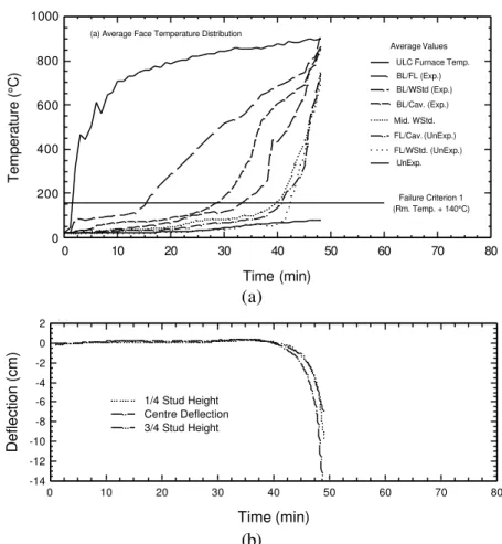
temperature at the time of structural failure was below the temperature failure criteria. All wall assemblies failed structurally through excessive deflection. The typical temperature distribution at the various locations in Assembly No. 1 is shown in Figure 2a, while the measured deflections are shown in Figure 2b. Detailed results, including temperatures and deflections measured during the fire tests on gypsum board protected, wood-stud shear wall assemblies, is provided in References 4 , 5. Results from the tests have indicated the 2 factors, which significantly influenced the performance of the wall assemblies, were the presence of the shear membrane and the type of insulation in the wall cavity.
Figure 1. Typical wood stud wall assembly with shear membrane on the fire exposed side
Time (min) 0 10 20 30 40 50 60 70 80 Temperature (°C) 0 200 400 600 800 1000 FL/Cav. (UnExp.) Mid. WStd. BL/Cav. (Exp.) BL/WStd (Exp.) ULC Furnace Temp. (a) Average Face Temperature Distribution
BL/FL (Exp.) (Rm. Temp. + 140°C) Failure Criterion 1 Average Values UnExp. FL/WStd. (UnExp.) (a) Time (min) 0 10 20 30 40 50 60 70 80 Deflection (cm) -14 -12 -10 -8 -6 -4 -2 0
2 (b) Deflection Measurements - Stud 6
3/4 Stud Height, Stud 6 (8) Centre Deflection, Stud 6 (5) 1/4 Stud Height, Stud 6 (2)
(b)
Figure 2. Typical measured temperature distribution and deflection for assembly No. 1 Effect of Shear Membrane
From Table 1, it can be seen that the fire resistance of the wall assembly with a shear membrane (Assembly 1) is 41% higher than the assembly without shear membrane (Assembly 8). This could be attributed to the additional stiffness provided by the shear membrane. Further, the presence of a shear membrane on the exposed side protected the studs, which in turn delayed the strength loss of the wall assembly. The presence of a shear membrane also enhanced the structural stiffness of the wall. The additional stiffness provided by the shear membrane delayed the deflection propagation in the wall, as compared to the wall with no shear membrane. The influence of a shear membrane on the fire resistance of wood stud shear walls is also shown in Figure 3a for tests 9, 4 and 1 for which structural failure occurred at 36, 43 and 48 minutes, respectively. The results show that the addition of a shear membrane in a 1x1 wall assembly increases the fire resistance, with the greater increase occurring when the shear membrane is placed on the exposed side of the assembly. The results also show that the wall with a thinner shear membrane provided slightly higher fire resistance as indicated by wall assemblies 3 and 12, which provided 42 and 46 min, respectively. This could be attributed to the positive benefit obtained from the enhancement of eccentricity (of load), resulting from the shifting of centre of gravity, which occurs due to the loss of cross sectional area of the stud. Further research is needed to determine the exact mechanism and to quantify the benefit of this effect.
Effect of Insulation Type
The type of insulation also played a major role on the performance of the shear wall assemblies exposed to fire. Results from fire resistance tests on Assemblies 3, 4, 6 and 11 can be used to indicate the effect of insulation types on the fire resistance of load-bearing wood stud shear walls (see Figure 3b). The failure of wall assemblies with the glass fibre insulation (3 and 4) occurred at 42 and 43 minutes respectively, while the failure of wall assemblies with the rock fibre and cellulose insulation occurred at 54 and 51 minutes, respectively. These results suggest that the use of cellulose fibre insulation provides a higher fire resistance compared to glass fibre insulation, but a lower fire resistance compared to rock fibre insulation. This can be attributed to the fact that when gypsum board at the exposed face fell off, the insulation was exposed to furnace heat. In the assembly with glass fibre insulation, the insulation melted and both sides of the stud and shear membrane were exposed to heat, while in the assembly with either rock fibre or cellulose fibre, the insulation remained in place and protected both the shear membrane and stud on both sides for an additional period of time. The rock fibre and cellulose fibre insulation played a significant role in limiting the temperature rise in the centre of the stud and shear membrane. This slow rise in temperature reduced the strength loss in the studs thus increasing its fire resistance. As the insulation remained in-place after the gypsum fell-off, it protected the plywood membrane on the unexposed side and consequently, enhanced the stiffness of the wall.
Shear Membrane Effect
48 43 36 0 10 20 30 40 50 60
No.1 No.4 No. 9
Assembly Number
Fire resistance (min)
Effect of Type of Insulation
42 43 54 51 0 10 20 30 40 50 60
No. 3 No. 4 No. 6 No. 11
Assembly Number
Fire Resistance (min)
Figure 3. Effects of shear membrane, its location and type of insulation
The influence of other parameters, such as the type of shear membrane, location of shear membrane, load intensity, and presence of resilient channels, on the fire resistance of wood stud shear wall assemblies are discussed in References 1, 4, 5.
COMPARISON OF MODEL PREDICTIONS WITH EXPERIMENTAL DATA
NRC, in collaboration with Forintek Canada Corp., has developed an analytical model for predicting the fire resistance of wood-stud wall assemblies 6. The model is based on observations from this and other sets of test data and couples a heat transfer sub-model and a structural sub-model. The heat transfer sub-model predicts the temperature profile inside the wood-stud wall and the time to insulation failure. The structural sub-model, based on the elastic buckling-load, uses the temperature profile to calculate the deflection of the wood studs and the time to structural failure of the assembly. At this stage of the development, the model predictions are limited to load-bearing wood-stud walls, protected by gypsum board only and does not include the effect of shear membranes. Therefore, analytical predictions will be carried out for those assemblies that do not contain any shear membrane.
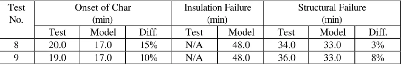
Fire resistance tests for assembly numbers 8 and 9 were used to evaluate the predictions by the fire resistance model. Details of the assemblies are shown in Table 1. Due to space limitation, the comparison figures will be shown for time to structural load failure and out-of-plane deflection for Test No. 8 only. The predictions of time-temperature curves generated by the heat transfer have been used to calculate the reduction in load carrying capacity of the studs and the degradation in the modulus of elasticity, which was assumed to be equal to 7000 MPa at ambient temperature. Temperatures on the unexposed sides did not reach the insulation failure criterion, as both assemblies failed by structural instability at 34 and 36 minutes for Tests 8 and 9, respectively. Table 2 summarizes the model predictions and experimental results. The model predicts conservatively the onset of charring, with a difference of about 15% for Test 8 and 10% for Test 9.
Table 2. Comparison of Tests Results and Model Predictions Onset of Char (min) Insulation Failure (min) Structural Failure (min) Test No.
Test Model Diff. Test Model Test Model Diff.
8 20.0 17.0 15% N/A 48.0 34.0 33.0 3%
9 19.0 17.0 10% N/A 48.0 36.0 33.0 8%
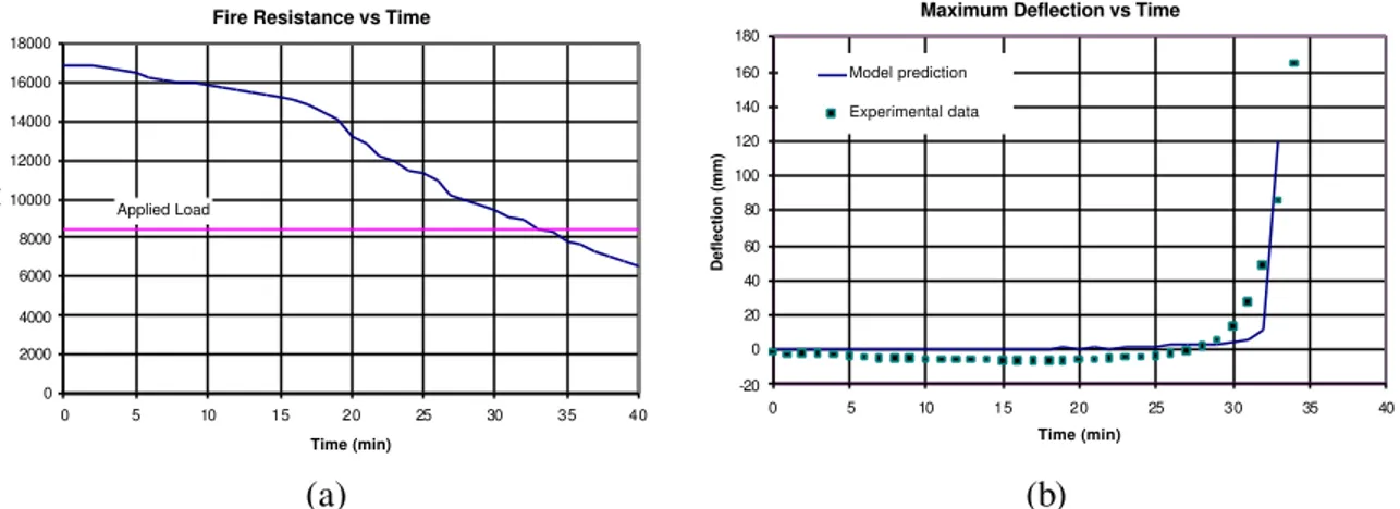
To measure the performance of the structural response model, the theoretical predictions of the structural fire resistance and deflection at mid-height are evaluated. Figure 4a illustrates the critical elastic buckling-load versus time as predicted by the structural response sub-model. The fire resistance decreases with increasing time because the value of the modulus of elasticity decreases with time and the cross-section of the studs reduces after charring. The intersection of the horizontal line, at the level of the applied load (8.45 kN), with the elastic buckling-curve, represents the theoretical time to structural failure of the wall. This time is 33 minutes, while the times to structural failure measured experimentally are 34 and 36 minutes for Tests 8 and 9, respectively. Therefore, the model predictions are very close to the test results, with the analytical time to structural failure slightly underestimated by 3% and 8% for Tests 8 and 9, respectively. Table 2 also shows a summary of the model predictions and experimental results for the two tests.
The mid-height deflections are also plotted versus time for both the analytical predictions and the test results (see Figure 4b). As shown in this figure, the deflection is very small in the first 30 minutes.
After this, the model predictions and the test measurements start increasing at a faster rate. The rate of increase in the model predictions is similar to that of the test results. The rate in the model, however, starts a few minutes later. The model slightly overestimates the deflection at 33 min.
Fire Resistance vs Time
0 2000 4000 6000 8000 10000 12000 14000 16000 18000 0 5 10 15 20 25 30 35 40 Time (min) Load (N) Applied Load
Maximum Deflection vs Time
-20 0 20 40 60 80 100 120 140 160 180 0 5 10 15 20 25 30 35 40 Time (min) Deflection (mm) Model prediction Experimental data (a) (b)
Figure 4. Fire resistance determination and deflection comparisons SUMMARY
Based on the experimental studies presented in this paper, the following points can be summarized: 1. For load-bearing wood-stud wall assemblies, the installation of a plywood/OSB shear membrane
increases the fire resistance of the assembly.
2. The maximum increase in the fire resistance of an assembly occurred when the fire exposure was on the same side as the shear membrane.
3. For load-bearing wood-stud shear walls, the assembly with rock fibre or cellulose fibre insulation provided more fire resistance compared to a similar assembly with glass fibre insulation.
In addition, a fire resistance model developed by NRC was used to show comparisons with the results of 2 experimental full-scale wall tests exposed to CAN/ULC-S101-M89 3 fire. The model indicates that the time to structural failure and lateral deflection of the studs at mid-height are reasonably well predicted. The current fire resistance model is suitable to assess the time to failure of load-bearing wood-frame wall assemblies for practical applications, using both the insulation and structural failure criteria.
REFERENCES
1
V.K.R. Kodur and M.A. Sultan, Performance of Wood Stud Shear Walls Exposed to Fire, Fire and Materials, Vol. 24, pp. 9-16, 2000.
2
National Building Code of Canada (Part 9), National Research Council Canada, Ottawa, 1995.
3
CAN/ULC-S101-M89, Standard Methods of Fire Endurance Tests of Building Construction and Materials, Underwriters' Laboratories of Canada, Scarborough, Ontario, 1989.
4
V.K.R. Kodur, M.A. Sultan, and E.M.A. Denham, Temperature Measurements in Full-Scale Wood Stud Shear Walls, Internal Report No. 729, Institute for Research in Construction, National Research Council, Ottawa, Canada, 1996.
5
V.K.R. Kodur, M.A. Sultan, J.C. Latour, P. Leroux, and R.C. Monette, Fire Resistance Tests on Cellulose and Glass Fiber Insulated Wood Stud Shear Walls, Internal Report No. 806, Institute for Research in Construction, National Research Council, Ottawa, Canada, 2000.
6
N. Bénichou, H. Takeda, M.A. Sultan, J.R. Mehaffey, "Modelling the fire resistance of loadbearing wood-stud wall assemblies," 4th International Scientific Conference on Wood and Fire Safety, Svolen, Slovakia, pp. 33-43, May 2000.