HAL Id: hal-02316841
https://hal.archives-ouvertes.fr/hal-02316841
Submitted on 15 Oct 2019
HAL is a multi-disciplinary open access
archive for the deposit and dissemination of
sci-entific research documents, whether they are
pub-lished or not. The documents may come from
teaching and research institutions in France or
abroad, or from public or private research centers.
L’archive ouverte pluridisciplinaire HAL, est
destinée au dépôt et à la diffusion de documents
scientifiques de niveau recherche, publiés ou non,
émanant des établissements d’enseignement et de
recherche français ou étrangers, des laboratoires
publics ou privés.
N-TWR: An Accurate Time-of-flight-based N-ary
Ranging Protocol for Ultra-Wide Band
Francois Despaux, Adrien van den Bossche, Katia Jaffrès-Runser, Thierry Val
To cite this version:
Francois Despaux, Adrien van den Bossche, Katia Jaffrès-Runser, Thierry Val. N-TWR: An Accurate
Time-of-flight-based N-ary Ranging Protocol for Ultra-Wide Band. Ad Hoc Networks, Elsevier, 2018,
79, pp.1-19. �10.1016/j.adhoc.2018.05.016�. �hal-02316841�
Any correspondence concerning this service should be sent
to the repository administrator:
tech-oatao@listes-diff.inp-toulouse.fr
This is an author’s version published in:
http://oatao.univ-toulouse.fr/22432
Official URL
DOI :
https://doi.org/10.1016/j.adhoc.2018.05.016
Open Archive Toulouse Archive Ouverte
OATAO is an open access repository that collects the work of Toulouse
researchers and makes it freely available over the web where possible
To cite this version:
Despaux, François and Van Den
Bossche, Adrien and Jaffres-Runser, Katia and Val, Thierry
N-TWR: An Accurate Time-of-flight-based N-ary Ranging
Protocol for Ultra-Wide Band. (2018) Ad Hoc Networks
Journal, 79C. 1-19. ISSN 1570-8705
N-TWR:
An
accurate
time-of-flight-based
N-ary
ranging
protocol
for
Ultra-Wide
band
François
Despaux
a,
Adrien
van
den
Bossche
a, ∗,
Katia
Jaffrès-Runser
b,
Thierry
Val
aa Institut de Recherche en Informatique de Toulouse, Université de Toulouse, UT2J Blagnac, France b
Institut de Recherche en Informatique de Toulouse, Université de Toulouse, INPT Toulouse, France
Keywords:
Ultra-Wide band Localization Wireless sensor networks
a
b
s
t
r
a
c
t
Inthelastdecade, wirelesspositioningsystemshavedrawnastrong interestfromaresearchpointof view,especiallyforindoorenvironmentswhereGlobalPositioningSystems(GPS)isnotavailable.Asan alternative,emergingapplications relying onUltra-Wide Band(UWB) communicationtechnologyhave beenproposed tooffer arangingaccuracy inthe orderofsomedozensofcentimeters. Indeed,UWB radios’increased accuracyoriginatesinthehightimeresolutionofUWBsignalsthatcanbeleveraged tomeasure precisely travel timesofsignals (e.g.TimeofFlight, ToF). ToFcan beeasily translated to inter-nodedistance. Inthiswork wepropose N-TWR,aToF-based N-aryranging protocolcreated for localizationusingUWB.TheproposedN-TWRprotocolisbasedontheestimationoftheToFbetweena targetnodetobelocalized(whichmaybemobileorstatic)andasetofNanchors.Ithasbeendesigned tominimizethenumber ofmessagesexchangedbetweenallnodescomparedtoanaivesolution that exploitsthestate-of-the-artUWBrangingmethod.Validationhasbeenmadeusingexperimentscarried outinourOpenSourceFramework,DecaDuino,whichenablesfastprototypingofprotocolssittingontop ofUWBPhysicallayer.TheN-aryrangingprovidedbyN-TWRachievesthesamelevelofaccuracyasthe naiveprotocolexploitingSDS-TWRbutusingfour timeslessmessages.WeexhibitaswellthatN-TWR canbeefficientlyleveragedtodesignasimpleandeleganttrilaterationlocalizationalgorithm.
1. Introduction
InthecontextofWirelessSensorNetworks(WSNs),and espe-cially in the context of mobile ad hoc networks (MANET), node localizationhas become utterlyimportantas moreandmore ap-plications rely on node positioning services, but as well for im-proved context-aware networkmanagement andmaintenance. As such, increasingattentionhasbeendrawnlatelyto wireless posi-tioning systemsin indoorenvironments whereGlobal Positioning Systems (GPS) usually fails. Several dedicated wireless technolo-gies have beenproposed. Alarge body of worksrely on the so-calledRF fingerprintingtechnique that measures thepower level receivedfromradiofrequency(RF)signalsemittedbywireless ac-cess points. The accuracy achieved by these techniquesis in the orderofseveralmetersusingWiFi[1] ,ZigBee[2] oreventensof metersformobilenetworks[3] .Moreover,anextensivesitesurvey hastobeconductedtocreatearadiomaptobeexploitedfor local-ization.WereferthereadertoSection 2 togetthemainsolutions oftheliterature.
∗ Corresponding author.
E-mail address: vandenbo@univ-tlse2.fr (A. van den Bossche).
Such aprecisionisunacceptableforapplicationsthat requirea precision inthe orderofafew tensofcentimeters. Wewillrefer to such a localization accuracyas a dozen centimeter-level accu-racy.Ultra-WideBand(UWB)communicationtechnologycombines medium tohighdataratecommunicationswithpositioning capa-bilitiesofferingarangingprecisionintheorderoffewcentimeters inalow-powerandlow-costcontext[4–6] .Forpositioningsystems employingUWBradios,time-basedschemesprovideverygood ac-curacyduetothehightimeresolutionofUWBsignals.These time-basedpositioningsystemsrelyonmeasurementsoftraveltimesof signalbetweennodes.TheIEEE802.15.4a-2007amendment[7] de-fines aphysicallayerforlowdataratecommunicationscombined withpositioningcapabilities.Oneofthecommunicationsignal for-matdefinedbythisstandardistheImpulseRadioUltra-WideBand (IR-UWB). Twodifferenttime-basedrangingprotocolsare defined by the standard: Two-Way Ranging (TWR) and Symmetric Dou-bleSided(SDS)-TWR.BothTWRandSDS-TWRsharetheobjective to estimate theTimeofFlight (ToF)betweentwo wireless nodes. ThedrawbackofTWRisthat thenontime synchronizationofthe internal clocks of the nodes is not compensated for, leading to inaccurate ToF estimations. SDS-TWR achievesToF measurements by accountingthe clockskewsintheToFcalculation,pushingthe
ranging accuracy to a couple of centimeters. However, this is achieved byperforming two timestheTWR procedurein a sym-metricmanner,doublingthenumberofexchangedmessages.
Thecontributionsofthispaperarebasedonourpreviouswork
[8]wherewe havedefinedanovelskew-awareTWRranging pro-tocol thatonlynecessitates 2messageexchangesinsteadofthe4 onesneededbySDS-TWR.
From thisimproved point-to-point ranging procedure,we de-velop an N-ary protocolcalled N-TWRthat efficientlyand simul-taneously ranges a staticor mobile target node from a set of N
anchor nodeslocated intheenvironment.Anchornodesarefixed andofcourse communicatewiththesameUWBphysicallayer.In other words, N-TWR measures the distances betweenthe target and a set of N anchor nodes.Compared to a naive implementa-tion triggering N successive pairwise SDS-TWR ranging steps, we show that N-TWRachieves the samelevel ofaccuracy withonly
N+1messagesinsteadof4×N.Thisleadstoanimprovedenergy performance,aswewillseeinthispaper.
OurN-ary rangingisparticularlyusefulforapplicationswhere movingitemshavetobetrackedpreciselyindoors.Anexample be-ing thetracking offooditemsduring their elaborationprocessin anautomatedfactory.Anotherexamplewouldbethedesignofan undergroundsmartparkingfacility.
The central contribution of this work is the definition of N-TWR,an on-demandlocalization protocolfor sensornodes.With thissolution,atargetnode caninitiatealocalizationoperationby communicating withN staticanchornodesdeployed in the envi-ronment.Thetargetnodelocatesitselfknowingthedistancesthat separatesherfromeachanchornodes.Distancesaremeasuredby leveragingourSkew-AwareTWRprotocol[8] .
The definitionof N-TWRhas leadusto develop thefollowing contributions:
• The definition of the Skew-Aware TWR protocol that estimates
the time of flight between two nodeswith a precision of a few centimeters.Thisestimate isobtainedby compensatingforthe clock skews using a reducednumber of exchanged messages. Twoalternativeimplementationsareinvestigatedfortheskew estimation: (i) using a linear regression approach and(ii) us-ingthehardwarefunctionalityofaspecificUWBtransceiver[9] , theDecaWaveDW1000.
• ThedesignoftheN-aryconcurrentrangingoperationsrequiredto producetheN-TWRlocalizationresult.Theseoperationsare real-ized using a specific TDMA protocolwhich facilitates the use of Skew-Aware TWR. We show that these operations lead to an accurate measurement ofthe distance betweenthe N an-chorsandthetargetnode. Thisprotocolisoptimalintermsof thenumberofexchangedmessagesasonlyN+1messagesare needed.
• The designof the trilateration algorithm. The N ranging results arehereexploitedbya specifictrilaterationalgorithm that lo-calizesthetargetwithanaccuracyofadozenofcentimeters. This paper is organized as follows: Section 2 presents the related works on localization using ranging protocols. The skew-aware TWR and the N-TWR protocols are presented in
Section 3 , together with our specific trilateration algorithm.
Section 4 presents our experimental results for the skew-aware TWR and N-TWR protocols and finally, conclusions and future worksaregiveninSection 5 .
2. Relatedworks
Thissectionintroducesfirstthemaintypesoflocalization pro-tocols capableof trackinga target node froma networkof static anchornodesdeployedindoors.Next,thediscussionfocusesmore
specificallyonsolutionsrelyingontimeofflightmeasurementand UWBranging.
2.1. Positionestimation
2.1.1. ReceivedSignalStrength(RSS)
Thestrengthofareceivedsignalisdecreasedbypathloss(PL) whichisproportionaltothedistancebetweenemitterandreceiver. Assuch,measuringRSScanbeleveraged toestimatethedistance from a target node to an anchor node. Using a basic free-space pathlossattenuationmodel,theRSSmatchesP¯
(
d)
asfollows:¯ P
(
d)
=P0−10nlog10µ
d d0
(1)wherenisthePLexponent,P¯
(
d)
isthereceivedpoweratdistancedandP0isthereceivedpoweratreferencedistanced0.By
model-ingbothmulti-pathandshadowingphenomena[10] ,theCramer– Raolowerbound(CRLB)[11] givesanestimateofthedistance be-tweenthetargetandtheanchornode.Itisthenpossibletoderive theuncertaintyofthetarget positiongivenby acircularshapeof centre C (anchor position) and radius d. A finer position can be calculatediftheRSSofseveralanchornodesismeasured,creating severalcirclesontheplanewhoseintersectionhelpinreducing lo-cationuncertainty.ManypapersdealwithRSSlocalization[12,13] ...
2.1.2. TimeofArrival(TOA)
TheTimeofArrival[14] methodestimatesthedistancebetween atargetandanchornodeforwhichthepositionisknown.The dis-tancebetweenbothnodescanbederivedfromthetimeofarrival
τ
andthepropagationspeedofthesignalc.Sincethedistance es-timationisbasedonthetimeofarrival,ananosecond synchronisa-tionbetweentargetandanchorclockismandatoryasasmalltime measurement errortriggers large distance deviations.As for RSS, thelocationofthetarget nodecan bedeterminedwithincreased accuracyifthetimeofflightofseveralanchornodesiscomputed, materializedbytheintersectionofcirclesofdifferentcentersand radii.2.1.3. TimeDifferenceofArrival(TDOA)
PreviouslyintroducedTOAapproachimposes afine synchroni-sationbetweentargetandanchornode.Adifferentapproachthat does not requirea separate clock synchronisationbetweentarget andanchor node is known asTime Difference ofArrival (TDOA)
[14] . The TDOA technique measures the time ofarrival of an RF signal fromthetarget atseveralpoints in spacegivenby the lo-cation of the anchors. The method compares the dates each an-chornodehasreceivedthesignalofthetarget.Thetraditional ap-proachtoestimatingTDOA istocompute thecross-correlation of a signal arriving at two nodes. By knowing the location of each receiver(anchor),an estimateofthelocation ofthesourceofthe emissionscanthenbededucedbyintersectingasetofhyperbolas. Eventhoughthere isno needforsynchronisationbetweentarget andanchors, thismethod imposes receiver nodesto be synchro-nized.
2.1.4. AngleofArrival(AOA)
The Angle of Arrival (AoA) [14,15] technique, sometimes re-ferredtoasDirectionofArrival(DoA),locatesthemobilenodeby determiningtheangleofincidenceatwhichsignalsfromthe tar-getarriveatthereceivingnode.Geometric relationshipscanthen beusedtoestimate locationfromtheintersectionoftwo linesof bearing(LoBs)formedbyaradiallinetoeachreceivingnode.Ina two-dimensional plane,at leasttwo receiving nodesare required for location estimation with improved accuracy coming from at leastthreeormorereceivingnodes(triangulation).
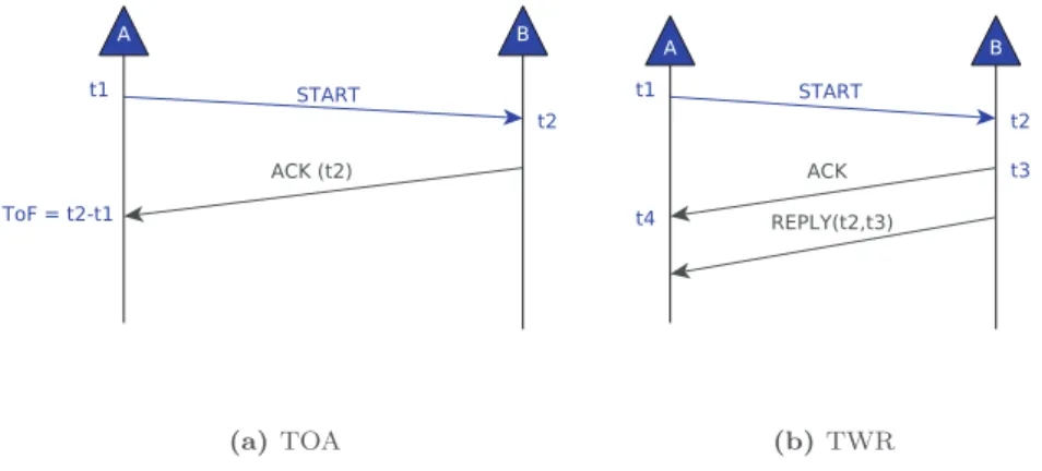
Fig. 1. TOA and TWR protocols.
2.2. Rangingprotocols
Ranginggivesan estimateofthedistancebetweentwonodes, the radius. This information can be deduced from the received powerofsignalsemittedby anchorsorbymeasuring thetimeof flight.Thefirstoptionoffersatbestameter-levelrangingaccuracy whiletheotheronecanrangeanode withanerrorofonlyafew centimeters.Mainsolutionsforbothstrategiesarepresentednext, withanemphasisgiventotimeofflight-basedsolutions.
2.2.0.1. Rangingwith Received Signal Strength Indicator (RSSI). The firstrangingsystemswerebasedonRSSImeasurementsasRSSIis offeredbymostradioplatformstotheupperlayersoftheprotocol stack. In thecontext of WSNs, severallocalizationsystems based onBlueToothLowEnergy(BLE)[16] havebeenproposed:BlueCats, BlueSense,Estimote,Gelo,GlimWorm,Kontakt,Sensorberg,among others. They all build on the initial solution proposed by Apple and known as iBeacons [17] . They hardly provide a meter-level accuracy for ranging asBLE beacons reception power is strongly influenced by obstacles (walls, humanbody,etc.). A recentstudy
[18] highlights that iBeacon RSSI values vary significantly across iBeacon vendors, mobile device platforms, deployment height of the device, indoor/outdoor environmental factors, and obstacles. Another recentfield study achievesa meter-level localization ac-curacybycombiningBLEwithWiFifingerprints[19] .
2.2.0.2. RangingwithTimeofFlight(ToF). ToF-basedprotocols com-putethedistancebymultiplyingtheToFbythepropagationspeed. Asexplainedbefore,inTimeofArrival(ToA),anode(target)sends amessagetoananchor.Thetargetnodemarkstheemissiontime of thismessage. Oncereceived, the anchor recordsthe reception time andsends thisinformationbackto thetargetnode whocan estimatetheToFbysubtractingbothtimestamps.Fig. 1 (a)pictures theToAprotocol. Thissimpleapproachrequires,however,a com-monnotionoftimebetweennodes.Inotherwords,a synchronisa-tionbetweennode’sclocksismandatory.Someresearchesinthis directionwereproposedin[20] and[21] .
The conventional two-way ranging protocol (TWR) [7] , esti-matestherangewithoutacommontiming reference.Inthis pro-tocol(Fig. 1 (b)),targetnodesendsaSTARTmessagerecordingthe departuretimet1.Oncethismessageisreceivedbyananchor,the
anchorrecordsthearrivaltimet2 andsendsthecorresponding
ac-knowledgement(ACK)backtothetarget,recordingalsoits depar-turetimet3.AfterreceivingtheACKmessage,thetargetnodewill
alsorecord the arrivaltime t4.Due tothe inabilityforpredicting
theACKdeparture time (andthusthe inabilitytoembedthis in-formation inthe ACKresponse), a second message REPLY is sent backtothetargetnodecarryingtheinformationspecifyingt2and
t3. Withthisinformation atthetarget node side, the ToFcan be
computedasfollows:
ToF=t4−t1−
(
t3−t2)
2 (2)
An improvementofTWR, named2M-TWR(2-Messages TWR), was proposed in [22] . In this protocol, depictedin Fig. 2 (a), au-thors make use of a functionality of the DecaWave DW1000
[9]transceiverthatallows toscheduletheemissionofaframe at aprecisetimewithaprecisionof15picoseconds.Theframe send-ing instant isalignedona 8nstimeslot, whichisa limitation of the hardware.Thanks tothisfeature,the MAC-layerhasthe abil-ity togeneratea frame whichincludes its futuredeparture time. Then,botht2andt3canbeembeddedintheACKresponse,
reduc-ing then the number ofmessages sent since the REPLY frame is nolongerneeded.Thissolutionkeepsasimilarandanacceptable rangingerror.
One ofthemainsources oferrorinTWRprotocolstems from the clock skew. Crystal oscillators used in sensor nodes do not work exactly withthe same nominalfrequency. As such, a small positive or negative relative offset accumulates over time. Since propagationspeedisalmostthespeedoflight,evenasmalloffset may causea significant error inranging. TheSymmetric Double-Sided TwoWay Ranging (SDS-TWR) shownin Fig. 2 (b)was pro-posed in the UWB standard [7] to mitigate the impact of clock skew. BymeansoftwosubsequentTWRsteps,itreducesthe im-pact of clock skew on the ranging results. The ToF can then be computedas:
ToF=
(
t4−t1)
−(
t3−t2)
+(
t8−t5)
−(
t7−t6)
4 (3)
UnliketheTWRalgorithm,SDS-TWRalgorithmneedsatleast4 messagestogetranginginformation.Besides,andinorderto elim-inate theeffects of clock skews,it assumes that theturn-around timeofsenderAisthesameastheturn-aroundtimeofreceiverB
(i.e.
1
A=1
B inFig. 2 (b)).Subsequently,differentvariantsoftheSDS-TWRhavebeen pro-posed in the literature. In [23] , authors propose the SDS-TWR-Multiple Acknowledgement (SDS-TWR-MA) in which the anchor sends multipleACK framesfor a singleSTART message fromthe target node (cf. Fig. 3 ). Thebasic ideabehindthe proposed algo-rithmistousemultipleacknowledgementmessages(ACK+REQ)for a single rangingoperation instead ofiterating thewhole ranging process severaltime to geta stabler rangingresult. According to their results,their rangingalgorithmreducesthenumberof rang-ingmessagesof33%comparedtotheSDS-TWRprotocol.
In [24] , authors propose Double Two-Way Ranging (D-TWR) protocolforestimatingtheToF,reducingtheeffectsofclockskews without the assumption of identical reply time between node A andB(Fig. 4 ).NodeAstartstherangingbysendingaSTART mes-sageand,afterafixeddelay
τ
A,asecondmessageissenttonodeFig. 2. 2M-TWR and SDS-TWR protocols.
Fig. 3. SDS-TWR-MA protocol [23] .
Fig. 4. D-TWR protocol [24] .
B. By using a fixed time delay, the reply time of each device is nolongerneeded.ResultsshowthatD-TWRcanreducethe num-berofrangingmessageswhencomparedtoSDS-TWR.Asfaraswe know,theD-TWR protocolisnot implementableontoday’sUWB transceivers, where the emisssiontime cannot be scheduled ex-actlyatpicosecond-level.
Authors in [25] , propose an SDS-TWR version which is able toreduce the rangingerrorwhen thevariation ofthe replytime or the values of timing drift increases. Their idea is to intro-ducea compensationfactorfora pairoftwosensor nodesbased on broadcasted information. During SDS-TWR operation, the re-plytime
1
is sentto itsnext sequentiallytransmittingnode and basedontheratioofthetwodifferentreplytimes,individualnode willthencalculateacompensationfactoranduseittocompensate rangingerrorduetothevariationofthereplytime.Eventhough SDS-TWR clearly reduces the negative impact of clock skews, it necessitates an important number of exchanged messages,an issuethatmaybeprohibitiveforenergy-constrained applications. The goal of all previously presented works is to presentarangingprotocolthatprovidesthemostaccurate instan-taneousrangingmeasurement.Hence,protocolsthatperform bet-ter are usually exchanging more information. In this work, and contrarilyto this, we leverage a ranging protocolthat minimises the numberof exchanged messages but that is still accounts for clockskewstopreserverangingaccuracy.
In Section 3.1 , we offer a detaileddescription of Skew-Aware TWR, a ranging solutionwe havedefined in ourprevious works
[8] .WeshowinthispaperthatthisprotocoloffersanaccurateToF estimationasit compensatesfortheclock skews witha reduced numberofmessageexchangescomparedtoregularSDS-TWR pro-tocols. Next,we introduce the novel N-TWRlocalization protocol basedonSkew-Aware TWRtooperateconcurrentlyNranging op-erationsbetweenatargetnodeandNanchornodes.
N-TWRiscomparedbyextensivemeasurementstosolutions re-lying onSDS-TWR inSection 4 . Next,we present an overviewof theIEEE802.15.4astandardasitiscentraltoourdesignandisthe oneusedinourexperiments.
2.3.Background:Standard802.15.4a
The IEEE 802.15.4a [7] is the first international standard that provides a specific physicallayer capable ofwireless ranging for WirelessSensor Networks.Two formatsof communicationsignal areproposed:ImpulseRadioUltra-WideBand(IR-UWB)signaland thechirp spreadspectrum (CSS)signal,both ofthemsuitable for datacommunicationaswellasrangingpurposes.Inthiswork,we
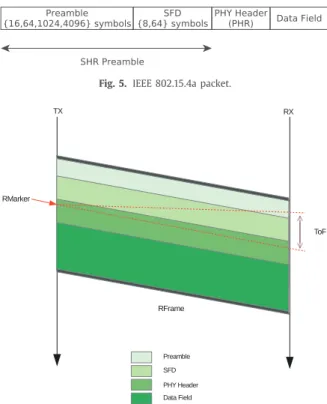
Fig. 5. IEEE 802.15.4a packet.
Fig. 6. Ranging support in IEEE 802.15.4a packet.
considerthe IRsignalformat. Thepacketformat proposed bythe standard isshownon Fig. 5 .Thepacketpreamble isusedto syn-chroniseentitieswithinformingarrival ofapacket.Thepreamble lengthisof16,64,1024or4096symbolsandisadjustedto chan-nelqualityforanincreasedreliability.Forexample,alarger pream-blesizewill helplow qualityreceiversto gainhigherSNRswhile asmallerpreamblesizereducesthechanneloccupancy,leadingto amoreefficientenergyconsumption.TheSFDisashortsequence with8or64symbolsindicatingtheendofthepreamble andthe startofthephysicallayerheader.Itisusedtoestablishframe tim-inganditsdetectionisimportantforaccuratetimeestimation.
According to the standard, a device may implement the op-tionalrangingsupportbyspecifyingaRFRAMEframeaspresented inFig. 6 .TheRFRAME isindicated by settingaranging bitinthe PHYheaderofthepacket.Therangebetweentwonodes(devices) isdetermined typicallyviaTimeofArrival(ToA) (seeSection 2.2 ) of a RFRAME by tracking its arrival time. However, as seen in
Section 2.2 ,ToArequiresacommontimebasebetweenbothnodes. As such we exploit here TWR which is less sensitive to relative clockoffsets(Fig. 1 (b)).
Twocountervaluesarenecessarytoreport:therangingcounter start value, whichrepresents thetime ofarrival (ToA) (t2) ofthe
firstpulseofthefirstsymbolofthePHR,alsoknownasRMARKER, and the ranging counter stop value representing the time when theRMARKERoftheACKpacketleavestheantenna(t3).Then,the
timestamp report should contain both (t2) and (t3). This
times-tamping requiresa veryhighprecision timer, typically more pre-cise than 100 ps, whichis available ontoday’s UWB transceivers suchastheDecaWaveDW1000[9] .Onthistransceiver,the resolu-tionofthehighprecisiontimeris15.625ps(64GHz),which the-oreticallyenablesaprecisionof4.69 mmonrangingoperations.
2.3.0.3. AnoteonUWBtransceiverselection. Toevaluatethe perfor-mance ofour solution,we willconduct an extensiveexperiment campaign. Thisexperimental validationensures that
(
i)
the oper-ationsarefeasibleonalightweightsensor,(
ii)
theobtained accu-racyaccountsforarealisticsetting.The rangeofUWBhardware currentlyavailable isvery limited asonlyafewdifferenttypesoftransceiversaresoldonthemarket. WehaveconductedourexperimentswiththeDecaWaveDW1000
[9]transceiver.Sincethissensorplatformisnotavailable inopen WSN testbeds,we’veconductedourmeasurements withourown platform as described in Section 4.1 . This transceiver offers ad-vancedfunctionalitiesthatmaybeleveragedtoincreasethe accu-racy ofrangingoperations.However, theprotocolsdefinedinthis paperdon’trequiretheseadvancedfeaturesandthus,areportable toothertypesofplatforms.Theonlycharacteristicrequiredfor se-lecting another transceiveristo be ableto record message emis-sion andreception dateswith aprecision in theorder oftens of nanoseconds.
Advancedhardwarefunctionalitiesareforinstance
(
i)
the abil-itytolearntheclockskewbetweentwonodesengagedina rang-ingoperationasleveragedin[26] ,orii)theabilitytoschedulethe emissionofaframeataspecificfuturedateasleveragedin[8] .If such features areavailable,it ispossibletoimprovetheprecision of the protocols proposed herein orreduce the number of mes-sagesrequired.3. N-TWR:Anoveltime-of-flightlocalizationprotocol
As said, time-based positioning systemsrely onthe measured travel timesofsignalsbetweennodes.Ourobjectiveinthiswork is to providean accurate Time-of-Flightbasedlocalization proto-col (N-TWR) wherea target node can accuratelyestimate its po-sition using a reduced number of messages exchanged with N
anchor nodes. Localization of the target necessitates the estima-tion of the range separating the target node from each anchor node. This ranging operation can be performed naively by real-izing N basic SDS-TWR operations. Instead, our N-TWR solution elegantly leverages ourSkew-Aware TWR [8] protocoltoperform the Nrangingoperationsandcalculatethelocationoftheanchor accordingly.
This section describes the N-TWR protocolby first describing thefeaturesofSkew-Aware TWR.Next,itdefineshowN-TWR op-erates andcalculates thetargetlocation fromthe Ntarget-anchor ranges. Note that all operationsperformedinN-TWR can be im-plementedontoday’sUWBtransceivers.
3.1. Skew-AwareTWRranging
TheproposedapproachisbasedontheTWRprotocol.Asshown inFig. 1 (b),oncethemessagereplyreachesthedestination,node
A will be able to estimate theToF asin Eq.(2) .However, t4−t1
andt3−t2arevaluesthatarecomputedbydifferentnodeshaving
different clock rates. Hence, thetime differencet3−t2 measured
with the clock rateof A andt4−t1 withthe clock rate of Bare
reallydifferent,eventhoughthey representalmost thesametime interval. Authors in[26] propose a skew compensationbased on a DecaWaveDW1000 functionalitythat allows obtaining the fre-quency relationship betweennodes: k= fB
fA.Then, theestimation
oftheToFbytakingintoaccounttheclockskewcanbecomputed asfollows:
ToF′=t4−t1−k
(
t3−t2)
2 (4)
However, this approach is platform-dependent in the sense that itreliesontheDecaWaveDW1000functionalityforcompensating theskew.
In ordertobe ableto estimatethe skewforanytype of plat-form,wehaveproposedin[8] anotherapproachwhichdoesn’t de-pend on a specific hardware functionality. It proposes a method based on linear regression that allows us to estimate the skew value K. Linear regression solution is obtained using the least
Fig. 7. Skew estimation.
squares methodology[27] provided by theSciPy scientific library
[28]forPython.
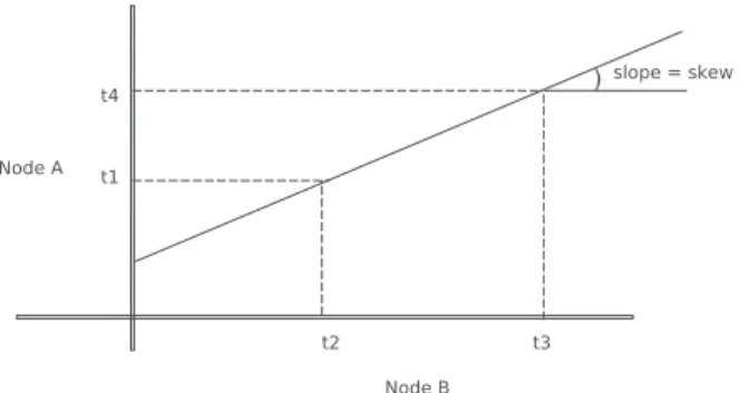
From the message exchange shown in Fig. 1 (b), node A re-ceives t2 andt3 representing thedates thefirst pulseofthefirst
symbol of the PHR of the START message (RMARKER) arrives at node BandthemomentwhentheSFDmarkeroftheACKpacket leaves the antenna, respectively. This information is very useful for node A toestimate the skew ofnode B withrespectto node
A. This can be done as shown in Fig. 7 where the line’s slope represents the skew between node A and B.This first TWR iter-ation will allow node A to obtain a first rough estimate of the skewbetweenitselfandnodeB,basedonthelinepassingthrough points (t2, t1) and(t3,t4). Successive message exchanges will
al-low node Ato estimatea moreaccurateskew bymeans ofa lin-ear regression approach which will consider, not only, the cur-rent points (t2, t1) and (t3, t4), but also those previously
com-puted. Bysuccessivelycomputingtheslopeoftheregressionline, the estimation of the ToF can be improved in the same way as donein[26] butusingtheslopelearnedwiththelinearregression method:
ToF′′=t4−t1−slope
(
t3−t2)
2 (5)
Animportantpointtoemphasizeisthefactthatourlinear regres-sion approach approximates the skew by considering two points (t2,t1) and(t3,t4)anditassumestheglobalinstantst1 andt3 to
beequaltot2 andt4,respectively.Inotherwords,thepropagation
time isneglected.Thisassumption isnotunreasonablegiventhat the propagation time isaround 9nanoseconds (for a distance of 2m) while
(
t4−t1)
and(
t3−t2)
are around300µ
s. Clearly,theimpactofthesefewnanosecondsovertheskewcanbeconsidered asnegligible.
It is importantto stress aswell that thenumber ofmessages sent with Skew-Aware TWRis ofatmost threeandat leasttwo ifACKandREPLYaremergedusingtheschedulingfunctionalityof
[22] ,whichisatwo-folddecreasecomparedtoSDS-TWR. Another important point is the channel access mechanismof Skew-Aware TWR. Every time a node has a message to send (START,ACK,REPLY),itsendsitasdoneinAlohamethod.Inother words,thereisnoadvancedaccesscontrolforsendingtheseUWB frames. Since inthiscase,only twonodesemit messages one af-tertheother,thereisnoriskforcollisionsamongtheseframes.By means ofthis scheme,we avoiddelayingthe receptionof times-tamps (which may have a non-negligible impact in the ToF and thus,intherangingestimation).
In Section 4 , experiments show how the accuracy on the es-timated ToF is improved for Skew-Aware compared to the basic TWR protocol. An experimental comparison of Skew-Aware TWR with SDS-TWR is presentedas well, showingthat both protocols offer thesame levelofranging accuracy.Skew-Aware TWR being
particularly energy-efficient and precise, we have leveraged it to deriveourN-TWRN-aryrangingprotocolpresentednext.
3.2.N-TWRrangingprotocolandlocalizationalgorithm
Inthissection,we presentthe proposedN-TWRN-ary ranging protocol that builds on our improved Skew-Aware TWR scheme. TheaimofN-TWR istocompute withalimitednumberof mes-sageexchangesthedistancebetweenthetargetnode andasetof
Nanchornodesdistributedinthebuilding,concurrently.Basedon therangingmeasurements,weintroduceanovellocalization algo-rithmthat,knowing theanchorlocations,derivesthetarget posi-tion.
3.2.1. N-TWR
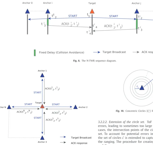
Fig. 8 shows the sequence diagram of the proposed protocol. ThetargetnodestartsbybroadcastingaSTART packet(violet seg-ment)recordingitsdeparturetimet1.Oncethebroadcastmessage
arrivesatanchorAi,itrecordsitsarrivaltimeti
2andsendsbackan
ACKmessage(greyline)atti
3.
Ifthe transceiverisable to schedulethe emissionof message (cf.Fig. 2 (a)),theACKmessagecanholdbothti
2andt3i timestamps.
FortheDecaWaveDW1000platform,the transmissiontime reso-lutionisof15.625ps;Theemissioncanbescheduledatthe begin-ningofan8nstimeslot.Thankstothisfeature,theMAC-layerhas theabilitytogenerateaframewhichincludesitsfutureemission date.
Once the target node receives the ACK message from anchor
Ai, itrecords its arrival timeti4. From t1,t2i, t3i andti4, the target
node computes the ToF fromitself to anchorAi using the linear
regression skew compensation ofSkew-Aware TWR presented in
Section 3.1 . The same calculation is applied to obtain the range separatingthetarget fromtheotheranchors.Fig. 9 illustrates the proposedN-aryprotocol.
In our experiments, and in order to avoid collisions, a deter-ministic delaydbetweenAi andAj ACKmessagesisenforced,
∀
i,j,i6=j.TheideabehindthisschemaistoimplementastaticTDMA whichisdeterminedbasedontheanchor’saddresses.The anchor havingtheloweraddressvalue, andafterafixed delay,sends the responseback to thetag inthefirst place.The second lower ad-dressanchorwillthenwaitforthefirstmessageandwillsendits response atits assigned slot.The procedure is then executed for allanchors.Thesedelaysarerepresentedinthesequencediagram (Fig. 8 ,green rectangle). Oncethe target node hascomputed the ToFfrom itself to each ofthe anchors, it will be able to findits positionusingtheknownlocationsoftheanchorswithagiven lo-calizationalgorithm.
ThankstothebroadcastoftheSTARTmessage,N-TWRreduces the number of messages neededto poll n anchors. By using N-TWR, the whole ranging process is completed in a shorter time than classical ranging protocols, typically few milliseconds, de-pendingonthenumberofanchors.Thisdurationisconsistentwith usualdutycyclesvaluesconsideredinWSNs:forarangingperiod ofonesecond,thedutycycleislowerthan1%.Themessage num-berreduction,combinedwiththelimitedrangeofUWB transmis-sion, has another benefit: it offers good scalability properties to N-TWR.Onlya limitednumberofanchors will receivetheinitial START messageandparticipateto thelocalizationoperation. This localizationoperationonlylastsacoupleofmilliseconds.Assuch, it is reasonable to think that several target nodes could request forlocalizationwithN-TWR.However, howto orchestrateseveral localizationrequestsconcurrently isnotinvestigatedinthispaper andiskeptforfutureworks.
Nextwepresentthespecifictrilaterationalgorithmusedinthis worktolocalisethetargetnode.
Fig. 8. The N-TWR sequence diagram.
Fig. 9. The N-TWR protocol.
3.2.2. Localizationalgorithm
In order to validate the N-TWR N-ary ranging protocol pre-sentedintheprevioussection,wehavedesignedaspecific trilater-ation algorithm.Thisalgorithmlocalizesthe targetnode knowing theanchornode locationsandtherangesmeasuredwithN-TWR. From N-TWRranging,thetarget nodescomputesthe distancesto eachanchorfollowing:
dist<t,i>=
v
×ToF<t,i> (6)beingToF<t,i> thetimeofflightfromthetargetnode ttoanchor
i,andv thepropagationspeed. Withthisinformation,a setof N
circles C=
{
C1,C2,...,CN}
of center(xi,yi) andradius ri arecon-structed, where(xi, yi) represents theposition ofanchor i andri
therangedist<t,i> betweenthetargetandanchori.Inour exper-iments,weconsiderthreeanchorsandthesizeofthesetC isthus equalto3(N=3).Thepositionofthetargetbelongstothesurface intersectingallcirclesinC.
3.2.2.1. Main localizationsteps. Our trilateration algorithms works in the following manner. First, from the set of circles C defined withcenterandradius,wecomputethesetofintersectionpoints Pwherethecirclesintercept.Anintersectionpointisaddedtothis setifitbelongstoatleasttwocircles.FromthissetP ,thelocation ofthetargetnodeSisderivedasthecentreofmassofallpointsin P. Thislast calculationofS isdevelopedlaterforthecasewhere
N=3.
Fig. 10. Concentric Circles { C i r } for a given anchor i .
3.2.2.2. Extensionofthecircleset. ToFmeasurements areproneto errors,leadingtosometimestoolargeortoosmallcircles.Insuch cases,theintersectionpointsofthecirclesofC maybe anempty set. To account for potential errors in the localizationalgorithm, thesetofcirclesCisextendedtocapturepotentialimprecisionsin the ranging.The procedureforcreatingthisextendedset isgiven asfollows:
For each Ci∈C, we consider the set of k+1 concentric cir-cles Ci=
{
Cri
}
where r represents the radius taken from the setofR=
{
ri,ri+k,ri+2k· · ·ri+k2}
.Inotherwords,weconsidertheoriginal circle ofradius ri andthose formed by incrementing its lengthfromritori+k2withan increment ofk units.Fig. 10 shows
theconcentriccirclescreatedfromagivencircleCi.
The extended set ofcirclesis composed ofthe setof all con-centriccirclesderivedfromtheoriginalcirclesinC.
3.2.2.3. Target location derivation for N=3. The following algo-rithmisdefinedfor
|
A|
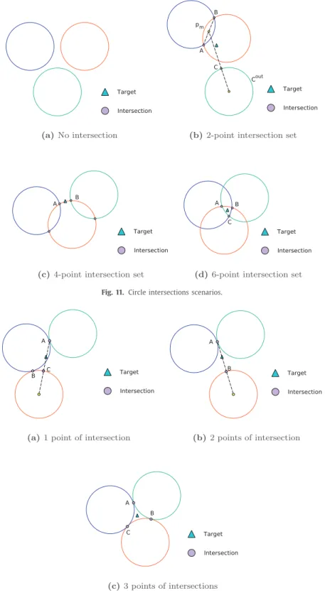
=3(i.e.wehavethreecirclestointercept) toextractthelocationofthetargetnode fromthesetof intersec-tionpointsP.ItisillustratedinFig. 11 .Theintersectionprocedure calculatesthecoordinatesoftheintersectionpoints.Dependingon thelocationandsizeofthecircles,adifferentnumberof intersec-tionpointscanbeobtained.Forthecaseof|
A|
=3,fourcasesare depictedthataresolvedasfollows:• NointersectionpointsFig. 11 (a)Nosolutionexists-S=∅. • Two-point intersection set (Fig. 11 (b)): In this case, P=
{
A,B}
andthereis onecircle, Cout which doesn’tinterceptanyother
circle.ThepointS isobtainedasfollows.First,themidpointpm
of [A, B] segmentis calculated.Then, the segments=[pm,c],
withc thecenterofCout,isconstructed.ThesolutionS is
ob-tainedby findingthe centerofmassofA,BandCwhereC is theintersectionofsegmentsandCout.
• Four-pointintersectionset(Fig. 11 (c)):Inthiscase,the intersec-tionsetholds4points.Thesolutionisthenobtainedby select-ing firsttheclosest pairofpoints (A andB).The locationS is
Fig. 11. Circle intersections scenarios.
Fig. 12. Circle intersections scenarios (particular cases).
defined asthe middlepoint of thearc whose extreme points areAandB.
• Six-point intersection set (Fig. 11 (d)):In this case, P holds six points. The locationS isobtainedby computingthecentreof massoftheclosesttripletofpoints(A,BandC).
Besides, threeparticularcasescan alsobeidentified asshown inFig. 12 .Here,Fig. 12 (a)and(b)areparticularcasesofFig. 11 (b), whileFig. 12 (c)isaparticularcaseofFig. 11 (d).
Consideringthefactthatthetargetnodehasalltheinformation regardingthe anchorpositions aswell asthedistanceto each of them,the previouslypresented procedureforintersecting the set ofcirclescanbeeasilycomputedbythetargetnode.
Moreover,wehaveillustratedthecomputationofSforthecase whereN=3.Weshowthatthiscaseperformsverywellinour ex-perimentsin nextsection. We candevelop a localizationstepfor largerN,butthefact thatN-TWRworkswell for3anchors is re-allyinterestingasitoffersinterestingscalingproperties.Indeed,if
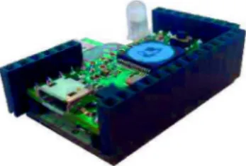
Fig. 13. DecaWiNo: Deca-Wireless Node.
T targets want to localizethemselves concurrently and there are
N>>T anchors available for servicing these requests,
⌊
N/T⌋
re-quests could be performed inparallel at most. Ofcourse, proper schedulingandanchortotargetassignementshavetobearranged by ahigherlayerprotocol.Thisfeatureisout ofthescope ofthis paperandleftforfutureworksbutprevious researchhas demon-strateditsviabilityforotherlocalizationtechnologies[29,30].4. Experiments&results
In this section, experimental results are given to validate the performanceofthepreviouslypresentedprotocolsandalgorithms. First, a description ofour testbed isgiven. Second, we introduce a setofexperimentalscenarios forwhichwe cantest the perfor-mance ofthe Skew-Aware TWR protocol ofSection 3.1 . In order toaccuratelycarryoutthisexperimentalevaluation,apreliminary experimenthadbeendonewhoseobjectiveistodeterminethe im-pactoftheantenna’sorientationsontheestimatedToF.Basedon these preliminary results, experiments were carried out to com-pareSkew-Aware TWRtobothTWRandSDS-TWR.Finally,the N-TWRprotocolhasbeenexperimentedtogetherwiththeresultsof ourtrilaterationlocalizationalgorithm.
4.1. Testbeddescription
The testbed is based on DecaDuino [22] , an open framework for the fast-prototyping and performance evaluation of UWB-based protocols. It provides a driver for the DecaWave DW1000 UWB transceiver and modules based on this transceiver, such as DecaWave DWM1000. In addition to wireless communica-tion, DecaDuino supports ToF ranging. As a classical Physical-layer Service Access Point (PHY-SAP), DecaDuino provides the two conventional Physical-Data (PD) and Physical Layer Manage-ment Entity (PLME) SAPs which enable MAC-level protocols to send/receive data and configure the transceiver (channel, trans-mission rate, preamble parameters...). Since this framework was designed to aid in the implementation of ToF based protocols, DecaDuino alsoprovidesaccesstothePhysical-level 64GHzhigh precision timer which offers precise message timestamping at both transmission (tTX) and reception (tRX) with a resolution of
15.625 ps. Finally, DecaDuino implements advanced synchroniza-tion/timestampingfunctionalitiessuchasdelayedtransmissionand receiverskew evaluation. Acomplianthardware calledDecaWiNo isalsodescribedin[22] andshowninFig. 13 .Onthisdesign,the transceiveris aDWM1000[9] andtheArduinoboardisa Teensy 3.2whichembedsanARMCortexM432-bitMCUratedat72MHz, with64kBRAMand256kBprogrammemory.DecaWiNofollows an openhardware design;variousressourcesonthisnodecan be found at [31] .There is no specific operatingsystem deployed on themicro-controller,allprotocoloperationsbeingimplementedin C.
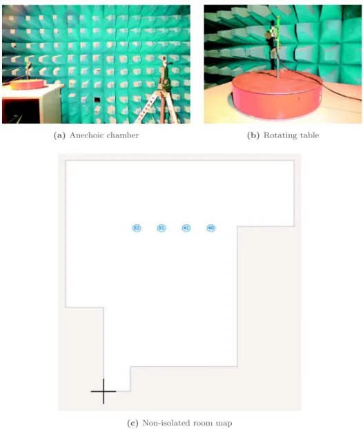
Measurements have been done in two different types of en-vironments: an anechoic chamber and a non-isolated room de-picted inFig. 14 (a)and(c), respectively.As seen onthe map, re-flexionsonwallsandfurnituremaytriggermultipathfadinginthe
Table 1
Scenario’s configuration.
Node A Node B
Scenario Position Angle’s rotation Position Fixed angle Scenario 1 Vertical 0 ° - 180 ° Vertical 0 ° Scenario 2 Vertical 0 ° - 180 ° Vertical 90 ° Scenario 3 Vertical 0 ° - 180 ° Horizontal 90 ° Scenario 4 Horizontal 0 ° - 180 ° Horizontal 90 °
Table 2
Distance error versus angle of incidence (antenna).
Scenario Max Min
Angle ° Error(cm) Angle ° Error(cm)
Scenario 1 0 92 75 68
Scenario 2 0 61 75 27
Scenario 3 0 56 70 28
Scenario 4 0 68 55 47
non-isolated room.Duringthe measurements,therewas noother wireless systemfunctioninginthe5GHz ISMfrequencyband.As we’llseeinourexperiments,andasexpected,resultsforthe non-isolated room settingarereally closetotheonesobtainedinthe anechoicchamber.ThisisaconsequenceoftherobustnessofUWB tomultipathfading.
4.2. Preliminaryexperiment
The ideabehindtheseseriesofexperimentswas tobeableto determinetheimpactoftheantenna’sorientationovertheToF. In-deed, the antenna present on the module is not perfect: its ori-entation impacts the ToF measurement. As usual when using a testbed,thenodesandenvironmenthastobecarefullycontrolled toofferacleansettingwhereresultscanbeproperlyunderstood.
Experimentshavebeencarriedout intheanechoicchamberof
Fig. 14 (a)fortwonodesseparatedbyadistanceof2m.Oneofthe nodesislocatedona rotatingtable (Fig. 14 (b)).Fig. 15 showsthe configuration of the first preliminary experiment. A total offour preliminaryexperimentsarelistedinTable 1 .
During thetests,node Bisfixed whilenodeA isrotatedof5° persecond,startingat0°.Experimentsstopwhentheangleof180° isreached.Foreachanglevalue,onebasicTWRrangingoperation isperformed1Assuch,theresultofeachexperimentisasetofToF
measurementfordifferentanglesofincidenceofnodeA’santenna. WerecallthatnoskewcompensationisperformedinTWR, induc-inglargerrangingerrors.Thepointisherenottogetthemost ac-curateToFmeasurement,buttofindtheorientationofArelatively to Bthat offersthebestconditions(andthusreducestheranging error).
Fig. 16 showsforeachscenariotheresultsintermsofthe dis-tance errorfordifferentangles ofincidence.Results clearly show theimpact oftheantenna’salignmentonthequalityofToF mea-surementsandtherefore,ontherangingerror.Infact, foreach of the scenarios wecan seethat,asnode A’s antennagetscloserto 90°,thedistanceerrorreduces,independentlyofnodeB’s configu-ration.Table 2 summarizestheexperimentsmade.Foreachofthe scenariosweshowtheaveragedistanceerrorandthestandard de-viation, together withtheorientationswherebest andworst val-uesare achieved.From thiswe canseethatbothscenarios 2and 3 seem tobe betterthan the others.Minimum erroris achieved when the antenna’s angle for node A is around 75° with both nodes in vertical position(or vertical andhorizontal position for
1 We could have measured more samples for each angle value, but since mea-
Fig. 14. Anechoic chamber, non-isolated room map and rotating table.
Fig. 15. Scenario 1.
nodeAandB,respectively).Theseresultswereusefulforustofind theoptimalconfigurationforestimatingandcomparingtheToFin thefollowingexperimentsvalidatingourSkew-Aware TWR proto-col.Ourresultsconfirmandclarify severalexistingworkssuch as
[15] .
4.3. TWRandSkew-AwareTWRcomparison
Inthisexperiment,ourobjectiveistomeasuretheaccuracy im-provement ofourSkew-AwareTWRapproachcomparedto legacy TWR. In order to carry out this, we have set up four different
Fig. 16. Distance error versus angle of incidence (antenna).
scenarios by changing the distance between nodes.The compar-ison is done in terms of the distance error computed from the estimatedToFfor:traditionalTWR(without skewcompensation), Skew-Aware TWR (skew estimated from a linear regression ap-proach) andalso Skew-Aware TWR wherethe skew is estimated fromtheDecaWave’sfunctionality.
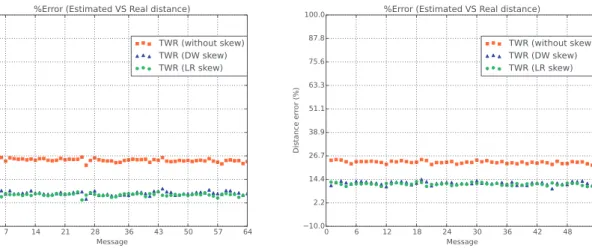
Fig. 17. Distance error: anechoic chamber
Table 3
Scenario’s configuration for ToF measurements.
Scenario Room Distance (meters)
Scenario 5 Anechoic chamber 2 Scenario 6 Anechoic chamber 3 Scenario 7 Non-isolated room 1 Scenario 8 Non-isolated room 2 Scenario 9 Non-isolated room 3
4.3.1. Scenarios
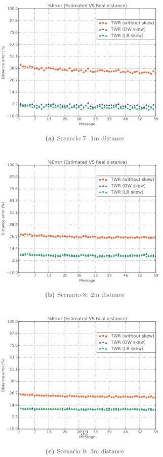
Scenarios were set upin two differentenvironments:an ane-choic chamber aswell asin a non-isolated room. Table 3 shows thescenarios’configuration.Here,Scenario5and6havethesame configuration parameters asScenarios’s 8and 9,respectively. We also included a fifth scenario in whichwe comparethe distance errorforadistanceofonemetre.Basedonthepreliminaryresults presentedinSection 4.2 ,antennaswerealignedinanoptimalway (angleof75° fornodeAand90° fornodeB).Forpracticalreasons, weconsiderthesecondscenario’sconfigurationwherebothnodes areinverticalposition.
Theidea thenistocompute theToFestimatedfromthe origi-nal TWR andtheSkew-Aware TWR(by means ofboth skew ap-proaches). Then, based on the computed ToF, the distance error (in percentageof the real distance) is derived. We consider two methods for estimatingthe skew: the linearregression approach ofSection 3.1 andtheDecaWave’sfunctionality.Wealsopresenta comparisonbetweenbothofthem.
4.3.2. Results
Figs. 17 and18 present theresultsintermsofthedistance er-ror computedfromtheToFestimationforeach ofthepredefined scenarios. Thesefigures show the percentageofthe realdistance that the errorrepresents. Thefirst conclusion we can drawfrom theseresultsis thatthe estimationoftheToF issignificantly im-proved when compensating itwiththe skewestimation. This re-sult was also confirmed in [26] fora skew estimated by means of the DecaWave’s functionality. Secondly,we can see that there is nosignificant difference between theestimation done by both skew compensationapproaches. This isdue tothe fact that both skewestimationsarenotsofarfromeachother.Fig. 19 showsthe skew’s evolution in partsper million (ppm) for both approaches. Green linerepresents theevolution ofthe computedslope while redpoints representtheestimatedskewfromDecaWaveDW1000 transceiver. As we can see, skew between nodes seems to
sta-bilise asthetimegoesby.Thismaybeduetothefact thatskew is affected by sensor’s temperature. In order to confirm this, we have run an experiment for 20 min in which we measure both skewandtemperatureforasetoftwonodesexchangingmessages.
Fig. 20 showsthat,after600seconds,bothtemperatureandskew stabilisesshowingthecloserelationshipbetweenbothparameters. In this experiment, node A sends one messageper second. After sendingthemessage,itturnstheradiooff inordertosaveenergy. On theother side, node Bremains awake inorderto receivethe message from A. This can explain the difference in terms ofthe temperaturebetweentwonodes.
Table 4 presentsthe average distance errorfor scenarios 5–9. The last two columns show that thedistance errorisalmost the same forboth skewestimationapproaches. However,a slight im-provement inthe ToFestimationcan be achievedwhen compen-satingtheskewbylinearregression(seeLRcolumn).
4.4. SDS-TWRandSkew-AwareTWRcomparison
Since SDS-TWR is conceived to minimise the impact of the clock skew, our objectivein thisexperiment set-up was to com-pareSDS-TWRwiththeSkew-AwareTWRintermsofthedistance error.Based onresultspresentedinprevious section(Fig. 19 ),we only consider the skew compensation based on linearregression since itisslightlymoreaccurate thantheDecaWave’s functional-ity.
4.4.1. Scenarios
Two scenarios were considered for this experiment, both of them were run in a non-isolated room fortwo distances: 2 and 3m.DetailsareshowninTable 5 .
4.4.2. Results
Fig. 21 showsdistanceerrorinpercentageofthe realdistance for both SDS-TWR and Skew-Aware TWR. SDS-TWR and Skew-Aware offer very close performance. However, as already high-lighted, SDS-TWR necessitates a nearly two-fold increase in the numberofmessagesexchanged.
Thisincrease,asshownlaterinSection 4.6 ,hasanegative im-pactonenergyconsumptioncomparedtoSkew-AwareTWR.
Table 6 shows the average distance error for both protocols. While SDS-TWR needs atleastfivemessages toachieve this pre-cision, ourapproachmakesonlyuseofthreemessages.Notethat thisnumbercanbereducedevenfurthertotwomessagesift2and
Fig. 18. Distance error comparison: non-isolated room
t3areembeddedintheACKmessage,asdonein[22] ,byusingthe
schedulingfunctionnalityofDW1000transceiver.
Finally, we have also carried out a t-test over the samples in ordertocomparethemeansofdistanceerrorsforbothapproaches. From Table 7 we can see that forboth scenarios, the p-value is belowthestandardthresholdsof0.05or0.01,sowerejectthenull
Fig. 19. DecaWave (DW) and Linear Regression (LR) skew evolution in parts per millon (ppm).
Table 4
Average error comparison between TWR (without skew), TWR (skew Linear Regression (LR)) and TWR (skew DecaWave (DW)).
Average error (meters)
Scenario Without skew Skew (LR) Skew (DW) Scenario 5 (ACH) 0.519 0.120 0.146 Scenario 6 (ACH) 0.7 0.357 0.372 Scenario 7 (NIR) 0.36 0.012 0.009 Scenario 8 (NIR) 0.534 0.145 0.158 Scenario 9 (NIR) 0.70 0.306 0.316 Table 5
Scenario’s configuration for SDS-TWR and TWR comparison.
Scenario Room Distance (meters)
Scenario 10 Non-isolated room 2 Scenario 11 Non-isolated room 3 Table 6
Distance error between SDS-TWR and TWR (with skew compensa- tion).
Average error (meters)
Scenario SDS-TWR TWR (LR skew)
Scenario 10 0.164 0.150
Scenario 11 0.343 0.328
Table 7
SDS-TWR and TWR (with skew compensation): t -test results. t -test over samples
Scenario t -statistic p -value
Scenario 10 7.335 1.319e-11
Scenario 11 10.194 1.288e-19
hypothesis andwe can say that thereis a statisticallysignificant differencebetweenbothmeans(Table 6 ).
4.5.LocalizationwithN-TWR
Previous experiments validate the quality of the Skew-Aware TWR approach defined in Section 3.1 . We have shown, for iso-lated and non-isolated environments, that the ranging precision achievedwithSkew-AwareTWRisinthesameorderthantheone achivedbySDS-TWR,butforareducednumberofmessages.Inthe followingexperiments,theperformanceofN-TWRisevaluatedfor thelocalizationofatargetnodebyN=3anchornodes.
4.5.1. Scenarios
Twoexperimentsare considered herefor2 differentlocations ofthetargetnode asdepictedon Fig. 22 .InSection 4.2 ,wehave
Fig. 20. Relationship between Temperature and Skew.
Fig. 21. SDS-TWR versus TWR with skew comparison.
Fig. 22. Scenario set-up.
shownthe importance ofaligning antennas inorder tominimise theToF estimationerror.Sincewe are consideringboth scenarios in 2D, it is impossible to perfectlyalign anchors’ antennas with the target node antenna. Inthe future,we expect torun our ex-perimentsby consideringomnidirectionalantennas(isotropic3D). The antennas configuration is done as follows: Anchors 2 and 3 are positioned at an angle of 45° with respect to the target an-tenna position. On the other hand, Anchor 1 is positioned at an angle of 180° with respect to the target antenna position. The
target node broadcasts a START message every 500 ms and, as showninFig. 8 (greenrectangles),anchorssendtheACKmessages following a schedulein order to avoidcollisions: Anchor 1 waits 400
µ
sbeforesendingitsACK,Anchor2waits800µ
sandAnchor 3 waits 1200µ
s afterthe arrival ofthebroadcast message com-ingfromthetargetnode.Atotalof536measurementsweredone. Regarding theconcentric circles, the setR of considered radii is definedasR={
r,r+k,r+2k,r+3k}
withk=10centimeters.For each measurement(
t1,t2i,t3i,t4i)
, the target node computes firstTable 8
Theoretic distances (cm) versus Estimated distances (cm), and ranging error (cm).
Anchor 1 Anchor 2 Anchor 3
N-TWR dth 1 (cm) Av.(d est(NTW R) 1 ) Error dth 2 Av.( d est(NTW R) 2 ) Error dth 3 Av.( d est(NTW R) 3 ) Error Scenario 12 100 93.79 6.21 141 133.14 7.86 141 114.47 26.53 Scenario 13 200 179.51 20.49 141 130.58 10.42 141 115.40 25.6
Anchor 1 Anchor 2 Anchor 3
SDS-TWR dth 1 Av.( d est(SDS) 1 ) Error dth 2 Av.( d est(SDS) 2 ) Error dth 3 Av.( d est(SDS) 3 ) Error Scenario 12 100 98.07 1.93 141 128.25 12.74 141 128.02 12.97 Scenario 13 200 184.02 15.97 141 130.34 10.65 141 127.05 13.94 Table 9
Average error between real and estimated target positions.
Scenario Error (cm) Standard deviation (cm) Best distance (cm) Worst distance (cm)
Scenario 12 10.32 1.77 6.08 16.47
Scenario 13 21.33 1.69 16.32 26.58
the ToF fromitself toeach of theanchors following N-TWR pro-tocol. Once the ToFs are estimated, the localization algorithm of
Section 3.2.2 isappliedtoestimatethelocationofthetargetnode.
4.5.2. Results
In thissection we present the resultsconcerning the protocol N-TWRandthequalityofthelocalizationofthetarget.The evalu-ationoftheN-TWRisdoneintwosteps:
• First, we comparethe ToFestimationof theN ranging opera-tion withN-TWR toa solutionwhereNconsecutiveSDS-TWR operationsareperformed.
• Second, we assessthe quality ofthe localizationofthe target nodewiththelocalizationalgorithmofSection 3.2.2 .
4.5.2.1. ToFwith N-TWRandSDS-TWR. The rangeobtainedwitha single N-TWRoperation andwith N SDS-TWR subsequent opera-tions is illustrated next. Letscall diest(NTWR) anddesti (SDS) the esti-mated distancesbetweenthetarget andanchoriforbothN-TWR andSDS-TWR,respectively.Sincebothtargetandanchorpositions are fixedandknown,thetheoreticdistancesare alsoknown.Lets calldth
i thetheoreticdistancebetweenthetargetandanchori.The
ranging error in centimeters is calculated with
|
diest(NTWR)−dth i|
.Table 8 lists the real and the estimated distance,as well asthe ranging error.SDS-TWR performsbetter forrangingwithanchors 1and3,whileN-TWRperformsbetterfortherangingwithanchor 2. Ranging operationsare in theorder oftens of centimeters for bothprotocols.
4.5.2.2. Localization error of the target. Once the target node has estimatedthedistancebetweenitselfandthesetofanchor,itwill be able to localise itself by means of the trilateration algorithm presented in Section 3.2.2 . Inthese experiments, the localization algorithmhasbeenexecutedoffline,onaregularcomputer.Fig. 23
showsthe estimatedtarget positionaftertheexecutionofthe N-TWRprotocolandthelocalizationalgorithm.Detailsareshownin
Table 9 in which we show theaverage error distance inmeters, thestandarddeviationaswellasthebestandworstdistanceerror. Werecallthatatotalof536measurementsweredone.Resultsare reallygoodastheaveragelocalizationerrorofthetargetisinthe rangeoftentotwentycentimeters.
4.6. Energyevaluation
Thissectionconcentratesontheenergyperformanceevaluation oftherangingprotocolsdiscussedinthispaper.Thismodelmostly offers a simplewayofcomparingthe energy consumptionofthe
Table 10
DecaWiNo energy consumption: MCU Freescale MK20DX256VLH7.
MCU state Details Power (Vcc = 3.3 V)
Active fCPU = 96 MHz 129 mW fCPU = 72 MHz 103 mW fCPU = 48 MHz 89 mW fCPU = 24 MHz 55 mW fCPU = 16 MHz 33 mW fCPU = 8 MHz 22 mW fCPU = 4 MHz 15 mW fCPU = 2 MHz 5,1 mW
Sleep Sleep, LPTMR wake 2 mW
Deepsleep, LPTMR wake 650 µW Hibernate, LPTMR wake < 30 µW Table 11
DecaWiNo energy consumption: Transceiver DecaWave DWM10 0 0 module.
State Details Power (Vcc = 3.3 V)
Active Transmit 145.8 mW
Receive 4 4 4 mW
Idle 39.7 mW
Sleep Sleep 0.029 mW
message exchange at the transceiver. Energy dissipation for pro-cessingmessagesbyCPUandcalculatingrangingdataisnot mod-eled herein. Moreover, to be consistent withour implementation oftheprotocolsonourMCU,we’rehavingtheCPUfunctioning in busy-waitingmode.Inotherwords,itcan’tgo intoa reduced en-ergyconsumptionstateduringemissionorreceptionofaframe.
Theprotocolsequences relyon severalMCUs2 (e.g.CPU,RAM,
flash)andtransceiver states.They all consumea different power leverasindicatedinTables 10 and11 .Thevalueslistedinboth ta-bleshavebeenverifiedonourtestbed.Theaimofthissectionisto calculatetheenergyconsumedbythetargetnodeforeach proto-col(TWR,SDS-TWR,2M-TWR,D-TWR,SDS-TWR-MAandour con-tribution N-TWR) and this when several anchors are considered. Theproposed derivation isbased ona classical modelwhere en-ergyisobtainedforeachstatebymultiplyingthepowerconsumed byastatebythetimethisstateisactiveintheprotocolsequence. FortheMCU,weconsidertwostates:active(withfCPU=48MHz)
and hibernate. For the transceiver, we consider all the available states.Tocomparetheprotocols,weconsiderasimpleenergy pro-fileforthetargetwithfourstates:
Fig. 23. Position estimation for each scenario.
• The action “sending message” has a duration Dtx where the
MCUisinactivemodeandthetransceiverintransmitmode.In thisfirstsimplemodel,wedonotconsiderframelength varia-tion:allmessageshavethesamelength.Thisactionimpliesan energeticalcostCtx,
• The action “wait-for-ack-frame” has a duration Drx−ack where theMCUisinactivemodeandthetransceiverinreceivemode. ThisactionimpliesanenergeticalcostCrx−ack,
• Theaction“wait-for-data-frame” hasa duration Drx−data where
theMCUisinactivemodeandthetransceiverinreceivemode. ThisactionimpliesanenergeticalcostCrx−data,
• Betweentheseactions,theremotenodeMCUisinactivemode andthetransceiverinidlemode,duringthecorresponding du-ration;thisimpliesenergeticalcostsCidle−ack andCidle−data.
The sequence diagrams of the investigated protocols are rep-resented inFig. 24 .In thisstudy,we compareall protocols using the samefollowing timing values: Dtx=200
µ
s; Drx−ack=400µ
s;Drx−data=800
µ
s. In reality of course, these timing values varyacross protocols. But thissimplifying assumption has been made tocomparetheprotocolonaunifiedbasis.Fromthesequence di-agrams, thetiming valuesof thefour statesandpowervalues of
Tables 10 and11 ,the energyconsumedbythe target nodewhen performinganN-aryrangingoperationtotheanchorsiscomputed foreachprotocol.
Fig. 25 represents,foreachprotocol,theenergycostofanN-ary ranging operationfora growingnumber ofanchorsinmillijoules (mJ). Aswe cansee,SDS-TWRandSDS-TWR-MAimplyahigh en-ergycostbecauseofthelongandrepeatedreceptionstates.N-TWR
Fig. 24. Ranging Protocols Sequence Diagrams. Blue rectangles represent reception states while red ones represente active transmission states. (For interpretation of the references to colour in this figure legend, the reader is referred to the web version of this article.)
Fig. 25. Energy Consumption at the target node when asking for an N-ary ranging for different protocols.
isthemostenergy-efficientprotocolsincetheanchorsaresolicited withasinglebroadcastmessage.
4.7. Resultsdiscussion
4.7.1. Skew-AwareTWRranging
In Section 4.3 ,we haveevaluated Skew-Aware TWRand com-paredwiththetraditionalTWRprotocol. Fromtheresultswecan
concludethatourapproachforcompensatingtheclock’sskew im-proves theperformance of theToF estimationwithout asking for any additional messageexchange between nodes.This is an im-portantimprovement tothe TWRprotocol toaccurately estimate theToF,andconsequently,therangingbetweennodes.Inorderto estimate the skew, two approacheswere proposed:the first one basedon a linearregressionestimation andthesecond one con-sideringthefunctionality ofDecaWave.Both approachesimprove theperformanceoftheToF’sestimation,asshowninFigs. 17 and
18 .However,resultsstemming fromthelinearregressionmethod are slightlybetter than the ones usingthe DecaWave’s function-ality.Besides,the linearregressionapproachcan beapplied inde-pendentlyoftheunderlyinghardware.
We have also compared our Skew-Aware TWR approach with SDS-TWR in terms of the distance error. Results in
Section 4.4 showthat ourapproachisslightlybetterthanthe es-timationprovidedbySDS-TWR.FurthermoreSDS-TWRrequiresat leastfivemessageexchangesforgettingranginginformationwhile Skew-AwareTWRneedsatmostthreemessages.Itcanbereduced to two messages to follow the emission scheduling capability of thehardwareasproposedinthe2M-TWRprotocol.
4.7.2. N-TWRProtocol
InordertoevaluateN-TWR,wehavecarriedoutanexperiment considering two scenarios by varying the distances betweenthe target node and one ofthe anchors. We have firstevaluated the
individualrangingerrorsbetweenthetargetandtheanchornodes bycomparingbothN-TWRandSDS-TWRprotocols.Sincepositions ofbothtargetandanchorsarefixedandknown,thetheoretic dis-tancesbetweenthem(dth
i )isknown.Thistheoreticdistanceisthen
comparedwiththeempiricalones(diest(NTWR)anddesti (SDS)). FromTable 8 wecanseethat,forthefirstscenario,theaverage distance error(considering the tree anchors)is about 13 cmfor theN-TWRwhilefortheSDS-TWR,9 cm.Forthesecondscenario, about18.8 cmforN-TWR and13.5forSDS-TWR.Forboth proto-cols, Table 8 suggeststhat thisdifferencebetweenboth scenarios maybeduetotheimpact ofthedistancebetweenthetarget and Anchor1,whichisdoubledfromonescenariotoanother.Thiscan be clearly seen when comparing d2est(NTWR) and dest3 (NTWR) (aver-age),whichremainalmostthesameforbothscenarios.Thesame canbeseenfortheSDS-TWRprotocol.
However,theaveragedistanceerrorfromthetargetnodeto An-chor 1 increases from6.21 to 20.49 cm for the case of N-TWR and from1.93 to 15.97 for SDS-TWR. Regarding the performance intermsofthedistanceerrorfortheN-TWRprotocolwithrespect to SDS-TWR,we canseethat SDS-TWR ismoreaccurate for esti-mating the distance betweenthe target node to each of the an-chors. However, SDS-TWR achievesan accurate estimation to the detrimentofthenumberofmessagesexchanges.Infact,SDS-TWR needs four messages between the target and a given anchor for estimatingtheToFandthus,twelvemessageswereneededinour experiments.Ingeneral,consideringNanchors,thetotalnumberof messageexchangesbetweentargetandanchorswouldbe4×N.On theotherhand,ourN-TWRprotocolneedsonlyN+1messagesfor achievinggoodresultswhicharenotsofarfromthoseobtainedby SDS-TWR.Themessagenumberreductionhasanimpactonenergy consumption, asseenon Fig. 25 : N-TWRisbetter than SDS-TWR sincetheanchorsaresollicitedwithasinglebroadcastmessage.
Asunderlinedpreviously,SDS-TWRoffersabetterrangingerror comparedtoN-TWR.Lookingcloserattherangingerrorstoanchor nodesin Table 8 ,we seethat thetheoretic distancebetweenthe target andanchors 2 and 3 is the same(141cm). Distances esti-mated withSDS-TWR are similarin both cases(around128 cm), whichisreasonable.However,withN-TWR,thedistanceestimated betweentargetandanchor2isofaround133cmandtheone be-tweentargetandanchor3ofaround114cm.Thisdifferencecanbe explainedbythefactthatthetimethat hasellapsedbetweenthe STARTmessageemissionandtheemissionoftheACKmessagesof anchors2and3isdifferent.Typically,theACKmessageofanchor 3 issent 400
µ
s after theone ofanchor 2.At the time the tar-get receives the last ACKof anchor 3, the timestamps measured fortheSTART messageemissionasrelevantanymoreasthe inter-nal clock drift ofthe anchor hasprobably changed.The best be-haviorofSDS-TWR isexplainedbythefactthatthetimeellapsed betweenSTARTandACKmessagesisshort.Thisresultcallforan implementationofN-TWRwherethenumberofanchorsstays lim-itedto3or4nodesmaximum.Even though the ranging error of N-TWR is a little larger the one of SDS-TWR, our localizationalgorithm ensures a ten to twenty localization accuracy of the target. Results presented in
Fig. 23 andinTable 9 clearlyunderlinethecomplementarityofthe N-aryrangingwiththelocalizationtrilaterationalgorithmwehave proposedherein.
Overall, we can concludeN-TWR is agood solution for track-ing a target node withan dozen centimeter-level accuracy in an indoorenvironment.Itoffersagreatlyreducedenergeticfootprint compared to the other solutions while achieving pretty accurate distanceestimations.Reducingthenumberofmessagesper local-izationoperationisbeneficial fortheoverallnetworkthroughput. Plusitoffersabettergroundforscalingthesystemtolocalize nu-meroustargetsconcurrently.
5. Conclusionsandfuturework
In this work we have presented N-TWR, a ToF-based N-ary ranging protocolforWSN in UWB.The aimof thisprotocolisto be abletoaccurately estimatethedistancebetweenatargetnode and a set of anchors. Therefore,we havefirst introduced an ap-proachforestimatingtheToFbetweentwonodes,takinginto ac-count theskew between nodeswhile minimizing the numberof exchangedmessages.Twotechniquesforestimatingtheskewwere presented,thefirstonebasedonaDecaWavefunctionalityandthe second one based on a linearregression approach, both ofthem efficiently improvingthe ToFprecision. Thesepreliminary results, together withthoseconcerningtheantennaalignment,were use-fulforconceivingaprotocol(N-TWR)whichisabletoestimatethe ranging betweennodeswhile minimizingtheimpact oftheskew aswellasthenumberofexchangedmessages.Wehavethen eval-uated theN-TWR protocol inLOS conditions,by comparing it to SDS-TWR,intermsofthedistanceerror.
Results in Section 4.5 show that the protocolachievesa good performance in terms of the distance error betweennodes even thoughresultsfromSDS-TWRareslightlymoreaccurate. Neverthe-less, SDS-TWR achievesa better performance tothe detrimentof the numberofexchanged messages whichinconsiderablyhigher compared to N-TWR. In fact, SDS-TWR needs 4×N messages to estimatethedistancebetweenthetargetandthesetofNanchors, while N-TWRonlyN+1.Therefore,wecan concludethat our N-aryrangingprotocolissuitableforapplicationsrequiringalimited numberofmessagesexchanged.N-TWRoffersthusareduced en-ergeticfootprintwhileachievingadozencentimeter-levelaccuracy forrangingoperations.
Finally, we haveproposed an improved localization algorithm that locatesatarget nodebyintersecting concentriccircles. Start-ing from the information regarding the distance between nodes (radius), a set of concentric circles are accounted for by varying theradius.The targetpositionisthencomputedby intersectinga setofcirclesandbystudyingdifferentcases.Resultsshowthatthe estimated target positionis intheorder aswell of10 to20 cm, whichisreallyencouraging.
Asafuturework,wewilltackletheproblemofscalingthe pro-posed solution. Therefore, we will work on a defining a higher layer protocol that will orchestrate the localization requests of multiple nodes.Tovalidate thiswork, we plan toextendour ex-periment setting: use more anchors (a deployment of 20 nodes is planned),longer distances(20 m),multipletargets. We aimas well at performing extensive measurements withrealistic indoor scenarios,includingNLOSconditions,WiFi/Bluetoothnetworks co-existence andmobilenodes.Tocarry outthisset ofexperiments, we plantouseomnidirectionalantennastoincreasetheprecision in the ToF estimation.Three rails, withthree mobile nodes with a millimeter positioning precision, will also be available on our testbedinthefuture;theywillenable theexecutionofautomatic positioning scenarios.We planaswellto workonafiner-grained energy consumption model by using more realistic state models thatincludesmessagelengthsandMCU/transceiversleepmodes.
Acknowledgments
ThisworkwassupportedinpartbytheFEDER/FrenchOccitanie Region withintheGUINNESSproject.
References
[1] G. Jekabsons, V. Kairish, V. Zuravlyov, An analysis of wi-fi based indoor positioning accuracy, Sci. J. Riga Tech. Univ. Comput. Sci. 44 (1) (2011), doi: 10.2478/v10143-011-0031-4 . http://www.degruyter.com/view/j/acss.2011. 44.issue- - 1/v10143- 011- 0031- 4/v10143- 011- 0031- 4.xml . .
[2] Y. S.-H. , T.A. Alhmiedat , A Zigbee-based mobile tracking system through wire- less sensor networks, Int. J. Adv. Mechatron. Syst. 1 (1) (2008) 63–70 .
![Fig. 4. D-TWR protocol [24] .](https://thumb-eu.123doks.com/thumbv2/123doknet/14333765.498463/6.892.56.430.391.1118/fig-d-twr-protocol.webp)