Publisher’s version / Version de l'éditeur:
Vous avez des questions? Nous pouvons vous aider. Pour communiquer directement avec un auteur, consultez la première page de la revue dans laquelle son article a été publié afin de trouver ses coordonnées. Si vous n’arrivez pas à les repérer, communiquez avec nous à [email protected].
Questions? Contact the NRC Publications Archive team at
[email protected]. If you wish to email the authors directly, please see the first page of the publication for their contact information.
https://publications-cnrc.canada.ca/fra/droits
L’accès à ce site Web et l’utilisation de son contenu sont assujettis aux conditions présentées dans le site
LISEZ CES CONDITIONS ATTENTIVEMENT AVANT D’UTILISER CE SITE WEB.
Proceedings of the 4th International Conference on Cold Regions Engineering,
pp. 751-759, 1986
READ THESE TERMS AND CONDITIONS CAREFULLY BEFORE USING THIS WEBSITE. https://nrc-publications.canada.ca/eng/copyright
NRC Publications Archive Record / Notice des Archives des publications du CNRC :
https://nrc-publications.canada.ca/eng/view/object/?id=da8a8773-2eab-41fd-979a-862c71c695b5
https://publications-cnrc.canada.ca/fra/voir/objet/?id=da8a8773-2eab-41fd-979a-862c71c695b5
NRC Publications Archive
Archives des publications du CNRC
This publication could be one of several versions: author’s original, accepted manuscript or the publisher’s version. / La version de cette publication peut être l’une des suivantes : la version prépublication de l’auteur, la version acceptée du manuscrit ou la version de l’éditeur.
Access and use of this website and the material on it are subject to the Terms and Conditions set forth at
Bearing capacity calculations for piles in permafrost
Ser
THl
National Research
Consell
nationel
N21d
Council
Canada
de
rec-
Canada
no.
1363
institute for
Imtitut de
c . 2
Research in
recherche en
BLrn
1
Construction
construction
Bearing Capacity Calculations
for Piles in Permafrost
by V.R. Parameswaran
ANALYZED
Reprinted from
Proceedin s of the 4th International Conference
Cold
8
egions Engineering, TCCqE, ASCE
Anchorage, AK, February 24-26,1986
p. 751 -759
(IRC Paper No. 1363)
Price $2.00
BLDG.
RES.
NRCC 25847
L I B R A R Y
ABSTRACT
S m a l l - s c a l e model p i l e s f r o z e n i n v a r i o u s s o i l s were t e s t e d a t c o n s t a n t r a t e s of d i s p l a c e m e n t and c o n s t a n t l o a d . The d e r i v e d v a l u e s were used t o c a l c u l a t e t h e naximurn a l l o w a b l e s t r e s s a t t h e p i l e - s o i l i n t e r f a c e .
- -
Des modsles r e d u i t s d e p i e u x p o s e s d a n s d i v e r s s o l s g e l & o n t 6 t 6 soumis
B
d e s e s s a i s 3 d e s v i t e s s e s d e dgplacement e t s o u s d e s c h a r g e s c o n s t a n t e s . On a u t i l i s g l e s v a l e u r s a i n s i Obten,,P.- - - -- - - I ---%-- -1- - u - * - - * a * - a d m i s s i b l e 3Reprinted from Proceedings o f the 4th Int7. Conference Cold Regions Engineering, TCCRE, ASCE
Anchorage, A K , February 24-26.1986
BEARING CAPACITY CALCULATIONS FOR PILES IN PERMAFROST V. R. Parameswaran*
Small-scale model piles frozen in various soils were tested at constant rates of displacement and constant load. The derived values were used to calculate the maximum allowable stress at the pile-soil interface based on: 1) minimum or steady-state displacement rates observed in the constant-load creep tests, and 2) time to failure, which is equal to the time to attain peak load in tests carried out under constant dis9lacement rate and (for constant-load creep tests)
time to the onset of tertiary OL accelerating creep. The latter
method, which applies Vyalov's equation to constant-load creep tests, gives the lowest value for allowable stress, based on a failure time of 25 years, and can provide a better margin of safety during the life of a structure founded in permafrost.
Introduction
Pile foundations are probably the simplest and most commonly used support for structures built in permafrost areas. They bear the load of the structure by means of two mechanisms: adfreezing strength between pile and soil, and end bearing. The total bearing capacity of a pile embedded in frozen ground can be calculated by suitably
combining the contributions of the two mechanisms. The effect of the active layer, which seasonally freezes and thaws, is usually ignored since the pile is embedded in the perennially frozen ground to a depth great enough to overcome the effects of heaving and slumping. In the early days of construction it was common practice to embed the pile at a depth below the permafrost table at least three times the thickness of the active layer.
An empirical formula can be used to calculate the total bearing capacity of a pile (Vyalov and Porkhaev, 1976):
where rd: is the adfreeze strength in the ith layer in ground
consisting of n layers, Ai is the adfreezing area between pile and
soil in that layer, o is the compressive strength of the soil under
the tip of the pile, and Ab is the end-bearing area of the pile. In most soils the coefficients of homogeneity, k l and k p , can be assumed
"Research Officer, Division of Building Research, National Research Council of Canada, Ottawa, Canada. KIA OR6
752 COLD REGIONS ENGINEERING
to be equal to 1. For reticulate or layered ice-rich soils with a fractional ice content. i, k, = 1-i. The coefficients of performance, ml, and m
,
are equal to 1 for most soils for temperatures below -2OC. For most $ine-grained clayey soils m2 I 1 to 1.5. For coarse-grained soils, however, ma takes values of up to 2.5; and for piles resting on an ice layer or piles placed in steamed or slurried holes, m2 = 0.If end-bearing is neglected and it is assumed that the ground consists mostly of one type of soil, considered to be homogeneous, the equation reduces to:
where Tad is average adfreeze strength between pile and frozen soil, and A is the total interfacial area.
Thus the important parameter that governs bearing capacity is T,
and the objective of any good design is to provide a value for allowable stress, that can be borne by the pile foundation without exceeding the total allowable settlement during the life of the structure. T~ will depend on temperature, grain size, and moisture content of the soil and the characteristics of the pile Itself. The soil at the pile-soil interface is under a constant load, and therefore the creep characteristics of the soil must be known.
As sufficient data regarding adfreeze strength do not exist for all soils and terrains. the range of long-term adfreeze strength values for given soils has to be determined from short-term tests carried out in.the laboratory (using model piles), or the field (using full-scale piles) or from long-term tests of piles under constant load. As discussed in an earlier paper (Parameswaran 1985), there are
essentially three methods of estimating the allowable stress, T ~at ~ ~ , the pile-soil interface from such tests.
1) The peak adfreeze strength determined from constant-rate tests is plotted against the imposed rate of displacement (usually on a log-log or semilogarithmic scale) and the resulting curve extrapolated
backwards to the allowable displacement rate. A total allowable settlement of 1 in. (25.4 mm) in 25 years, for example, will correspond to an allowable average rate of settlement of about
2 x mm/min. The value of T~~~ SO obtained, however, is an upperbound value, and large factors of safety may have to be used in design calculations.
2) The minimum displacement rates observed in the constant-load creep tests are plotted against corresponding stresses to give the value of allowable stress corresponding to allowable displacement rate. The assumption in this procedure is that the transient creep regime (consisting of instantaneous displacement as well as primary or attenuating creep) is negligibly small compared with the steady-state creep regime. This is not a valid assumption in most instances. The method does, however, give a smaller value for allowable stress than that obtained from the short-term tests carried out under constant displacement rates,
PILES IN PERMAFROST 753
3) The third method makes use of an equation relating time, tf, for
the onset of tertiary or accelerating creep and applied stress, T.
Analogous to many viscoelastic materials, for frozen soils this relation is given by:
where to and T~ are constants characteristic of the material and have
dimensions of time and stress, respectively. The equation was first suggested by Vyalov (1959, 1962) and has been used extensively (Sayles, 1968, 1973; Sayles and Haines, 1974) for various frozen soils. The term tf is called failure time.
Thus, by plotting In (tf) as a function of stress for various pile tests at different temperatures the values of the constants to
and T~ can be determined. For a particular failure time, tf, the
allowable stress can be obtained from the plot or by calculation. This method takes into account the transient creep regime and the secondary or steady-state region of creep, i.e., the total creep curve from the beginning of a test until the onset of tertiary or
accelerating creep.
This paper assesses the three methods by applying them to data obtained from pile tests carried out in the laboratory on frozen soils under controlled conditions.
I
Experimental ProcedureI
! Small-scale model piles (diameter 3 in.; 76.2 mm) made from
natural wood (B.C. fir or spruce), steel, and concrete were frozen
I into three soils: sand of uniform grain size containing 14% moisture
'
by weight and compacted to an optimum Proctor dry density, yd, of
1700 kg/m3; silty sandy soil from N.W.T. containing 20% moisture; and
silty clay from N.W.T. containing 45% moisture by weight. The piles
were tested under constant displacement rates and under constant-load
' creep conditions in a cold room maintained at a temperature of -6OC.
The constant-rate tests were carried out on a screwaperated universal. testing machine of 25-ton (250 kN) capacity; the constant-load tests were carried out on a creep frame designed and built for the purpose. Details as to grain size of the soils, compaction, experimental set-up, etc., have been described (Parameswaran, 1978, 1979). Discussion
I To illustrate the different methods of estimating the allowable
stress on piles, i.e., that at which allowable settlement (for
convenience a value of 1 in. (25.4 mm) in 25 years (1.314 x
lo7
min)is considered for calculations) and rate of settlement
r (1.933 x mmlmin) are not exceeded, the data obtained in only one
soil (frozen fine-grained sand) are considered. Rate-controlled tests
754 COLD REGIONS ENGINEERING
peak adfreeze strength, rf, for p?les embedded in frozen sand is related to rate of displacement, L, by a power law equation:
with values of the exponent n ranging between 4.5 and 6 for wood, concrete, and painted steel, and equal to 10 for uncoated steel. For a pile displacement rate of 2 x mm/min (corresponding to a total settlement of 1 in. in 25 years), the cross-head displacement rate is
8
x mm/min; the actual rate of displacement of the pile withrespect to the soil was always smaller than the set rate owing to the elasticity of the machine (Parameswaran, 1981). The corresponding peak adfreeze strength values ate (Parameawaran, 1978): 0.65 MPa for
B,C. fir, 0.57 MPa for spruce, 0.25 MPa for piles with a smooth surface (such as concrete, painted steel, and creosoted B.C. fir), and
0.38 MPa for uncoated steel.
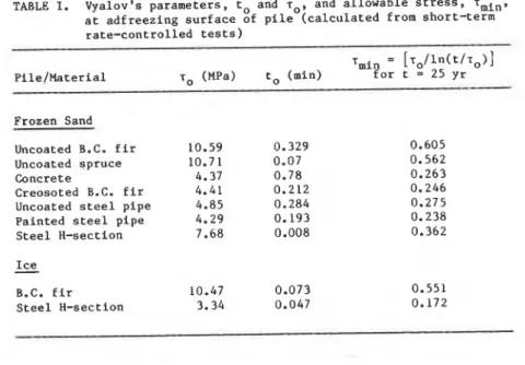
The data from these tests were also fitted to Equation (3) relating ln(t), where t is the time to attain peak adfreeze strength and the inverse of the stress at the pile-soil interface. Figure 1 shows such a plot for various piles in frozen sand. The values of the characteristic constants, to and T ~ , and the values of the allowable stress for a life of 25 years (t = 1.314 x
lo7
min) calculated from these curves are shown in Table 1. For most of the piles the value of T so obtained is slightly smaller than that determined byextrapolating the results from rate-controlled tests.
TABLE I. Vyalov's parameters, to and lo, and allowable stress, lmin, at adfreezing surface of pile (calculated from short-term rate-controlled tests)
lmin = [~~/ln(t/~~)]
lo (MPa) to (mid for t = 25 yr
Frozen Sand
Uncoated B.C. fir 10.59
Uncoated spruce 10.71
Concrete 4.37
Creosoted B.C. fir 4.41
Uncoated steel pipe 4.85
Painted steel pipe 4.29
Steel H-section 7.68
Ice
-
B.C. fir 10.47
PILES IN PERMAFROST 3 . 0
, ,
,,,,,,,,
I,
l r r r l l r,
-
m---* CREOSOTED 0. C. F I R I- 2 . 5 -,
,
---
-o CONCRETE (D-
L 0- SPRUCE 2 . 0-
om.- B.C. F I Rz
1 . 5 - az-
*
1 . 0-
1 10 100 1 000 10 000 T l M E TO F A I L U R E , t,, m i n 3 . 0,
I,
IT.,,,,
1 1 1 1 1 1 1,
1 1 1 1 1 1-
.---.
PA l NTED STEEL CY LlNDER '- 2 . 5 - ...m v UNCOATED STEEL CYLINDER
a A-...-A STEEL H-SECTION / / H ~ -
=
2 . 0 -...
&..#....-+ VI@/:--
....
:v-...
v....--"',
-.:
z
1 . 5-
-
E C 1 . 0-
-
... Y r 4-
0'
1 " " ' 1'
""ill'
I l l ' l l L a a 1 1 ' 1 ' 1 10 100 1 000 10 000 T l M E TO F A I L U R E , t,, m i nFigure 1 Variation of time-to-failure, tf, with (stress)-l, from
I short-term rate-controlled tests o n piles in frozen sand
at - 6 O C . (a) Results for wood and concrete piles (b) Results for steel piles
756 COLD REGIONS ENGINEERING
Constant-load creep tests
The results of the rate-controlled tests will be compared with the results from long-term creep tests of piles in various soils. Some have already been reported (Parameswaran, 1979, 1980). In view of the different stages of creep before ultimate failure, no simple relation giving a failure life in terms of common test parameters can be given that will have universal application. Simple relations have been used, however, to predict the life under a given stress or the limiting or allowable stress for a given life span. The steady-state creep rate, f, can be related to the applied stress, 7, by a power law similar to Equation (4). with the exponent, n, equal to 8.1 for uncoated wood, 9.1 for concrete, and 6.7 for painted steel
(Parameswaran, 1979). Johnston and Ladanyi (1972, 1974) also reported values of n equal to 7.5 and 8.05 from field data obtained from pile pullout tests conducted in permafrost areas in Thompson and Gillam, Manitoba.
From a plot of displacement rate versus applied stress from constant-load creep tests the allowable stress at the pile-soil
interface for a displacement rate of 2 x mm/min was found to be
0.37 MPa for wood and steel piles in frozen sand at -6'C, and 0.22 MPa for concrete (Parameswaran, 1980). These values are much smaller than those calculated from the rate-controlled tests.
The data from the long-term creep tests were also fitted to Equation (3), with tf equal to the time for the onset of accelerating or tertiary creep. Figure 2 shows the variation of failure time; tf, with applied stress, r , for wood and steel piles in different soils. Consider line AA, the least-squares fit through the various points: the values of T and to calculated from the slope of this line were 2.792 MPa and 23.10 min, respectively, and the value of T~~~ for a 25-year life for these piles in frozen sand, silt, and clay was calculated to be 0.21 MPa. If line BB is considered as an upper bound for l/r or a lower bound for the allowable stress for wood piles in frozen clay, however, the value of T,,,.~ for a 25year life is again 0.21 MPa. This value for T~~~ is muck smaller than the values calculated by other methods. Values of the limiting or allowable stress, T
.
,
for an uncoated B.C. fir pile in frozen sand at -6OC. calculate8'Ey various methods and based on an estimated life of 25 years, are as follows:#
T~~~ (MPa)
Extrapolated from fast, rate-controlled tests: 0.65
Vyalov's method (Equation 3) applied to fast tests: 0.60
From minimum or steady-state creep rates: 0.37
Vyalov's method (Equation 3) applied to
PILES IN PERMAFROST 757
Comments on Vyalov's method
Comparison of the values quoted above shows that Vyalov's method of using failure time, when applied to short-term rate-controlled tests, gives much higher values of allowable stress than those corresponding to the minimum creep rates observed from the
steady-state region in constant-load creep tests. When applied to data from creep tests, however, the method gives a smaller value of allowable stress for long-term bearing-capacity calculations.
When Vyalov's method is applied to short-term tests, it gives in some instances values of allowable stress even larger than those obtained from extrapolation of data from short-term tests. For example, from short-term rate-controlled tests carried out on piles frozen in freshsrater ice, the extrapolated values of adfreeze stress
for a rate of 2 x mm/min were 0.42 MPa for wood piles, and
0.12 MPa for steel piles (Parameswaran, 1981). Figure 3 shows the
same results replotted as In (tf) versus 11~. The values of allowable
stress calculated using a failure time, tf
,
of 1.314 x lo7 min(25 years) were 0.551 MPa and 0.172 MPa, respectively, for wood and steel piles embedded in ice. These values are larger than the extrapolated values from short-term tests, showing that Vyalov's method does not necessarily give better results than plain
extrapolation when applied to short-term, rate-controlled tests. It is, however, a convenient method to use with data from constant-load creep tests for estimating long-term bearing capacities of piles in permafrost. T
-
S A N D S I L T C L A Y-
-
WOOD 0 A 0-
-
S T E E L A-
-
-
-
-
-
-
-
,--D---,- B ---.-u-- +-
A A 0-3-
u A 0 A-
-
I T I M E TO F A I L U R E , tt, m i n!
,
Figure 2 Variation of time-to-failure, tf,
with (stress)-l, fromCOLD
REGIONS ENGINEERING o B . C . F I RFL:
C O N C R E T E a S T E E L A 0 1'
'
1 1 1 1 1 1 a 1 1 1 1 1 1 I l l l 1 l 1o1
1o2
l o 3 1o4
TIME TO F A I L U R E , t f , m i nFigure 3 Variation of time-to-failure, tf, with (stress)-l, from rate controlled tests on piles frozen in ice at -6*C
Conclusion
Results of short-term, rate-controlled tests and longer-term, constant-load creep tests reveal that the lowest value of allowable stress at the pile-soil interface is obtained from creep tests that consider time to failure. This is the total time to the end of the steady-state regime prior to the onset of tertiary or accelerating creep. This method, suggested by Vyalov for frozen soils, yields the lowest values of allowable stress at the pile-soil interface, and is thus a safe, although conservative, estimate of the long-term bearing capacity of piles in permafrost.
Acknowledgement
This paper is a contribution from the Division of Building Research, National Research Council of Canada.
Appendix
-
ReferencesJohnston, G.H. and Ladanyi, B. 1972. Field tests of grouted rod anchors in permafrost. Canadian Geotechnical Journal, Vol. 9, pp. 176-194.
Johnston, G.H. and Ladanyi, B. 1974. Field tests of deep power installed screw anchors in permafrost. Canadian Geotechnical Journal, Vol. 11, pp. 348-358.
PILES IN PERMAFROST
Parameswaran, V.R. 1978. Adfreeze strength of frozen sand to model
piles. Canadian Geotechnical Journal, Vol. 15, pp. 494-500.
Parameswaran, V.R. 1979. Creep of model piles in frozen soils.
Canadian Geotechnical Journal, Vol. 16, pp. 69-77.
Parameswaran, V.R. 1980. Adfreeze strength and creep of frozen soils
measured by model pile tests. Proceedings, Second International Symposium on Ground Freezing, Trondheim, Norway, pp. 157-164.
Parameswaran, V.R. 1981. Adfreeze strength of model piles in ice.
Canadian Geotechnical Journal, Vol. 18, pp. 8-16.
Parameswaran, V.R. 1985. Attenuating creep of piles in frozen soils.
Proceedings, Foundations in Permafrost and Seasonal Frost. ASCE Spring Convention, Denver, Colorado, pp. 16-28.
Sayles, F.H. 1968. Creep of frozen sands. U.S. Army Cold Regions
Research and Engineering Laboratory (CRREL), Technical Report 190, 54 p.
Sayles, F.H. 1973. Triaxial and creep tests on frozen Ottawa sand.
Proceedings, Second International Conference on Permafrost,
Yakutsk, U.S.S.R. North American Contribution, National Academy
of Sciences, Washington, D.C., pp. 384-391.
Sayles, F.H. and Haines, D. 1974. Creep of frozen silt and clay. U.S. Army Cold Regions Research Engineering Laboratory, (CRREL), Technical Note 252, 54 p.
Vyalov, S.S. 1959. Rheological properties and bearing capacity of
frozen soils. (Izdatel'stvo Akademii Nauk SSSR, Moscow). U.S. Army Cold Regions Research and Engineering Laboratory (CRREL), Translation No. 74 (1965), 219 p.
Vyalov, S.S. and Porkhaev, G.V. (ed) 1976. Handbook for the design of bases and foundations of buildings and other structures on permafrost. (Izdatel'stvo Literary po Stroitel'stvu, Mscow,
1969, 129 p.). National Research Council of Canada, Technical
Translation 1865 (1976).
Vyalov, S.S. (ed) 1962. The strength and creep of frozen soils and calculations for ice-soil retaining structures. (Izdatel'stvo
Academia Nauk SSSR, Moscow). U.S. Army Cold Regions Research
Engineering Laboratory (CRREL), Translation No. 76 (1965), 301 p.
T h i s p a p e r i s b e i n g d i s t r i b u t e d i n r e p r i n t f o r m by t h e I n s t i t u t e f o r R e s e a r c h i n C o n s t r u c t i o n . A l i s t of b u i l d i n g p r a c t i c e a n d r e s e a r c h p u b l i c a t i o n s a v a i l a b l e f r o m t h e I n s t i t u t e may b e o b t a i n e d by w r i t i n g t o t h e P u b l i c a t i o n s S e c t i o n , I n s t i t u t e f o r R e s e a r c h i n C o n s t ~ c t i o n , N a t i o n a l R e s e a r c h C o u n c i l o f C a n a d a , O t t a w a , O n t a r i o , K I A 0R6. Ce document e s t d i s t r i b u e s o u s forme d e t i r e - 3 - p a r t p a r l l I n s t i t u t de r e c h e r c h e e n c o n s t r u c t i o n . On p e u t o b t e n i r u n e l i s t e d e s p u b l i c a t i o n s d e 1 ' I n s t i t u t p o r t a n t s u r les t e c h n i q u e s ou l e s r e c h e r c h e s e n