Biphasic Electrode Suspensions for Li-Ion
Semi-solid Flow Cells with High Energy Density, Fast
Charge Transport, and Low-Dissipation Flow
The MIT Faculty has made this article openly available. Please share how this access benefits you. Your story matters.Citation Wei, Teng-Sing, Frank Y. Fan, Ahmed Helal, Kyle C. Smith, Gareth
H. McKinley, Yet-Ming Chiang, and Jennifer A. Lewis. “Biphasic Electrode Suspensions for Li-Ion Semi-Solid Flow Cells with High Energy Density, Fast Charge Transport, and Low-Dissipation Flow.” Advanced Energy Materials 5, no. 15 (June 5, 2015): 1500535.
As Published http://dx.doi.org/10.1002/aenm.201500535
Publisher Wiley Blackwell
Version Author's final manuscript
Citable link http://hdl.handle.net/1721.1/107821
Terms of Use Creative Commons Attribution-Noncommercial-Share Alike
DOI: 10.1002/((please add manuscript number)) Article type: Communication
Biphasic Electrode Suspensions for Li-Ion Semi-Solid Flow Cells with High
Energy Density, Fast Charge Transport, and Low-Dissipation Flow
Teng-Sing Wei, Frank Y. Fan, Ahmed Helal, Kyle C. Smith*, Gareth H. McKinley*, Yet-Ming Chiang*, and Jennifer A. Lewis*
Prof. J. A. Lewis, T. S. Wei
School of Engineering and Applied Science Harvard University
Cambridge, MA 02138 (USA) E-mail: jalewis@seas.harvard.edu Prof. Y. M. Chiang, F. Y. Fan
Department of Materials Science and Engineering Massachusetts Institute of Technology
Cambridge, MA 02139 (USA) E-mail: ychiang@mit.edu Prof. G. H. Mckinley, A. Helal
Department of Mechanical Engineering Massachusetts Institute of Technology Cambridge, MA 02139 (USA)
E-mail: gareth@mit.edu Prof. K. C. Smith
Department of Mechanical Science and Engineering University of Illinois at Urbana-Champaign
Urbana, IL 61801 (USA) E-mail: kcsmith@illinois.edu
Keywords: flow battery, lithium ion, colloidal suspension, rheology, conductivity
The rapidly increasing deployment of wind and solar energy has resulted in an urgent need for a smarter, more efficient and reliable electronic grid for load balancing.[1,2] Currently, only a small fraction of the total electric production is tied to grid storage, with the vast majority
being pumped hydro installations.[3] While the latter technology is mature, cost effective, and efficient, it is geographically limited.[3] Alternate modes of energy storage that can be deployed in a distributed manner include batteries, compressed air, thermochemical energy, and flywheels.[3]
Flow batteries are particularly attractive due to their decoupled energy and power, providing design flexibility especially at large scales.[4-6] Many flow battery chemistries, however, suffer from limited complex solubility and low nominal voltage, resulting in low energy densities.[7] To overcome this, Duduta et al. developed the semi-solid flow cell (SSFC),[8] in which traditional liquid catholytes and anolytes are replaced by attractive colloidal suspensions composed of Li-ion compounds. They also replaced traditional stationary current collectors with conductive carbon nanoparticle networks within the flowing suspensions. These suspensions, which take advantage of Li-ion battery’s high energy density with flow battery’s design flexibility, have been investigated both experimentally[8-12] and computationally.[10,13,14] Similar concepts have recently emerged for electrochemical flow capacitors[15] and polysulfide flow batteries.[16]
To fully optimize SSFCs, the flowing electrodes must have high active material content coupled with an adequate conductive filler network to overcome the resistive nature of most electrochemically active Li-ion compounds. However, as their solids loading increases, dramatic changes in their rheological properties ensue, which inhibit flow. The key to maximizing active material content while retaining satisfactory flowability and conductivity is to simultaneously tailor the respective interactions between all particles present within these electrode suspensions.[17]
Here, we report the design and characterization of biphasic SSFC electrode suspensions with high energy density, fast charge transport, and low-dissipation flow. To create these biphasic mixtures[18,19] we specifically tailor the interactions between the active particles, i.e., LiFePO4 (LFP), to be repulsive, the interactions between the conductive particles, Ketjenblack EC-600JD (KB), to be attractive, and the cross-interactions between LFP-KB to also be repulsive. These two particle populations are suspended and mixed sequentially in propylene carbonate (PC) with 1M of lithium bis(trifluoromethane)sulfonamide (LiTFSI). It is well known that colloidal particles will rapidly aggregate when suspended in polar solvents under high ionic strength conditions due to van der Waals interactions.[20] Hence, we first introduce a non-ionic dispersant, polyvinylpyrrolidone (PVP), with appropriate amount to selectively stabilize the LFP particles fully, but not the KB particles.[21-23] PVP has been shown to sterically stabilize colloidal particles in both aqueous[22-24] and non-aqueous[25] media leading to well dispersed suspensions. PVP is especially useful for SSFC electrodes, as it confers stability even in systems with high (1 M) salt concentrations that undergo electrochemical charging and discharging. We chose LFP due to its low volume expansion (εlinear ∼ 2.2%)
[24] when charged or discharged.
We then added Ketjenblack EC-600JD (KB) particles to the suspension, which form a conductive network at a low percolation threshold.[25] We investigated the effects of biphasic suspension composition on the microstructure, flow behavior, and electrochemical performance of these SSFC electrodes. We show that well-dispersed (repulsive) LFP particles, surrounded by a percolating (attractive) KB network, enable quick and efficient charge transport that reduces overpotential during cell cycling. For comparison, we also created purely attractive LFP-KB suspensions in the absence of PVP and investigate their performance. Finally, we developed an
analytical model that predicts the pressure drop needed for a given target current, based on these measured properties.
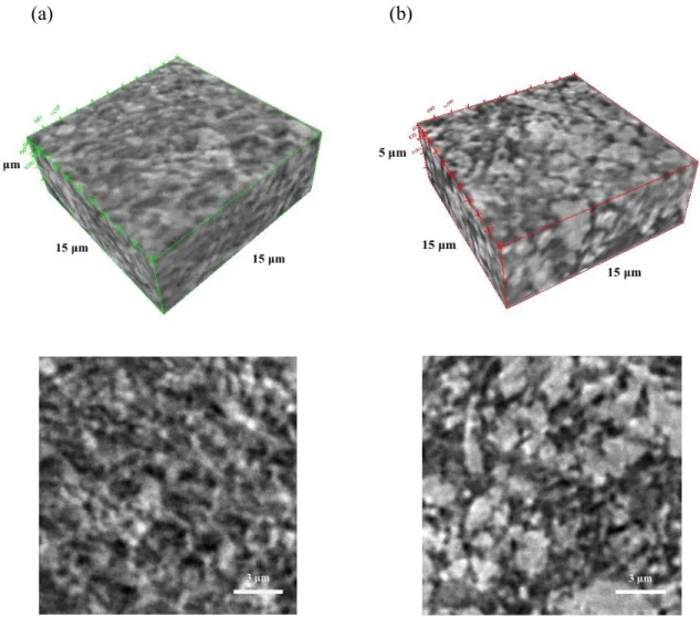
We first characterized the microstructure of both biphasic and purely attractive LFP electrode suspensions using nanoscale-computed tomography (nano-CT). The 3D reconstructed images and 2D slices of both systems are provided in Figure 1. Their respective compositions are 20LFP/1.25KB/0.3PVP and 20LFP/1.25KB/0PVP, where the numbers denote the volume percent of LFP and KB particles and weight percent of PVP (in solution) in each suspension. The biphasic mixtures, which contain PVP-stabilized LFP particles are clearly more homogeneous than their purely attractive counterparts that do not contain PVP. These observations are in excellent agreement with prior findings, in which the presence of a repulsive particle population within model biphasic mixtures led to a more homogeneous attractive particle network composed of smaller clusters and voids.[18,19]
To explore dispersant effects on flow behavior, we carried out both shear viscometry and oscillatory measurements on biphasic and purely attractive LFP electrode suspensions with the same compositions described above. Their measured flow curves and shear elastic and loss moduli are shown in Figure 2a-b, respectively. Concentrated colloidal suspensions are prone to wall slip effects during measurements.[26-29] Here the flow curves for biphasic LFP suspensions are slip-corrected[26] and exhibit nearly identical behavior over multiple gap heights (Figure S1). The inhomogeneity of the purely attractive electrode suspensions makes slip correction difficult. Their flow curve, which represents a lower bound, is acquired at the gap height of 0.8 mm. Both the biphasic and purely attractive suspensions exhibit a shearing thinning response (Figure S2) and a shear yield stress (Figure 2a). However, the apparent viscosity of the biphasic system is nearly an order of magnitude lower than its purely attractive counterpart at a given shear rate.
The same trend is observed for shear yield stress, which is an order of magnitude lower for the biphasic LFP suspension. Fits to the Herschel-Bulkley model[30] are shown in Figure 3a and regression to the experimental data gives an extrapolated yield stress of 661 Pa and 5,488 Pa for the biphasic and purely attractive LFP suspensions, respectively.
The corresponding viscoelastic storage (G!) and loss moduli (G!!) are provided in Figure
2b for the same biphasic and purely attractive LFP electrode suspensions. We find that both suspensions behave predominantly as elastic solids
(
G >> !!! G)
, indicating percolated network of particles exist within each system. However, once again, we find that the biphasic suspensions exhibit an order of magnitude lower stiffness (0.145 MPa) than the purely attractive counterparts (2.46 MPa). We note that the design of electrolyte suspensions that exhibit a shear thinning response, a shear yield stress, and viscoelastic behavior is advantageous for SSFC applications, because it reduces particle sedimentation, phase segregation, and unwanted mixing of charged and discharged regions.This strategy can be readily applied to other active materials, such as lithium titanate (LTO). To demonstrate this, we created both biphasic and purely attractive LTO electrode suspensions with compositions of 20LTO/1.5KB/0.3PVP and 20LTO/1.5KB/0PVP, respectively. The slip-corrected flow curves for the biphasic LTO suspension (Figure S1) also exhibit nearly identical behavior over multiple gap heights. Both LTO suspensions exhibit a shear thinning response (Figure S2), a shear yield stress and viscoelastic behavior (Figure S3). Their measured flow curves and viscoelastic moduli are shown in and, respectively. However, akin to the biphasic LFP suspensions, the apparent viscosity (at a given shear rate), shear yield stress and shear elastic modulus of the biphasic LTO suspensions are nearly an order of magnitude lower than their purely attractive counterparts. For example, Herschel-Bulkley fits give extrapolated
shear yield stress values of 355 Pa and 4,085 Pa for the biphasic and purely attractive LTO suspensions, respectively.
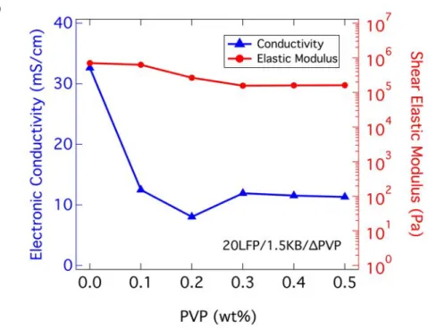
To broadly explore the effects of suspension composition, we carried out electronic conductivity and oscillatory measurements on biphasic electrode suspensions of varying LFP, KB, and PVP content (Figure 3). We first characterized biphasic suspensions with varying KB vol% composed of LFP (20 vol%) and PVP (0.3 wt%). We consistently observed a positive correlation between their electronic conductivity, shear elastic modulus, and KB content. Even at the lowest KB content (1 vol%) explored, these particles form a percolating network that gives rise to a measurable electronic conductivity and shear elastic modulus. However, upon increasing to 2 vol% KB, there is a power law growth in both electronic conductivity and shear elastic modulus (Figure 3a), indicating that that the interparticle bonds within this percolating particle network has dramatically increased. Next, we fixed the KB (1.5 vol%) and PVP (0.3 wt%) contents and explored the effects of LFP (from 0 vol% to 25 vol%) on the electronic conductivity and shear elastic modulus of these biphasic electrode suspensions (Figure 3b). As observed in Figure 1 and S1 as well as reported previously for model biphasic suspensions, the presence of repulsive LFP particles alters both the long-range and local structure of the attractive KB network. In the absence of LFP particle, the attractive KB particle network consists of large, dense clusters that surround open regions filled with solvent and salt species. Upon adding repulsive LFP particles, the attractive KB particle network becomes more homogenous, favoring the formation of more tenuous, linear chains with fewer bonds between KB particles. The repulsive particles have significantly slower mobility than solvent molecules or ionic species. When randomly distributed amongst a population of attractive particles, these species can frustrate the formation of attractive particle bonds thereby yielding aggregated systems that are
kinetically trapped in a more structurally uniform state.[18,19] The concomitant rise in both electronic conductivity and shear elastic modulus with increasing LFP content reflects this microstructural evolution within these biphasic suspensions (Figure 3b). Simply put, as the conductive network becomes more homogeneous at a fixed number density of attractive KP particles, there are more pathways for transporting electronic current within the electrode suspensions and the shear elastic modulus increases. We note that in the absence of attractive KB particles, the shear elastic modulus is indeed quite small (1.2 Pa), indicative of a structure-less liquid state expected for well-dispersed LFP suspension (20 vol% LFP, 0.3 wt% PVP). Finally, we fixed both the LFP (20 vol%) and KB (1.5 vol%) contents and varied the amount of PVP from 0 to 0.5 wt% to determine its effects on performance. Results show that once a critical amount of PVP (0.3 wt%) is introduced to the suspension to stabilize the particles, both electronic conductivity and shear elastic modulus vary minimally with further addition of PVP (Figure 3c). The above data reveal that optimizing biphasic electrode suspensions for use in semi-solid flow cell batteries is not straightforward. Both their ability to charge/discharge efficiently and flow readily through the flow cell is important. These criteria are often in tension, since the carbon black (KB) network gives rise to both the desired electronic conductivity (which facilitates charge transfer) and a yield stress (which increases pumping pressure). [25,31]
To identify the suitable SSFC suspension composition, we developed an electrode-scale model that incorporates efficiency and flowability criteria. For all suspensions, the modeled cell is subjected to a current density i of 10 mA cm-2 with a current-collector length Lcc of 20 mm.
For each suspension, the cell is designed with an electrode thickness w that produces a voltage efficiency ηV of 90%, where ηV is defined as:
where φeq is the average open-circuit voltage of the cell, and ΔΦ is the average polarization.
We assume that the electrochemical reactions propagate via a planar front through the electrode’s thickness, producing an average polarization that decreases as the effective electronic conductivity σeff and effective ionic conductivity κeff increase:
ΔΦ = iw
(
κeff +σeff)
(
2κeffσeff)
(2)This trend is shown in Figure 4a for suspensions with various loading levels of LFP.
The model couples charge-transfer and rheology properties by accounting for the high flow velocities required to cycle thin electrodes at a given current density. The mean flow-velocity required to maintain stoichiometric conditions (where state-of-charge is consumed in one flow pass) increases as the electrode thickness decreases:
u = iLcc
( )
qw (3)Here, q is the volumetric charge-capacity of the suspension that depends on the type and loading of electroactive material used. Because electrode thickness decreases with decreasing electronic conductivity, the mean velocity increases as electronic conductivity decreases. A Bingham-plastic rheology (where shear stress increases linearly with shear rate[32]) is assumed to estimate the corresponding pressure drop ΔP, which increases with the flow’s dimensionless Bingham
number: Bn : ΔPw 2τ0Lcc = 2Bn 24Bn + 9Bn2 +144 − Bn −12
(
)
(4)The Bingham number (a characteristic ratio of elastic-to-viscous stresses in the flow) is defined in terms of the fluid’s yield stress τ0 and plastic viscosity µP:
With the variables defined, the model provides a contour plot as shown in Figure 4b, where the pressure drops can be estimated for suspensions according to their charge-transfer and rheology properties. By plugging in the measured electronic conductivity and shear yield stress for our biphasic and attractive suspensions, the attractive suspensions require roughly ten-times the pressure drop. The predicted pressure drops for the biphasic suspensions (~1-10 psi) are similar to those reported previously by Duduta et al.[8] and Madec et al.,[9] for suspension compositions of 22.4LCO/0.6KB and 7.9LTO/2.2KB, respectively. However, our biphasic LFP and LTO electrode suspensions exhibit electronic conductivities that are nearly two orders of magnitude higher, which allows for roughly 25 times thicker electrodes according to Figure 4a, greatly reducing aliquot replacement frequencies. Our biphasic suspensions also lead to higher areal capacities compared to suspensions with lower electronic conductivity or active material content, enabling longer discharge time at the same current density. Furthermore, the biphasic suspensions possess nearly optimal electronic transference numbers (Figure 4b), where electronic and ionic conductivities match. These properties are ideal for maximizing cell cycling rates, while minimizing the shunt currents between multiple cells in a stack.[16,33] By contrast, the low electronic conductivities measured by Duduta et al.[8] and Madec et al.[9] would give rise to dramatic ionic shunt currents owing to their low transference numbers as show in Figure 4b, if electrodes of moderate thickness are employed (e.g. 100 µm ~ 1 mm).
To test their electrochemical performance, a biphasic LFP suspension (20LFP/1.5KB/0.3PVP) is first cycled in non-flowing configuration in a modified Swagelok cell (Figure S4). The initial specific capacity of 129 mAh g-1 is obtained at a rate of C/8, which is similar to prior results for semi-solid flow electrodes.[8,10,34] Their capacity is stable for over 90 cycles, with a capacity of 123 mAh g-1 on the 90th cycle, or a loss of 0.05% per cycle (Figure
5a). Capacity is roughly the same at a rate of C/4, but drops significantly at C/2. Notably, the biphasic suspensions have a two-fold higher LFP content compared to prior reported systems (typically ~10 vol%[10,11]). Hence, a C-rate of C/4 for a 20 vol% suspension represents a current equivalent to C/2 with a 10 vol% suspension, or 1C with a 5 vol% suspension. Figure 5b reveals that polarization increases with cycle number, as given by the voltage differences between the galvanostatic charge and discharge curves, indicating that the capacity loss is due to impedance growth, rather than true capacity fading. Coulombic efficiency is consistently over 99% for the biphasic LFP suspension (20LFP/1.5KB/0.3PVP). We carried out similar measurements for a biphasic LTO electrode suspension (25LTO/2KB/0.8PVP) and measured a capacity up to 170 mAh g-1 at a rate of C/8, with Coulombic efficiencies exceeding 99% (Figure S5).
To further investigate their performance, the optimized biphasic LFP suspensions are tested in a lab-scale half-flow cell (Figure S4) against a Li metal negative electrode, using the intermittent flow mode. In this approach, the material inside the electroactive region is fully charged or discharged under non-flowing condition, and then the aliquot is quickly replaced with a fresh one using computer-controlled syringe pumps. This protocol is known to reduce inefficiency due to pumping[14] and electrochemical[13] losses. In this test, an amount of suspension equal to twice the channel volume is charged and discharged (Figure 5c). An overall Coulombic efficiency of 72.3% and energetic efficiency of 63.1% are obtained, as compared to first cycle Coulombic efficiency of 91% in the static cell. To our knowledge, this is the highest LFP concentration used in a semi-solid flow battery electrodes, and additional performance improvements are expected upon further optimizing flow conditions.[13] The overall capacity of LFP in the suspension is 131 mAh g-1 (equivalent to 93 Wh L-1), at a current density of 1.67 mA cm-2, or a rate of C/9 per aliquot. During the charge and discharge processes, the capacity of the
first aliquot is larger than that of the second one, which may be due to electroactive zone extension,[13,33] in which the catholyte’s high electronic conductivity allows material slightly outside the channel to be cycled.
In conclusion, we have created a new class of biphasic electrode suspensions for semi-solid flow cell batteries that possess high active material content, yet simultaneously exhibit improved flow behavior and electronic conductivity. The ability to independently tune the stability of two (or more) particle populations enables one to engineer concentrated suspensions that exhibit flow behavior akin to that observed for purely attractive electrode systems, while achieving far higher electronic conductivities. Given their enhanced performance, thicker electrodes can be used leading to more desirable transference numbers and higher theoretical areal energy densities. Our approach, which has been demonstrated for both LFP and LTO suspensions, opens news avenues for tailoring composite suspensions, including other mixtures of electrochemically active and electronically conductive species.
Experimental Section
Suspension preparation: The active materials consist of a carbon-coated LiFePO4 (LFP) powder (M121, Advanced Lithium Electrochemistry Co., Ltd., Taoyuan, Taiwan) with a mean particle size of 4 µm, a specific surface area of 13 m2 g-1, and a density of 3.551 g cm-3 and carbon-coated Li4Ti5O12 (LTO) powder (LTO-1, BTR NanoTech Co., Shenzhen, China) with a mean particle size of 1.1µm, a specific surface area of 10.68 m2 g-1, and a density of 3.539 g cm -3. The conductive material consists of a Ketjenblack (KB) powder (EC-600JD, Azko Nobel
Polymer Chemicals LLC (Chicago, USA) with a mean particle size ranging from 30 – 100 nm, a specific surface area of 1400 m2 g-1, and a density of 2.479 g cm-3. Lithium
bis(trifluoromethane)sulfonamide (LiTFSI), propylene carbonate (PC) and polyvinylpyrrolidone (MW = 40,000 g mol-1) are acquired from Sigma Aldrich.
Electrode suspensions are prepared in argon-filled glovebox with moisture and oxygen content maintained under 0.5 ppm. All dry materials are heated at 120°C overnight under vacuum to remove moisture. First, 250 ml HDPE bottles are filled with 200 g of 5mm and 100 g of 0.5 mm yttrium stabilized zirconia (YSZ) milling beads. Next, 50 g of PC, 0.3 g of PVP, and 10 g of LFP or LTO powder are added. The bottles are sealed and the suspensions are ball-milled under ambient conditions for 24 h. The suspensions are then filtered through 20 µm stainless steel sieve in the argon-filled glovebox. The filtered suspensions are then sealed and centrifuged at 12,500 g in the glove box for approximately 1hr to collect the dispersed particles. After removing the supernatant, the dense sediment (typically 70 wt% solids) is collected and homogenized using a planetary mixer (Thinky AR-100). Additional PC and 1% PVP/PC solution are added, followed by ultra-sonication and homogenization. LiTFSI is then added to achieve a 1M electrolyte concentration. Finally, KB powder is added and homogenized. Suspensions containing either 0 or 0.1 PVP% are too flocculated to pass through a 20 µm sieve. Hence, those samples are prepared by planetary mixing of PC with PVP, followed by adding LiTFSI, then active material, and, finally KB.
Rheological characterization: Rheological measurements are carried out on electrode suspensions of varying composition using a torsional rheometer (Malvern Kinexus Pro) enclosed in an argon-filled glove box. Both steady shear viscometry and oscillatory shear tests are performed using the smooth parallel plate geometry (diameter of 20 mm; mean roughness Rq of 0.36 µm). All tests are performed at 25 °C, as regulated by a Peltier plate system. All samples are pre-sheared at 100 s-1 for 5 s prior to measurement and left to equilibrate until the normal force
relaxes (~15 min). Steady shear viscometry tests are performed with decreasing applied shear rates, as described by Ovarlez et al.,[35] to ensure the existence of a simple yield stress for the material and to avoid possible transient shear banding. Following Yoshimura and Prud’Homme,[26] the same sample is tested at three different gap heights to probe and correct for slip effects. If the flow curves at different gap distances superimpose, the material does not slip. If gap-dependent rheology is observed, a correction is applied to extract the true shear rate applied on the sample at each value of the applied stress. Oscillatory strain amplitude sweep tests are performed at a fixed frequency ω = 1 rad s-1 and used to extract their plateau shear elastic modulus.
Electronic conductivity characterization: Electronic conductivity is measured by the DC method, where the voltage is swept from 0 V to 0.15 V (Biologic VMP-3). The test cell used is a modified Swagelok cell with a cylindrical test geometry (6.35 mm wide, 200 µm thick) sandwiched by two stainless steel electrodes (Figure S6). Contact resistance between suspension and current collector is neglected in these measurements.
Galvanostatic cycling characterization: Static measurements are performed in two-electrode Swagelok-type cells (Figure S6), using lithium metal foil (Alfa Aesar) as a counter electrode. Electrode suspensions are placed in a stainless steel rod with a 0.5 mm deep well, which is sputter-coated with gold. A porous polymer separator (Celgard) soaked with electrolyte is sandwiched between the electrodes. All electrochemical tests are performed using a Biologic VMP-3 potentiostat.
Flow cell characterization: The electrode suspensions are tested in a lab-scale half flow cell, with both the positive and negative sides consisting of a 1.5 mm x 1.5 mm x 20 mm electroactive region machined into a PVDF body. This region is metallized by sputter-coating
with gold on the positive side. A lithium metal negative electrode is inserted into the region on the negative side, and the two halves are bolted together with a Celgard separator wetted with electrolyte in between. Pumping is performed using syringe pumps (Cetoni) with glass syringes (Hamilton Co.), at a flow rate of 30 µL s-1. A syringe is connected to each end of the flow channel; during flow, the suspension is pushed from one syringe, while simultaneously pulled into the other. Flow cell tests are performed in “intermittent flow” mode[13] in which the material in the electroactive region is fully charged or discharged, before another suspension aliquot in pumped in.
Supporting Information
Supporting Information is available from the Wiley Online Library or from the author.
Acknowledgments
This work is supported as part of the Joint Center for Energy Storage Research, an Energy Innovation Hub funded by the U.S. Department of Energy, Office of Science, Basic Energy Sciences. Nano-CT scans are performed by Dr. Xianghui Xiao and Dr. Francesco De Carlo at the Advanced Photon Source, a U.S. Department of Energy (DOE) Office of Science User Facility operated for the DOE Office of Science by Argonne National Laboratory under Contract No. DE-AC02-06CH11357.
Received: ((will be filled in by the editorial staff)) Revised: ((will be filled in by the editorial staff)) Published online: ((will be filled in by the editorial staff))
[1] M. Carbajales-Dale, C. J. Barnhart, S. M. Benson, Energy Environ. Sci. 2014, 7, 1538. [2] S. Chu, A. Majumdar, Nature 2012, 488, 294.
[3] R. Braccio, K. Waldrip, S. Hearne, I. Gyuk, M. Johnson, J. Vetrano, K. Lynn, W. Parks, R. Handa, L. Kannberg, Grid Energy Storage, Department of Energy, Washington D.C., 2013.
[4] Z. Yang, J. Zhang, M. C. W. Kintner-Meyer, X. Lu, D. Choi, J. P. Lemmon, J. Liu, Chem. Rev. 2011, 111, 3577.
[5] A. Z. Weber, M. M. Mench, J. P. Meyers, P. N. Ross, J. T. Gostick, Q. Liu, J Appl Electrochem 2011, 41, 1137.
[6] C. Ponce de León, A. Frías-Ferrer, J. González-García, D. A. Szánto, F. C. Walsh, Journal of Power Sources 2006, 160, 716.
[7] R. M. Darling, K. G. Gallagher, J. A. Kowalski, S. Ha, F. R. Brushett, Energy Environ. Sci. 2014, 7, 3459.
[8] M. Duduta, B. Ho, V. C. Wood, Adv. Energy Mater. 2011, DOI 10.1002/aenm.201100152.
[9] L. Madec, M. Youssry, M. Cerbelaud, P. Soudan, D. Guyomard, B. Lestriez, ChemPlusChem 2014, n.
[10] Z. Li, K. C. Smith, Y. Dong, N. Baram, F. Y. Fan, J. Xie, P. Limthongkul, W. C. Carter, Y.-M. Chiang, Phys. Chem. Chem. Phys. 2013, 15, 15833.
[11] S. Hamelet, T. Tzedakis, J. B. Leriche, S. Sailler, Journal of The Electrochemical Society 2012, DOI 10.1149/2.071208jes.
[12] S. Hamelet, D. Larcher, L. Dupont, J. M. Tarascon, J. Electrochem. Soc. 2013, 160, A516.
[13] K. C. Smith, Y. M. Chiang, W. C. Carter, Journal of The Electrochemical Society 2014, DOI 10.1149/2.011404jes.
[14] V. E. Brunini, Y. M. Chiang, W. C. Carter, Electrochimica Acta 2012, DOI 10.1016/j.electacta.2012.03.006.
[15] V. Presser, C. R. Dennison, J. Campos, K. W. Knehr, E. C. Kumbur, Y. Gogotsi, Adv. Energy Mater. 2012, 2, 895.
[16] F. Y. Fan, W. H. Woodford, Z. Li, N. Baram, K. C. Smith, Nano Lett. 2014, DOI 10.1021/nl500740t.
[17] M. Zhu, J. Park, A. M. Sastry, W. Lu, J. Electrochem. Soc. 2014, 161, A1247. [18] A. Mohraz, E. R. Weeks, J. A. Lewis, Phys. Rev. E 2008, 77, 060403.
[19] S. K. Rhodes, R. H. Lambeth, J. Gonzales, J. S. Moore, J. A. Lewis, Langmuir 2009, 25, 6787.
[20] J. N. Israelichvili, Intermolecular and Surface Forces, Academic Press, San Diego, 2011.
[21] Y. Zhao, S. Wang, C. Zhao, D. Xia, Rare Metals 2009, 28, 117.
[22] L. Zhang, Y. Jiang, Y. Ding, M. Povey, D. York, J Nanopart Res 2006, 9, 479.
[23] H. Wang, X. Qiao, J. Chen, X. Wang, S. Ding, Materials Chemistry and Physics 2005, 94, 449.
[24] X. Zhang, W. Shyy, A. Marie Sastry, J. Electrochem. Soc. 2007, 154, A910.
[25] M. Youssry, L. Madec, P. Soudan, M. Cerbelaud, Phys. Chem. Chem. Phys. 2013, DOI 10.1039/c3cp51371h.
[26] A. Yoshimura, R. K. Prud'homme, Journal of Rheology (1978-present) 1988, DOI 10.1122/1.549963.
[27] R. Buscall, Journal of Rheology (1978-present) 2010.
[28] H. A. Barnes, Journal of Non-Newtonian Fluid Mechanics 1995.
[29] P. Coussot, Rheometry of Pastes, Suspensions, and Granular Materials: Applications in Industry and Environment, Wiley Interscience, 2005.
[30] H. A. Barnes, Journal of Non-Newtonian Fluid Mechanics 1999, 81, 133. [31] B. Ho, Unpublished 2012, 1.
[32] Z. Rotem, Journal of Applied Mechanics 1962.
[33] K. C. Smith, V. E. Brunini, Y. Dong, Y. M. Chiang, Electrochimica Acta 2014, DOI 10.1016/j.electacta.2014.09.108.
[34] L. Madec, M. Youssry, M. Cerbelaud, P. Soudan, D. Guyomard, B. Lestriez, J. Electrochem. Soc. 2014, 161, A693.
[35] G. Ovarlez, S. Cohen-Addad, K. Krishan, J. Goyon, Journal of Non-Newtonian Fluid Mechanics 2013, DOI 10.1016/j.jnnfm.2012.06.009.
[36] T. Nishida, K. Nishikawa, Y. Fukunaka, ECS Transactions 2008, DOI 10.1149/1.2831921.
The table of contents entry should be 50−60 words long, and the first phrase should be bold.
The entry should be written in the present tense and impersonal style.
Keyword
C. Author 2, D. E. F. Author 3, A. B. Corresponding Author* ((same order as byline))
Title ((no stars))
ToC figure ((Please choose one size: 55 mm broad × 50 mm high or 110 mm broad × 20 mm high. Please do not use any other dimensions))
Figure 1. 3D reconstructions (top) and 2D (x-y) slices (bottom) of nano-CT scans acquired on (a) biphasic (0.3wt% PVP) and (b) purely attractive (0 wt%PVP) electrode suspensions composed of 20 vol% LFP and 1.25 vol% KB.
Figure 2. (a) Log-log plot of shear stress as a function of shear rate and (b) shear elastic storage (G’) and loss (G”) moduli for biphasic (0.3 wt%PVP) and purely attractive (0 wt% PVP) electrode suspensions composed of 20 vol% LFP and 1.25 vol% KB. [Note: The lines in (a) represent fits of the Herschel-Bulkley model to the experimental data.]
(a)
Figure 3. Plots of shear elastic modulus and electronic conductivity as a function of varying (a) KB (at 20 vol% LFP, 0.3 wt% PVP), (b) LFP (at 1.5 vol% KB, 0.3 wt% PVP), and (c) PVP (at 20 vol% LFP, 1.5 vol% KB) contents showing positive correlation between the two properties.
Figure 4. (a) Analytical predictions of the electrode thickness, C-rate, and mean velocity as a function of electronic conductivity for biphasic and purely attractive LFP suspensions of varying composition, (b) predicted pressure drop contours for suspensions with 20 vol% (solid lines) and 5 vol% LFP (dotted lines). [Note: The effective ionic conductivity is calculated for 1 mol L-1 LiTFSI in PC solvent, which has a viscosity of 8 mPa-s.[36] Contours of electronic transference number, defined as T = #eff / (#eff + $eff), where #eff and $eff are effective electronic and ionic conductivity of the suspension, are also shown. The six data points represent the biphasic LFP suspension (20LFP/1.25KB/0.3PVP), the purely attractive LFP suspension (20LFP/ 1.25KB/0PVP), the biphasic LTO suspension (20LTO/1.5KB/0.3PVP), and the purely attractive LTO suspension (20LTO/1.5KB/0PVP) along with two reference samples reported by Duduta et al. (22.4LCO/0.6KB)[8] and by Madec et al. (7.9LTO/2.2KB).[9]
!"#! !""
!"! !"%&'()!$%&'()$%&'() *"%&'() !"" !"! !"* !"#! !"" !"! !"* !"! !"* !"+ hickness (µ m) C-rate (1/hr) elocity (µ m/min) (a) (b)
Figure 5. (a) Capacity and Coulombic efficiency as a function of cycle number for a biphasic LFP suspension (20LFP/1.5KB/0.3PVP) galvanostatically cycled vs. Li metal anode in a non-flowing Swagelok cell. (b) Selected cycles obtained for the same LFP. Cycles 1 and 90 are performed at C/8; Cycle 6 is performed at C/4. (c) Intermittent-flow cycling of the biphasic LFP suspension (20LFP/1.25KB/0.3PVP) in a lab-scale flow cell. Two consecutive aliquots are first charged, then the second one is discharged, and finally the first aliquot is discharged. The flow channel is 20mm long and has a 1.5 mm x 1.5 mm square cross-section.
Supporting Information
Biphasic Electrode Suspensions for Li-Ion Semi-Solid Flow Cells with High
Energy Density, Fast Charge Transport, and Low-Dissipation Flow
Teng-Sing Wei, Frank Y. Fan, Ahmed Helal, Kyle C. Smith*, Gareth H. McKinley*, Yet-Ming Chiang*, and Jennifer A. Lewis*
Prof. J. A. Lewis, T. S. Wei
School of Engineering and Applied Science Harvard University
Cambridge, MA 02138 (USA) E-mail: jalewis@seas.harvard.edu Prof. Y. M. Chiang, F. Y. Fan
Department of Materials Science and Engineering Massachusetts Institute of Technology
Cambridge, MA 02139 (USA) E-mail: ychiang@mit.edu Prof. G. H. Mckinley, A. Helal
Department of Mechanical Engineering Massachusetts Institute of Technology Cambridge, MA 02139 (USA)
E-mail: gareth@mit.edu Prof. K. C. Smith
Department of Mechanical Science and Engineering University of Illinois at Urbana-Champaign
Urbana, IL 61801 (USA) E-mail: kcsmith@illinois.edu
Keywords: flow battery, lithium ion, colloidal suspension
Figure S1. Flow curves for the (a) biphasic LFP suspension (20LFP/1.25KB/ 0.3PVP) and (b) biphasic LTO suspension (20LTO/1.5KB/0.3PVP) suspensions measured at 25 °C using different rheometer plate gaps (H = 0.8, 0.6 and 0.4 mm) against a smooth stainless steel surface. The overlapping results indicate no-slip boundary conditions at the surface.
Figure S2. Apparent viscosity as a function of shear rate for (a) the biphasic (20LFP/1.25KB/ 0.3PVP) and purely attractive (20LFP/1.25KB/0PVP) LFP suspensions and (b) the biphasic (20LTO/1.5KB/0.3PVP) and purely attractive (20LTO/1.5KB/0PVP) LTO suspensions. [Note: The flow curves for the biphasic suspensions are slip-corrected, while those reported for the purely attractive suspensions are acquired at a rheometer plate gap of 0.8 mm. The latter data provide a lower bound on the true flow curves for these suspensions].
Figure S3. (a) Log-log plot of shear stress as a function of shear rate and (b) shear elastic storage (G’) and loss (G”) moduli for biphasic (0.3 wt%PVP) and purely attractive (0 wt% PVP) electrode suspensions composed of 20 vol% LTO and 1.5 vol% KB. [Note: The lines in (a) represent fits of the Herschel-Bulkley model to the experimental data.]
(a) (b)
Swagelok Fittings (PE)
Current Collector (SS)
Compression Spring (SS)
Contact Plate (SS)
Containment Ring (PTFE) Current Collector (SS)
Swagelok Fittings (PE)
Current Collector (SS)
Compression Spring (SS) Sample Well (SS)
Separator (Celgard)
Current Collector (SS) Metal foil (Lithium) Current Collector (SS)
Current Collector (SS)
Separator (Celgard) Compression Spring (SS)
Figure S4. 3D CAD images of the electrochemical measurement cells used for (a) electronic conductivity testing, (b) static galvanostatic cycling cell, and (c) flow galvanostatic cycling cell.
Outlet B Outlet A Inlet A Cathode Contact Anode Contact Separator Inlet B Channel A Channel A
Figure S5. (a) A biphasic LTO suspension (25LTO/2KB/ 0.8PVP) cycled galvanostatically between 2.5 V and 1.0 V, with the first cycle at C/5 and subsequent cycles at C/8 rate and (b) Selected cycles for galvanostatic cycling of the same suspension: cycle 1 is performed at C/5, while the other cycles are performed at C/8.
(a)