Tm'L44
-man
40 0. 0@ z z - -- - -- ---- - --- --1L FL-i 11",id d.lIil.,1*.1ii1l d11 1111l I Ol w- 74 ;7 AS OfA'AA70lll \\\74 ,O'A1,%jjjL lot' _., -VA A.IA ".A.'. AANI' -_IMP 14 VA V 4f ®R
R,
'r Z-.f ff-23=MASSACHUSETTS INSTITUTE OF TECHNOLOGY PLASMA FUSION CENTER
ALCATOR C-MOD PROPOSAL
October 1985
Submitted to OFFICE OF FUSION ENERGY
U.S. DEPARTMENT OF ENERGY
WASHINGTON, D. C. 20545
Ronald C. Davidson, Director Plasma Fusion Center
Ronald R. Parker
PFC Associate Director for Confinement Experiments
George H. Dummer, Director Office of Sponsored Programs
D. Bruce Montgomery
PFC Associate Director fAr Engineering Systems
DOE/ET-51013-158
ALCATOR C-MOD PROPOSAL
J. Freidberg, M. Greenwald, D. Gwinn, I. Hutchinson,
B. Lipschultz, E. Marmar, D. B. Montgomery, R. R. Parker, M. Porkolab, J. Schultz, D. Sigmar,
R. Thome, S. M. Wolfe, T. Yang
Plasma Fusion Center
Massachusetts Institute of Technology
Cambridge, MA 02139
October 1985
This work was supported by the U.S. Department of Energy Contract
No. DE-AC02-78ET51013. Reproduction, translation, publication, use
and disposal, in whole or in part by or for the United States
govern-ment is permitted.
- I -,,,I IIIL 1-4 111 1! A I:,
i - , -1 1 11, ,t 111 1! N -i I - - ..
TABLE OF CONTENTS
1. INTRODUCTION
1.1 Introduction ...
1.1.1 Background
1.1.2 Alcator C-MOD Objectives ...
1.2 Alcator C-MOD Description ...
1.2.1 General Description *.*...
1.2.2
Physics Performance ... c...e...e..1.2.3 Magnet Design .. 0...0...
1.2.4 RF Heating ... 1.2.5 First Wall Protection .. o.o.... ... e.... 1.2.6 Device Flexibility ... 1.3 Baseline and Extended Performance Options ... 2. PLASMA PHYSICS CONSIDERATIONS 2.1 2.2 Introduction ... Plasma Parameters - Transport Calculations 2.2.1 O-D Modeling 2.2.2 1-D Simulations ... 2.3 MHD Configuration 2.3.1 Design Scenario ... 2.3.2 Basic D-Shaped Configuration 2.3.3 p-Dependence 0... 2.3.4 Start-up Scenario 2.3.5 Advanced Configurations 2.4 Impurity Control ... 1-1 1-1 1-2 1-5 1-5 1-12 1-15 1-16 1-17 1-18 1-18 2-1 2-6 2-6 ... ... .. 0 . . . ... 0 Introduction ... ... ... 2-17 2-30 2-30 2-31 2-39 2-39 2-43 2-48 2-48
.
.
...0 ...0.
.
.. .. ... 0 ... 0 ... 0 ... 0 ... 0 ... ... * 0 2.4.12.4.2 Limiter and Divertor Configurations ... 2-49
2.4.3 High Recycling Regime ... 2-54
2.4.4 Reduction of Evaporation ... 2-55
2.5 ICRF Heating of Alcator C-MOD ... 2-62
2.5.1 Background and Choice of Frequencies ... 2-62 2.5.2 Absorption Efficiencies ... 2-67
a. Fast Wave Harmonic Resonance (wo 2uH) ... 2-67
b. Minority Fast Wave Absorption ... 2-77
c. Ion Bernstein Wave Heating ... 2-83
2.5.3 The Alcator C-MOD ICRF System ... 2-85
a. Fast Wave Antenna ... 2-85
b. Bernstein Wave Antenna ... 2-88
c.
Tuning and Matching ... 2-93d. The FPS-17 ICRF 6 MW System ... 2-93
e. The FMIT 10 MW ICRF System ... 2-96
3. ALCATOR C-MOD POINT DESIGN
3.0 Introduction ... 3-1
3.1 TF Magnet System ... 3-6
3.1.1 General Description of the TF Coil System ... 3-6 3.1.2 Structural Behavior of the TF Coil System ... 3-8
3.1.2.1 Coil Structure Behavior with Slip Joints ... 3-9
3.1.2.2 Coil Structural Behavior with
Fixed Joints ...of 3-14
3.1.2.3 Comparison of Applied Stresses with
Allowables ... 3-15
-3.1. TF Coil Joint Behavior ...
3.1.4 TF Power and Energy Requirements ...
3.2 PF Magnet System ... ... 3.2.1 PF Current Requirements ...
3.2.2 PF Power and Energy Requirements
3.2.3 Electromagnetic Considerations
3.3 Vacuum Vessel ...
3.3.0 Introduction ... 3.3.1 Disruption Structural Response ...
3.3.2 Wall Protection and Divertor Collector Plates
3.4 Cryogenic Considerations ...
3.4.0 Introduction ...
3.4.1 Recool Following a Pulse
3.4.2 Cooldown from Room Temperature
3.4.3 Nitrogen Consumption
4. ALCATOR C-MOD DIAGNOSTICS
4.1 Introduction ...
... 0
4-1
4.2 Fully Developed Diagnostic Systems... 4-1
4.2.1 Multi-point Ruby Thomson Scattering ...
4.2.2 Infrared Density Interferometer
4.2.3 Electron Cyclotron Emission
4.2.4 Neutral Particle Energy Analysis
4.2.5 Neutron Diagnostics
4.2.6 Visible and UV Spectroscopy
4.2.6.1 Survey of Intrinsic Impurity Levels ...
4.2.6.2 Doppler Broadening and Shifts ...
4.2.7 X-ray Diagnostics ... 4-1 4-2 4-2 4-2 4-3 4-4 4-4 4-4 4-5 .. . . . .. . . .0 3-26 3-31 3-38 3-38 3-42 3-48 3-53 3-53 3-55 3-59 3-62 3-62 3-62 3-69 3-70
4.2.7.1 Spectroscopic
4.2.7.2 Broad Band Diode Arrays
4.2.8 Bolometry ...
4.2.9 CO2 Scattering ...
4.2.10 Edge Plasma and Wall Diagnostics
4.3 Diagnostic Systems In Development
4.3.1 Nd:YAG Thomson Scattering
4.3.2 C02 Dual Wavelength Interferometer
4.3.3 Neutral Particle Analyzer
4.3.4 Diagnostic Neutral Beam ...
4.4
5. DATA
5.1
4.3.5 Time of Flight Low Energy Neutral Spectrometer
4.3.6 Charged Fusion Product Measurements
4.3.7 Infrared Surface Temperature Measurements
Summary
ACQUISITION and CONTROL
Data Handling D. . . . .. . . . 5.1.1 System Description ...
5.1.2 Data Acquisition Hardware - CAMAC 5.1.3 Computers ...
5.1.4 Back-End Network ...
5.1.5 Local Area Network ... 5.1.6 Data Display System ... 5.1.7 Data System Software ...
5.2 Automated Control System
6. FACILITIES
6.1 Siting and.Building Layout ...
6.1.1 Overall Site Description ... 6-1
4-5 4-6 4-7 4-8 4-8 4-9 4-9 4-9 4-10 ... 4-10 4-10 4-11 4-12 4-12 5-1 5-1 5-4 5-4 5-5 5-6 5-7 5-8 5-9 ,i - I ...l k 4 111, .... .... .... .. 0 . . .. . . . .... .... .... .... ... 6-1
6.1.2 Experimental Cell and Power Equipment
Area Description ...
6.1.3 Support Areas ...
6.2 Power Systems
6
.2
.1 Prime Power ...7. COST AND SCHEDULE
7.0 Introduction ...
7.1 Cost Basis ...
7.1.1 TF Coil Costing Basis
7.1.2 TF Structure Cost Basis
7.1.3 PF Coil Costing Basis
7.1.4 Vacuum Vessel Costing Basis
7.1.5 Wall Protection Costing Basis
7.1.6 Thermal Shield Cost Basis
7.1.7 Cryosystem Cost Basis
7.1.8 Site Modification Cost Basis
7.1.9 Power Systems Modification Cost Basis
7.1.10 Control Modification Cost Basis ... 7.1.11 RF Modification ...
7.1.12 ANSALDO Preliminary Cost Estimate ...
7.1.13 Cost Basis for Future Reconfiguration Options ...
7.1.14 Relationship of C-MOD Costing to Cost Projections
for Ignition Scale Devices
7.2 Schedule ...
7.2.1 Relationship of ISP and C-MOD Schedules
7.3 Cost Profiles ...
7.4 Contingency and Cost Escalation
6-1 6-3 6-3 6-3 7-1 7-1 7-5 7-7 7-9 7-11 7-13 7-15 7-16 7-17 7-18 7-20 7-20 7-24 7-24 7-27 7-31 7-35 7-37 7-41
7.5 Manpower Levels ... 7-43
7.6 Project Management ... . 7-48
7.6.1 Management Plan ... 7-48 7.6.2 Project Organization ... 7-50 7.6.3 Program Management Software ... 7-52
8. PROGRAM PLAN
APPENDICES
A. COST ESTIMATE FOR INSTALLATION OF ADDITIONAL ENERGY
B. THEORETICAL CONSIDERATIONS FOR ALCATOR C-MOD AS A TOKAMAK
CONCEPT IMRPOVEMENT EXPERIMENT
I. Introduction ... 0 ... B-2
II. Shaping Options ... B-2
II.1 Higher Beta ... B-2
11.2 Confinement Improvement ... B-13
11.3 New Regimes of Other Parameters ... B-15
III. Advanced Impurity Control ... B-16
IV. Lower Hybrid Current Drive and MHD Stabilization
Experiments ...
B-20
IV.1 Current Drive Experiments ... B-20
CHAPTER 1 INTRODUCTION
1.1 Introduction
1.1.1 Background
The success of Alcator C in achieving a Lawson parameter in excess
of that required for breakeven at higher temperatures has underscored the value of the high-field, high-density tokamak. Present plans for a near-term ignition experiment focus on this approach as the most promising and economical means of exploring fundamental issues associated with the
physics of burning plasmas, as called for in the Magnetic Fusion Program Plan. The Alcator C-MOD facility is proposed as an upgrade to Alcator C aimed at investigating the characteristics of high-temperature,
ICRF-heat-ed plasmas, with the goal of understanding and optimizing confinement and
stability of such plasmas, and exploring methods of heating, controlling impurities, fueling, and shaping in high performance tokamaks. The infor-mation obtained on Alcator C-MOD will be helpful to the implementation and
operation of a high-field ignition device, including the gathering of experience with advanced magnet designs.
Concept improvement is a second major thrust of the Magnetic Fusion Program Plan. The C-MOD modification will address issues related to the ultimate goal of an attractive tokamak reactor on two fronts: i) motivated
by recent theoretical progress towards high beta in the readily accessible
first stability region through large elongation combined with
triangular-ity and indentation, or very small aspect ratio, such design modifications of the base version of C-MOD are being developed, basically within the
same magnet system and overall machine size. These modifications will
1-1
1-2
allow elongations 1 4 K < 3 and/or aspect ratios 1.67 4 A 4 4, i.e., an extraordinary range of MUD-scaling parameters in one installation. ii) By
operating at reduced fields, C-MOD can operate for 10 second pulses, and
with its combination of improved RF access advanced launchers and an expanded boundary divertor will provide key elements in seeking more efficient methods of impurity control and non-inductive current drive.
1.1.2 Alcator C-MOD Objectives
There are two major goals of the Alcator C-MOD experiment: the first is to extend the plasma regimes attainable in state-of-the-art
devices such as Alcator C to temperatures and ntT values characteristic of plasmas near ignition; the second is to improve the tokamak concept for
reactor application through exploration of advanced shapes and methods of impurity control and current drive.
Associated with these goals are the following specific objectives:
1. Determine the confinement properties of plasmas with temperatures and confinement parameters close to those required for ignition. Optimize confinement by use of edge control, fueling, shaping and
other plasma handling techniques.
2. Develop methods of RF heating appropriate to field,
high-density, compact tokamaks. These methods must be compatible with
shaped (i.e., non-circular) and diverted plasmas.
3. Explore highly shaped MHD equilibria and other special geometrical configurations together with profile optimization to improve
con-finement, beta and stability.
I--1-3
4. Control plasma heat fluxes and edge conditions in order to main-tain acceptable plasma impurity levels using limiters (pumped or
non-pumped) and expanded boundary divertors. Explore new
con-cepts in impurity control.
5. Develop novel methods of RF current drive for use in extending the
tokamak pulse length and improving tokamak stability.
6. Develop new copper magnet technology permitting easy access and
maintenance of the tokamak load assembly.
Achievement of the first four objectives will substantially improve the data base relevant to operation of high-field, RF-heated tokamaks, and
the information obtained will be invaluable to a compact tokamak ignition
experiment. For example, a key issue for an ignition experiment is
confinement under conditions of intense ICRF and c-particle heating.
Pro-file averaged O-D transport models reveal that confinement in the ignition
device must be significantly better (at least a factor of 2) than "L-Mode" confinement characteristic of most NBI heating experiments. Clearly, it is desirable to investigate the transport mechanisms appropriate to the regime of an ignition device. It is even more important, and in fact crucial to the success of the venture to develop the operational
tech-niques such as edge control, fueling, shaping, etc., necessary to optimize
confinement at the relevant plasma parameters (density, field, current,
qg, K, , . . .). Alcator C-MOD is designed both to extend the transport
data base at ignition-relevant parameters and to develop methods of
con-finement optimization.
1-4
We note that the advanced shaping options envisioned for Alcator
C-MOD are in close harmony with the goal of reaching near-ignition param-eters in a compact tokamak. For example, the strong dependence of current on elongation, ~K2
for K2
>>1
coupled with the observed sensitivity tocur-rent in the auxiliary heating scaling laws suggests that highly-elongated
(or for that matter ultra-low aspect ratio) plasmas are likely to have
excellent confinement properties. Furthermore, since for fixed q(o), the
central current density is proportional to (K + K- 1)/2, strong ohmic heating performance is obtained in high field, highly elongated plasmas as well, thus enhancing the prospects for reaching ignition without
ad-ditional RF or NB heating. For this reason, we are incorporating
elonga-tions K of at least 2.5 in the baseline design.
The information obtained in the first few years of operation of
Alcator C-MOD will be especially useful and supportive to the Ignition Project. For example, the RF heating method will be directly prototypical of that which will be used in the ignition device. Key design information pertaining to the antenna configuration, heating efficiency and quality
of confinement will be made available in timely fashion for design of the
RF systems. Similarly, the operational experience gained on C-MOD can be
used to guide the detailed design of the plasma boundary control system.
In this sense, Alcator C-MOD would serve as a plasma systems simulator for an ignition experiment and the data from C-MOD will greatly increase
the probability of a successful ignition project.
The last two objectives reflect a longer range interest in improving
the tokamak reactor concept. We plan to continue our work on extending the tokamak pulse length by exploring more efficient methods of current
III
1-5
drive, .for example by use of the fast wave branch of the lower hybrid wave. Current drive will also be used to modify and control the current
density profile, thereby optimizing beta and overall stability. Finally, if sufficiently high beta can be achieved (possibly by entry into the second stability regime) the prospect of a copper reactor may become
viable. In this case, the advanced magnet design developed for C-MOD
offers the possibility of easy maintainability of the nuclear island.
1.2 Alcator C-MOD Description 1.2.1 General Description
The Alcator C-MOD load assembly will feature a major radius of about
75 cm, slightly larger than Alcator C, with an aspect ratio of
approx-imately 3. The maximum capability at the toroidal field magnet is 10
Tesla, less than the design field of Alcator C but permitting plasma
cur-rents of more than 4 MA and densities above 5 x 1014 cm-3. The present
225 MVA alternator which supplies prime power to Alcator C is capable of
producing 7.5 T operation in Alcator C-MOD. We refer to this as the
baseline mode. By adding additional prime power capability, operation at
BT = 10 T can be achieved. This is referred to as the extended performance
option. (See also Section 1.3 and Appendix A.)
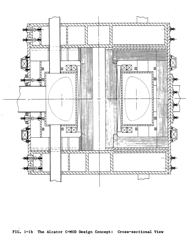
The design concept is illustrated in Fig. 1-1. The major part of
the poloidal field system, including the OH transformer is located inside
the TF coil. The latter is of rectangular construction and uses sliding joints at each of the four corners. This design largely eliminates
tensile loads in each leg of the TF coil, and permits rapid disassembly, allowing relatively easy access to the pf system and the vacuum chamber. The poloidal field system design is not yet fully optimized; at this
1-6 ... lop f3b <_0 CIO <30 <:W Q0 --------- -rop AA W-1
N N N N N N\ N~N N N N \ N N \ -~
I!
In z zH.
74
I 4 7 / / 4 /FIG. 1-lb The Alcator C-MOD Design Concept: Cross-sectional View
1-7 Ii I I.
zmR
N'\ WiI I I IiIh
o"II
iI fI 1111A
M-1-8
point we only illustrate what we expect will be representative of the
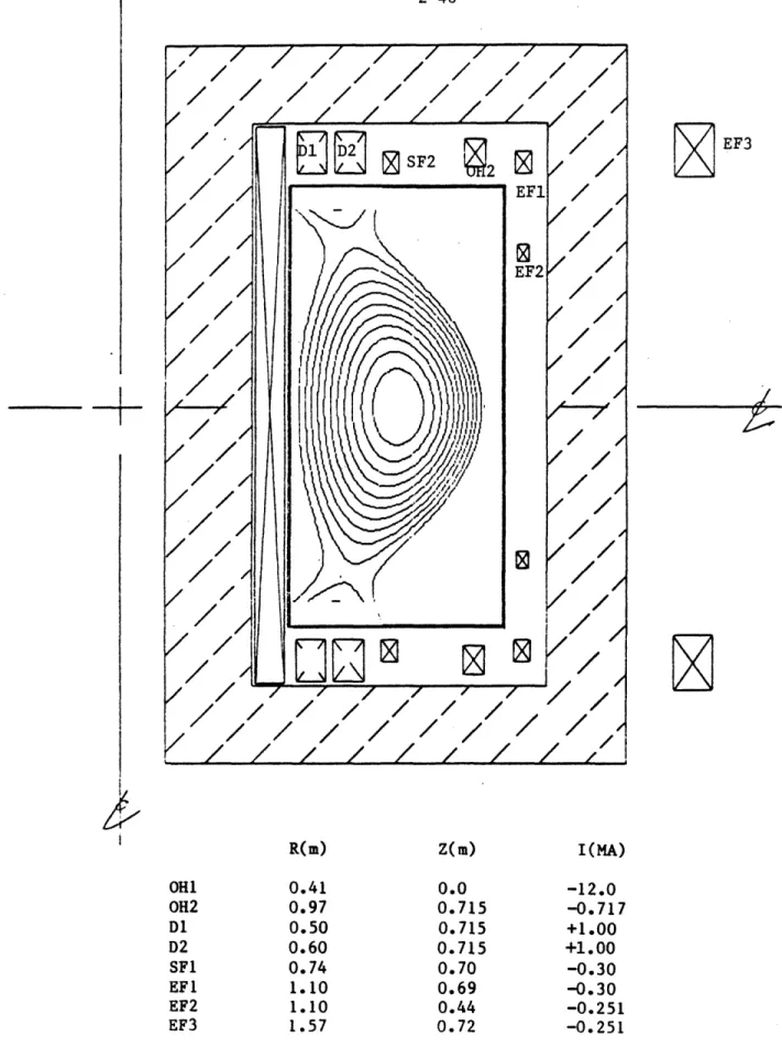
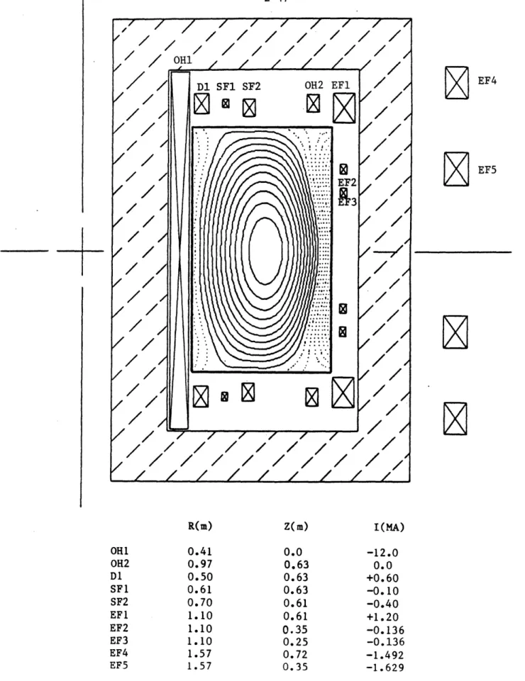
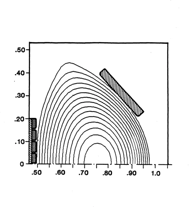
ultimate capability. Figure 1-2 shows a diverted plasma (Ip = 4 MA,
BT = 8 T, q4, = 2.6, K ~ 2) in which the distance between separatrix and
a divertor target plate can be made larger than the neutral mean path.
In this case, high-recycling divertor action is expected to occur.
With modification of the coil currents and relatively minor modifica-tion of the PF coil set, highly elongated (K 2.5), moderate aspect
ratio (A m 3) plasmas can be produced. (See Section 2.3 for examples.) Our intention is to capitalize on the significant increase in current at fixed q(, due to strong elongation (q I ~ 1 + K2), thereby permitting
optimization of confinement and overall performance.
Further optimization of the pf design should allow plasmas with high
triangularity and modest indentation to be created. Such plasmas are
expected to be close to the shapes required for optimum stability against
ballooning modes at high p. (See Appendix B and Ref. [II-1c] cited there-in.) While high p studies would require additional RF heating power com-patible with lower field operation, the baseline design can be used to
study axisymmetric stability and confinement optimization of these
ad-vanced shapes at low to moderate p.
The substantial qualitative improvements over Alcator C are the
capa-bility for elongated, highly-shaped equilibria; greatly increased access
for RF heating, power removal, and diagnostics; and an expanded
boundary-divertor configuration for impurity control and confinement enhancement
(H-mode). The baseline design provides for approximately 6 MW of RF
heating in the ion cyclotron range, using the Shemya equipment acquired several years ago for the Alcator C program. The extended performance
1-9
+
7/
'7
/
7//
/
~EFi
-7/
O/
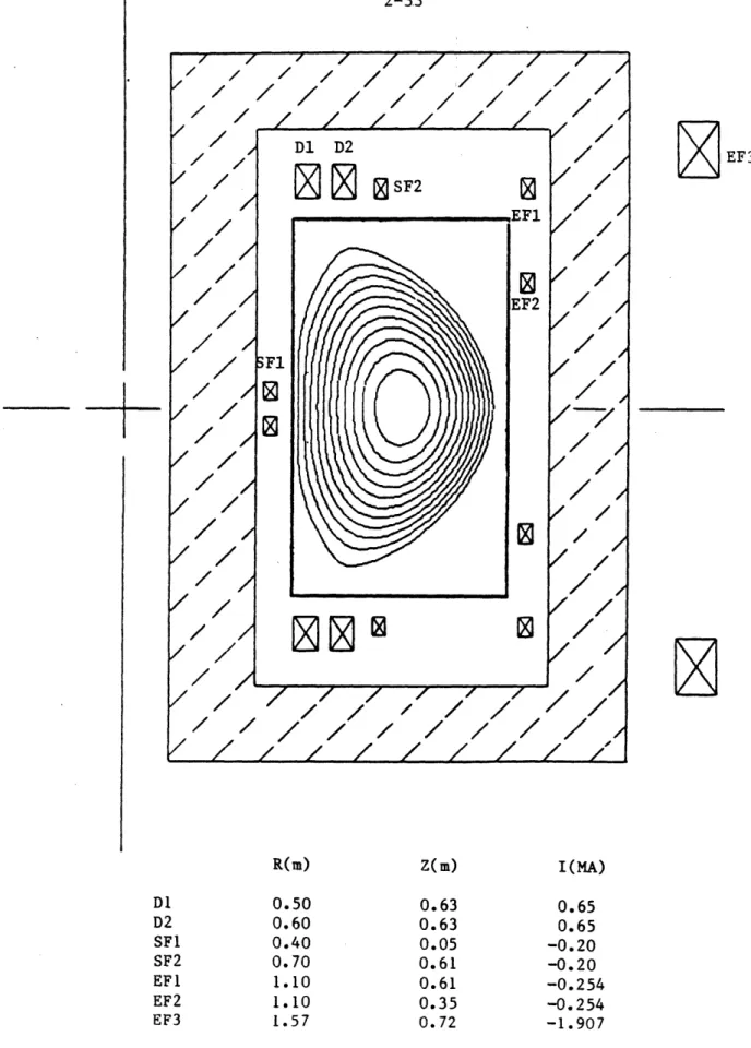
FIG. 1-2 A diverted plasma equilibrium in Alcator C-MOD. BT = 8 T,
= 4 MA, qp = 2.6, K 1 1.9. The coil currents in MA are:
D1l:1, D2:1, SF2:-0.3, EF1:-0.3, EF2:-0.26, EF3:2.6.
1-10
mode utilizes 10 MW of ICRF power. This power may be supplied in whole or in part by FMIT transmitters. In either case, a collaborative effort
with RF heating specialists from PPPL is anticipated. The details of
this collaborative arrangement await a successful C-MOD review and
defini-tion of a nadefini-tional ICRF program.
The basic C-MOD engineering and expected plasma parameters are shown in Tables 1-1 and 1-2 respectively, compared with two representative
com-pact ignition experiment designs. The machine is an approximate
full-field, half-scale version of ISP, the compact ignition device under
current study at PPPL. It is actually closer in size to Ignitor but the
design field is somewhat lower (10 T vs 13 T). Nevertheless, the projected maximum density (~ 1021 m- 3) is close to that anticipated in an
Ignitor-like device. Note that the wall loading is comparable to that under
ignited, high-P conditions in the ISP; it is also typical of that expected
1-11
TABLE 1-1
PROPOSED ENGINEERING PARAMETERS
C-MOD C-MOD ISP IGNITOR
(7.5 T) (10 T) (PPPL) Major Radius (m) 0.75 0.75 1.6 1.0 Minor Radius (m) 0.25 0.25 0.53 0.4 Magnetic Field (T) 7.5 10 8.9 13 Elongation (Nominal) 1.8 1.8 1.6 1.6 Triangularity 0.3 0.3 0.4 0.2
Plasma Current (MA) 3 4 7.8 10
Flat-Top Pulse (s) 1 1 5 0.5
Flat-Top Pulse @ 5 T (s) 10 20 -
-Volt-Seconds (Webers) 12 12 26 20
RF Heating (MW) 6 10 30 0-10
Average Heat Flux (MW/m2) 0.6 1 0.81) 3.61)
Plasma Surface Area (m2) 9.6 9.6 43.5 20.5
Stored Energy Required (MJ) 350 640
1-12 TABLE 1-2
EXPECTED PLASMA PARAMETERS
C-MOD C-MOD ISP IGNITOR
(7.5 T) (10 T) (PPPL)
Peak Densityl (x 1020 m- 3) 7 9.3 3.9 9.1
Peak Temperature (keV) 4-8 6-12 20-30 20-30
Beta (%) 1.6-3.1 1.7-3.5 3.1-4.7 3.4-5.1
Troyon Beta Limit (%) 4.8 4.8 5 5.8
Maximum Average Pressure (atm) 7 12.4 15 34
1 Assumes Murakami limit, n0 = 0.7 B/R
Comparing the magnet design of C-MOD to that in the ignition devices
one finds that the TF current density is about two times higher than in ISP. Consequently, the flat-top magnet pulse length is limited to being
one quarter as long (1s vs 4s). Assuming a NeoAlcator-type of energy
confinement law, the ratio of pulse length to confinement time would be
about the same. It is interesting to note that the ratio of pulse time
to skin time in C-MOD will actually be longer relative to ISP since
C-MOD would operate at lower temperature.
1.2.2 Physics Performance
The expected physics performance of C-MOD operating at 7.5 T and
10 T is summarized in a T-nTE plane in Figs 1-3a and 1-3b. The
antici-pated locus of operation of an ignition device (Q > 50) is shown for
com-parison. These results were obtained from a simple O-D power balance in
1-13
Alcator C-Mod Performance
B=7.5 T,
I=3
MA
40
20
10
4
2
1
IO I 1111 I I lullDT=
=5
R(NB)
K
JET-w ... C.
mmml
I I I III
N-Tau (W10
2 0
I I I *3 all.10
-
3
s-m)
FIG. 1-3a Expected performance of Alcator C-MOD at 7.5 T. The solid lines labeled KG, 2 x KG and NA correspond to use of Kaye-Goldston, 2 times Kaye-Goldston and NeoAlcator scaling laws, and the auxiliary power varies from 0 to 6 MW along these trajectories.
-
TFT
0
TFTR(OH) *AlcC
0.1
I
I I
I I Bill
I
I
I
-I I a A a
1 l 1 - 1 q '4 11 , tj I, oj 11 4jfl " 111 11 - 'I-, , , , r 1 -11 11N A
1-14
Alcator C-Mod Performance
B=10
T,
I=4
MA
DTD
RDT
B
KG
R (NB)
-40
20
10
4
2
DT
0
KG
NA
0
TFTR
(OH)
AC
I I I 111111I
N
2 0
N-Tau
MXO
1 I a I I It L10
-3
sm )
FIG. 1-3b Expected performance of Alcator C-MOD at 10 T. The labels have the same meaning as in Fig. 1-3a, and a maximum auxiliary power of 10 MW (absorbed) is assumed.
JET
0
0
.4-0
4-0
0
a.
E
4,
0
h. 4.-Ca,
(U) -T
.- TFT
I I
0.1
I
I
I I I I I I I
-M
1-15
T(r) = To(1-(r/a)2)Mt and n(r) = n0(1-(r/a) 2) n. The profile indices mt
1 and mn = 0.5 have been used in Fig. 1-3 and the peak density has been set at the Murakami limit, n0 = 0.7 B/R. The available auxiliary power was assumed to be 6 MW at 7.5 T and 10 MW at 10 T. The performance has been evaluated using NeoAlcator, Kaye-Goldston and twice Kaye-Goldston energy confinement laws. For each model, the lowest temperature corresponds to
ohmic heating and the highest to full auxiliary power, i.e., 6 MW @ 7.5 T and 10 MW @ 10 T. The last two confinement laws typify results which may
be expected from auxiliary-heated tokamaks and the factor of 2 variation incorporates the anticipated variation arising from the L-mode to H-mode
transition. In the absence of the bremsstrahlung loss, a confinement
scaling of the form tE P~Y where P is the total power results in the
T-n-vE trajectory - TT-V = const where v = (1-y)/y. The high current (4 MA
at 10 T) ensures that even L-mode confinement as determined from NBI ex-periments will lead to plasma regimes comparable to those predicted by
the NeoAlcator model.
1.2.3 Magnet Design
The compact ignition devices currently under study require magnet
systems which represent an advance in the state-of-the-art beyond the
high power density devices represented by the current generation Alcator
C and Frascati -tokamaks. One of the major goals for the C-MOD device is
to model a representative set of the required advanced concepts.
A conceptual design for the C-MOD device has been developed, and is based on the "jointed rectangular coil" concept under study at PPPL for the compact ignition device. This -concept uses an external frame to
1-16
reduce the tension loads on the TF magnet. When the external frame is combined with sliding joints in the TF coil, it is potentially possible to remove all the tension loads, hence only the radial compression loads remain to limit the magnet design. This offers the possibility of
achiev-ing ignition conditions in devices of the 1.5 meter major radius class.
The inclusion of joints in the TF coils opens up another major advan-tage, namely the ability to remove internal components in a relatively
straightforward manner. The vacuum chamber can be made in one piece, and
PF coils internal to the TF coil can be used to provide a controllable divertor configuration, and to provide adequate volt seconds. (The same comments apply to the large elongation or small aspect ratio versions of
the machine.) The use of these design concepts in Alcator C-MOD will
result in a flexible, easily serviced configuration, prototypical of ISP, as well as instrumental to advanced shaping experiments.
1.2.4 RF Heating
The C-MOD will greatly extend the limited RF access available in
Alcator C. The device will have 12 horizontal ports of approximately
15 cm width. This access will allow a major physics program to be carried forward on high density RF heating and advanced concepts experiments and
facilitate development of antennas for the ignition experiment. Since
the C-MOD field will be the same range as in the ignition device, the same frequencies and heating scenarios can be used, for example, minority H with a transition to second harmonic D in the frequency range 120-150 MHz.
1-17
It is proposed to use either the FMIT sources, with the PPPL RF Group carrying a major responsibility for the RF systems in collaboration with MIT, or to use the available FPS-17 radar sources obtained from the U.S.
Air Force site at Shemya several years ago. The development of the FMIT sources for use on Alcator C-MOD has the additional advantage that these
systems could be transferred to ISP when that device becomes operational.
The MIT FPS-17 radar transmitters, with some modification, would be em-ployed to investigate alternative heating schemes, such as ion Bernstein
waves at 3/2 wcH, and fast waves at 2
WCH-1.2.5 First Wall Protection
The high-power-density plasma operation in C-MOD will require
devel-opment of first wall protection and collectors which will in turn be proto-typical of the ignition experiment. Heat fluxes will be comparable with
the ignition experiment under the sub-ignited conditions.
The baseline design for Alcator C-MOD employs an expanded-boundary
poloidal divertor for controlling plasma edge conditions since present
experience world wide indicates impurity control to be a major need in
RF-driven plasmas, and the divertor provides the most promising solution.
Additional advantage is gained by use of the divertor, as evidenced by
the transition to H-mode in NBI-heated discharges. Operation will be
compared with pumped limiter operation in order to determine whether or not it will be necessary to install a poloidal divertor in the compact
1-18
1.2.6 Device Flexibility
The use of a fully jointed TF magnet concept in C-MOD can add a great
deal to the future flexibility of the device. After removal of the upper support structure, the upper TF legs can be removed, allowing the central TF core to be removed. Different PF coil sets and TF cores could then be
installed to allow alternate magnetic configurations. For example, re-placement of the inner TF leg would allow an elongation of K = 3 but at
lower aspect ratio, A < 3. Installation of a strong bean-shaping coil is
also easily accomplished. (Mild indentations are already permitted in
the baseline load assembly.) By substitution of an alternate central TF
leg, a very low aspect ratio (A = 1.7) plasma with a central field of 1.5 T
could be generated. Thus, after the major mission of support to the
ignition experiment has been fulfilled, the flexibility of Alcator C-MOD
permits rapid reorientation toward the tokamak concept improvement area.
1.3 Baseline and Extended Performance Options
Two basic design options are presently under consideration for
Alca-tor C-MOD. In the first, the 225 MVA alternator donated to the Plasma
Fusion Center for use in Alcator C, remains as the primary energy source.
Some overspeeding, either by means of a gear box or inverter variable-speed
drive s stem, will be added so that a total energy of about 350 MJ can be extracted. This results in a maximum field capability of 7.5 T and would
yield, :or example, the performance shown in the shaded region in Fig.
1-3a. The RF heating required for this option would be supplied by the
Shemya sources, acquired from the Air Force several years ago, and
pres-ently being used for ICRF experiments on Alcator C. This baseline option
1-19
costs and, as will be shown in Chapter 7, can be accommodated on a fixed
Alcator C program budget over the next three fiscal years,.FY '86-FY '88.
Operation of the baseline device would commence at the beginning of FY '89. In the second option, a new rotating machine would be added to the PFC resources, and a maximum energy approaching 1 GJ could be extracted for use in Alcator C-MOD. The maximum field capability could then be 10 T
and the improved performance shown in Fig. 1-3b would be expected.
Sig-nificantly longer pulses would also be permitted at the 7.5 T maximum field of the baseline option. The Shemya sources may no longer be useful for
heating at 10 T (depending on the success of the Bernstein wave technique
at 1.5 wth) and consequently additional ICRF power would need to be
deployed. At present, we are considering use of several FMIT transmitters which would be modified for this purpose under a collaboration with PPPL.
The cost of this extended performance option would be approximately $22 M
not including RF power. It is impractical to attempt to bear this cost
on a flat Alcator program budget.
At the present time, negotiations are underway with the U.S. Air
Force which has expressed interest in installing a new rotating machine at MIT with stored energy well-matched to the extended performance needs of Alcator C-MOD. Should these negotiations prove successful, it will become possible to build a device with extended performance capability within the constraint of a flat Alcator operating budget. The
CHAPTER 2
PLASMA PHYSICS CONSIDERATIONS
2.1 Introduction
As an upgrade. to the highly successful Alcator C device, Alcator
C-MOD provides improved access and impurity control as well as advanced
shaping capabilities which permit higher currents than are attainable on the present device. These enhancements are expected to lead to improved plasma performance in terms of absolute parameters, such as total
pres-sure, confinement time, and n-eT and to permit study of relevant phenomena in novel regimes of tokamak operation.
The physics program on Alcator C-MOD is aimed at extending the tokamak database in the areas of transport, RF heating, MHD stability and impurity control. The operating regimes in which these studies will be carried
out are close to those characteristic of ignited plasmas and represent an
appreciable advance over present experiments. The full-field parameters selected for Alcator C-MOD (B2 aKl/2 > 30) offer the potential of ohmic
confinement times in excess of 200 msec and nrE > 1020 sec-m-3. The
rel-atively small aspect ratio and large elongation permit high current
opera-tion (Ip > 4 MA) and consequently good confinement is expected even for strongly auxiliary heated plasmas. Standard L-mode scalings, e.g. Kaye-Goldston, predict confinement times similar to the ohmic values, while H-mode scalings correspond to larger than neo-Alcator confinement times. The initial RF heating system (baseline case) provides up to 6 MW of
ICRF, which, even for L-mode confinement, is sufficient to produce plasma
pressures above 3 atmospheres (stored energy of order 1 MJ) with central
temperatures in the range of 5 to 10 keV and density ne ~ 5 x 10²⁰ m 3 ,
2-2
Tokamak transport in this parameter regime, characterized by high pressure at rather low Op, is essentially unexplored experimentally, and
extrapola-tions from the present empirical scalings are highly uncertain. The
database for transport in auxiliary heated plasmas is drawn primarily from neutral beam injection experiments in which the confinement degrades
significantly from the ohmic level. The confinement time is generally
found to decrease with increasing heating power, so that the stored energy increases approximately as the square root of the power, rather than linearly. Similar efects have been observed in RF heated plasmas. In the present case, the standard scalings derived from this database (e.g.
Kaye-Goldston) predict confinement times larger than the neo-Alcator ohmic
value; roughly speaking this is due to the relatively high ratio of
cur-rent to plasma density characteristic of C-MOD operation. In present
experiments this condition holds only for somewhat downgraded operating parameters, for example with Murakami parameters well below the density
limit.
The actual behavior of confinement, and therefore the plasma param-eters obtained in Alcator C-MOD, will depend on the physics underlying
the presently observed behavior, i.e., the mechanism through which trans-port appears to depend on input power. One possibility is that transtrans-port
in auxiliary heated discharges is driven by resistive MHD turbulence, so
that the relevant parameter is not power as such but Op or the normalized
pressure gradient. It has also been suggested, by Ohkawa, that the power
density drives turbulence through distortions of the velocity space
dis-tribution function, leading to enhanced transport. In this case the
parameter of interest is of the form (P*/nTvee), where P* is the effective
2-3
function. Recently, considerable attention has been focused on the inter-pretation of the observation that temperature profiles tend to retain a canonical shape, independent of the auxiliary power deposition profile. This "Principal of Profile Consistency" may be related to the current density profile, for example as a manifestation of the stability criterion for tearing modes, or it may arise from a dependance of the thermal
dif-fusivity on temperature or pressure gradients. The Alcator C-MOD
experi-mental program will have as a principal focus the clarification of these
physics questions.
The principal heating technique to be employed on Alcator C-MOD will
be RF in the ion cyclotron range. This technique is also presently
favored for near term ignition experiments and will be employed on several existing experiments, including ASDEX, JET and JT-60. The unique features
of the ICRF heating experiments on Alcator C-MOD arise from the high
target plasma density (Fe > 5 x 10²⁰ m- 3), toroidal field (7 < BT < 10 T),
and average power density (3-5 MW/m- 3). While our understanding of the
physics of ICRF heating has grown significantly over the past decade, the
experimental database is, with the exception of low power experiments on
Alcator C, restricted to much lower fields and densities. The coupling to the plasma and the evolution of non-thermal distribution functions may be expected to differ markedly from lower density experiments.
ICRF heating on Alcator C-MOD will be carried out using both the fast wave, interacting at either the majority species second harmonic or at the fundamental resonance of a minority ion component, and the ion
Bernstein wave. In the case of fast wave heating, the antenna must be
2-4
conversion losses, but small enough not to reduce ki, since the damping mechanism for the fast wave is a finite Larmor radius effect. The port width in Alcator C-MOD has been designed to accommodate either loop or
coupled cavity type antennas which satisfy this requirement. Ion tail
formation may occur in the majority species in the case of second harmonic
heating or in the minority for fundamental damping. While the presence
of a high-energy tail leads to increased damping for the wave, it may also be detrimental in terms of increased losses, transport degradation, and impurity generation. The wide range of power density and
collisional-ity accessible in Alcator C-MOD will enable us to investigate these effects in detail.
In the case of Ion Bernstein Wave heating, short wavelength
electro-static waves with a frequency corresponding to an odd half-harmonic of the gyrofrequency of the majority species are absorbed by either linear or
non-linear cyclotron harmonic damping near the plasma center. Since
uVk1 ~ vTi, the bulk of the distribution is heated and no ion tail
forma-tion is expected. Since the desired wave polarizaforma-tion at the launcher is
E i B, as in the case of lower hybrid heating, waveguide launchers may be employed. A limited amount of experimental work with this technique has
been carried out at low power and density on PLT and JIPP-T-II-U, and higher density experiments are in progress on Alcator C. In the former cases, the results support the interpretation that non-linear effects are
responsible for the absorption. High power density experiments on Alcator
C-MOD will increase the understanding of the physics and determine the
2-5
As has been mentioned, a major advance in Alcator C-MOD relative to Alcator C is the incorporation of elongated D-shaped plasmas. This fea-ture, together with the reduction in aspect ratio from 3.9 to 3, allows C-MOD to operate with much higher currents and I/aB values than its predecessor while retaining comparable values of B/R. In addition, the
design incorporates a poloidal divertor capability for impurity control
and as a tool for influencing the edge parameters and transport. The
role of elongation and shaping on plasma stability and transport remains
an important issue in the understanding and optimization of tokamak performance. The Alcator C-MOD design provides sufficient flexibility to
investigate these effects systematically. One aspect of these studies
will involve the relative importance of elongation and aspect ratio in both confinement and stability, which will lead to improved configurations
for advanced tokamak experiments.
Despite the demonstration of very high n0'uE values on Alcator C,
the limits of ohmic tokamak plasma performance are still unclear. In the
case of Alcator C, neoclassical ion thermal transport limits confinement at the highest accessible densities and currents. This limit turns out
to be similar to that which might be predicted for H-mode scaling, taking
the total power equal to the ohmic power. In the case of Alcator C-MOD, on the other hand, the higher poloidal field and reduced collisionality results in relatively larger values of the neoclassical ion confinement
time. Morever, for full-field operation the central current density, which scales as (B/R)(K + K-1), is similar to the highest values in Alcator
C and essentially equal to those of proposed high field ohmic ignition
2-6
to the question of ohmic tokamak performance limits and the prospects for pure ohmic ignition.
In the remainder of this.chapter we present more detailed discussions
of anticipated plasma parameters, RF heating physics, MHD equilibria and stability, and divertor and limiter design for the baseline configuration.
In addition we present some results of calculations pertaining to
full-field (10 Tesla) operation and alternate geometries related to the concept improvement aspects of the Alcator C-MOD program.
2.2 Plasma Parameters - Transport Calculations
2.2.1 O-D Modeling
We have carried out O-D confinement modeling in order to obtain a first approximation estimate of the parameter range of the Alcator C-MOD
plasmas. In this section we present results for both ohmic (neo-Alcator)
scaling and H- and L-mode auxiliary heating scalings, for both baseline
and extended full-field operation.
The form of the neo-Alcator scaling employed in these calculations is ,NA - 1.9 x 10- 2 1 R2.04al.04 K0.5
which is identical to the original formulation [2.2-1] with the exception
of the dependence on elongation K. The favorable linear dependence on
q reported by TFTR [2.2-2] and JET [2.2-3] is not included, consistent with experimental results on Alcator C for q > 3. It may be expected
that actual confinement will be somewhat reduced at lower q values due to sawtooth effects.
2-7
To estimate the possible degradation in confinement at elevated power density (or e4p), we have adopted the Kaye-Goldston expression [2.2-4]
KG 1.24 6 R1 65. a 0 .4K.8-0.58
KE = 0.55 I1 .(MA)B- 0*0 9(T)i0.26(1020m3)R1 a-0 4 9 0 2 8ptOt ) The above regression fit was derived from L-mode neutral beam discharges
and has been observed to be consistent with ICRF results on several
machines. For possible H-mode operation we have taken the rather crude estimate r = 2G
In these O-D scalings we have not taken account of ion heat conduc-tion losses, which are in fact found to be important in high density Alcator C discharges. However in the present case this omission may be justified a posteriori from the observation that, for typical operating
conditions, e.g. R = 5 x 10² 0 m-3, I, = 2 MA, B = 7.5 T, the neoclassical
ion confinement time is a factor of order five or more greater than A
and exhibits a scaling with current similar to that of Kaye-Goldston. On
the other hand, anomalous ion transport with a scaling different from neoclassical, as suggested by the Alcator C experiments, could
signifi-cantly impact the global confinement. Ion transport is, of course,
explicitly considered in the 1-D simulations described in the following
section.
The operating space for Alcator C-MOD, in terms of the (1/q) vs (nR/B) (Hugill) diagram is estimated on the basis of Alcator C experiments. Thus,
we take the density limit to be given by
nR/B < min[0.6,1.6/qc
2-8
parameter obtained on Alcator C with pellet injection. For our baseline parameters the density limit is then approximately 6 x 10²⁰ m- 3. Based on experience on Alcator C and other devices we may conservatively estimate the current limit to be given by q, > 2.5 for limiter discharges and q,
>
3 for divertor or expanded boundary operation. For the baselineconfiguration these limits correspond to approximately 4 MA and 3.3 MA
respectively.
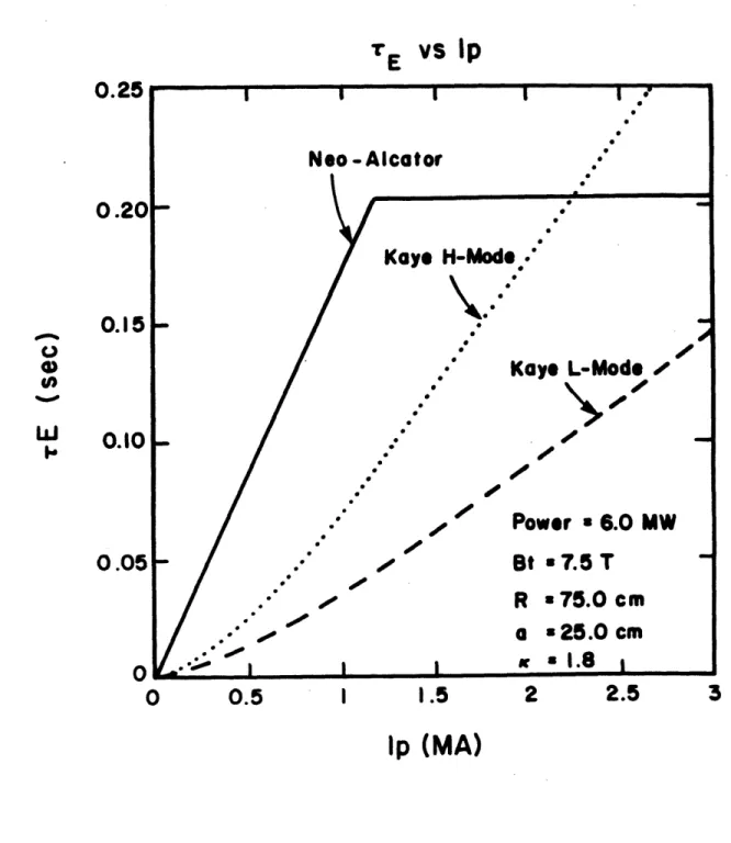
In Figs 2.2-1 and 2.2-2 we depict the scaling of global energy
con-finement time for the baseline configuration as a function of total
density and current for neo-Alcator and Kaye-Goldston scaling laws. We note that the H-mode scaling, as defined above, always exceeds the neo-Alcator value by a significant factor. If we assume that the total
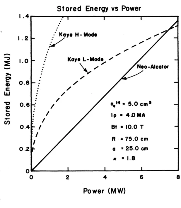
con-finement will be given by some combination of the empirical scalings, the
stored energy should vary roughly as indicated by the lower dashed line
in Fig. 2.2-3, if L-mode scaling is appropriate, and be essentially equal
to the neo-Alcator prediction if H-mode obtains. The total power
avail-able in the baseline configuration
Ptot = T1RF + POH v 6 MW
where the source power from the FPS-17 transmitters is PRF - 6MW, the transmission and coupling efficiency T1 w 0.7, and POH for the parameters
shown is of the order of 2 MW.
If we assume a Gaussian profile for the electron and ion temperatures
we can estimate
2-9
TE
vs Density
4
6
n
(10
1 4/cm
3)
FIG. 2.2-1 Global confinement time as a function of density for baseline
configuration of Alcator C-MOD. For L-mode scaling the effective confinement may be expected to follow the lower dashed curve.
.35
.3
.25
.2
CO I I I I -Neo-Alcator
0.
-Kaye L-Mode
---
Kaye H-Mode
*0000,0,00000-
.
1p=3.0
MA-Power=6.
eomw
Bt=7.5 T
R
=75.0
cm
.
a=25.0 cm
K
=1.8
0* ii151
.1
.25
0
2
8
10
2-10 TE
vs
Ip
I
Neo-Alcator
-K
.0-0
S..'-
.-
e
.- /.- 0
--0.5
iye H-Mode.
0Kaye L-Mode
/ lePower
a
6.0 MW
Bt
a
7.5
T
R
a
75.0 cm
4e -4,a
le
1.5
2
Oe.25.0 cm
.1.8
,2.5
3
1p
(MA)
FIG. 2.2-2 Global confinement time as a function of plasma current for the baseline configuration, with density limited by the con-straint on the Murakami parameter.
i
W
0.25
0.201
I .~0.151
C)w
gin.
0.101
0.051
0I
0
I
I
00
I
2-11
Stored Energy vs Power
2
3
Power (MW)
4
FIG. 2.2-3 Plasma stored energy as a function of total input power for typical Alcator C-MOD parameters, with different transport assumptions.
1.2
1.01
LOC
w
0
,8
.6
.4
.2
I I .- I I I-s-
Neo-Alcator
-- --.-
Kaye L-Mode
Kayo H-Mode
0010-
*3
n*4-=
5.0
li/*
lp=3.0 MA
Bt=7.5 T
R
=75.0
cm
a=
25.0
cm
0K 0: . 00
I
5
6
,I - I [d tI' I iil [I - , 2-12 where <Te + Ti> aT 2 0 a = - (-) w 1.5--TeO + TiO a qa
and aT is the gaussian width of the temperature profile and qa is the edge safety factor. We may then estimate the operating temperature from the
stored energy as
1 1 W
kT 0 -
-3a ff V
where W = P is the plasma stored energy and V - 212Ra2K is the plasma
volume and we assume TeO = Tio - To. For the conditions of Fig. 2.2-3,
we predict central ion temperatures between 5 and 7 keV with line average
density of 5 x 10²⁰ m-3 and 6 MW total input power.
Enhanced performance can be achieved in Alcator C-MOD by installation of a new alternator, permitting the toroidal field to be increased to 10 Tesla, and by use of the FMIT RF sources, with a total power of 10 MW. The 10 Tesla option is discussed in Appendix A, and the FMIT sources are described in Section 2.5 of this chapter. Here we present the predictions
of the O-D scaling models for this operating scenario. Again taking
approximately 70% coupling and transmission efficiency for the RF and of
the order of 1 MW residual ohmic power, we find that L-mode scaling would
begin to dominate at a density of ne - 5 x 10²⁰ m-3 As can be seen
from Figs 2.2-4 and 2.2-5, the stored energy under these conditions should exceed 1.3 MJ, corresponding to a plasma pressure of approximately
5 atmospheres at a confinement parameter ie -r 2O m-3 sec. These
2-13
rE
vs
Density
4
6
n
e
(10
4/cm
3)
FIG. 2.2-4 Global confinement time as a function of density for full-field operation of Alcator C-MOD. Contours of constant Lawson parameter are shown by the double dashed lines.
.35
.3
.25
00
Cow
.
001.0*Kaye H-Mode',
- Kaye L-Mode
..
--n.
.. 6cri4--s10
1p 4.0 MA
R 75.0 cm
Power=8.0 MW
a=25.0 cm
'KBt=10.0
T
=1.8
nT=1 3C i- s
---
---...
-: |-31
.2
.15
.1
.05
0
2
8
10
I I
-2-14
0.81
1.4
0
2
4
6
8
Power (MW)
FIG. 2.2-5 Stored energy as a function of input power for parameters
typical of full-field operation of Alcator C-MOD. For these parameters, the L-mode and neo-Alcator predictions coincide at the highest power.
Stored Energy vs Power
Kaye H-Mode
-.?
Kaye L-Mod*
/-1000
KNeo-Alcotor
/
n.1
5.0 cm3
-:
/
1p
a4.
MA
Bt
a 10.0 T
R
=
75.0 cm
a =
25.0
cm
-I
=1.8
I 2
0
0'"*
0
60
Cl)
0.6
0.4
0.2
0
I
2-15
with equivalent Q values near 2, in excess of the performance predicted, by
the same models, for JET, JT-60, or TFTR. If H-mode scaling is obtained, still higher parameters may be expected as we increase the density to the
Murakami limit. At a line-averaged density of 8 x 10²⁰ m- 3, neo-Alcator
scaling predicts a pressure of 8 atmospheres and RetE > 2 x 10²⁰ m-3 sec.
It is worthwhile to note that there are large uncertainties in pro-jections based on these empirical scaling formulas. The ohmic confinement scaling employed here is consistent with experimental results from Alcator
C at similar fields and densities, and the geometric scaling appears to
be well founded, with the possible exception of the K-dependence.
Never-theless, there remain some discrepancies with other experiments, notably
the strong dependence on safety factor observed on the large tokamaks
TFTR and JET. In the case of the L and H-mode scalings, the extrapolation
to our parameters is greater and the level of confidence consequently reduced. We may for example, compare the predictions of the earlier
Goldston L-mode scaling [2.2-5], based on a similar but more restricted database and employing slightly different methodology:
TG = 0.037 I(MA)i0.5R1.75a-0.37P-0 5
p tot*
While the two L-mode scalings agree quite well in the regimes for which they were derived, they differ by more than a factor of two when
extrap-olated to typical C-MOD operating parameters. The major discrepancies
between the two expressions involve the dependence on density and current density, which are the quantities requiring the largest extrapolation from the original auxiliary heating database.
2-16
An additional uncertainty arises from the method by which we combine the scaling laws in the "transition" region, assuming that L-mode scaling
(or Goldston H-mode) holds. Goldston has suggested, on purely empirical
grounds, that the transition is best fit by a quadrature sum
1 2 1 2 1 2
(--) = (--) + ( )
4UX
while a straightforward interpretation in terms of independent diffusion
coefficients would imply
1 1 1
NA 'AUX
and a model based on most efficient removal of free energy might suggest
-E = min[NA, AUXj
In sketching the dashed curves in the transition regions of the preceding
figures, we have essentially taken the latter interpretation, which also
produces the most optimistic prediction. The purely diffusive assumption would lead to maximum confinement times which were lower by about a
factor of two. However such an assumption severely underestimates the maximum confinement times observed in ohmic discharges in Alcator C, as
in fact does the Goldston prescription if neoclassical ion losses are
also taken into account. The actual experimental results will provide a
good experimental test of this issue, and therefore yield information about the linearity of the transport mechanism.
2-17
2.2.2 1-D Simulations
While the steady-state O-D modeling described above serves to esti-mate the parameter range to be expected, 1-D modeling has been also been employed to investigate profile and time-dependent effects, and to more
clearly delineate the effects of different transport assumptions and
engineering constraints. Simulations were carried out using the ONETWO
code [2.2-6]; all the results reported here have been obtained using the
purely 1-D section of the code with elliptical flux surfaces.
There is at present no consensus on the appropriate form for local
transport coefficients in tokamak plasmas. As indicated above, the
fundamental mechanisms responsible for anomalous transport are unknown.
Further, theoretical treatments of the different possiblities (e.g. drift
mode turbulence, resistive MHD activity, etc.) are in general unable to
predict absolute magnitudes for the diffusivities arising from various instabilities, but can indicate scalings with experimental parameters. Alternatively, purely empirical values of the transport coefficients may
be extracted from analyses of experimental data, and then examined for
consistency with fundamental theoretical constraints. In applying any of
these transport coefficients in a predictive manner, it is important to
recognize that the results may have even less relevance to the real world than those of global O-D scaling laws. Our principal purpose in carrying out such 1-D simulations is to investigate phenomena which are explicitly time and/or space dependent, and as far as possible to compare the
impli-cations of different assumptions regarding unknown physics. We may there-fore evaluate, on the one hand, the extent to which our design is optimized
2-18
ability to conduct experiments which may help distinguish between differ-ent mechanisms and thereby remove the uncertainties.
Our basic transport model assumes an ohmic transport contribution of the neo-Alcator form
KN n NA = 5.0 x 10²⁰ r/R2 + n (1)
whereC is the neoclassical electron thermal diffusivity, which is
negligible compared with the anomalous contribution except near the axis, where sawtooth activity is typically dominant. This expression is purely
empirical, and has been found to be consistent with experimental results
on Alcator C and other tokamaks during the ohmic heating phase. The
time-averaged effect of sawteeth on electron and ion transport have been
modelled by addition of an effective thermal diffusivity in the q
<
1region of the form
1
X Saw = Db(1 ~ 1 + (1/q - 1)2
Alternatively the sawteeth are modelled explicitly, with an internal
dis-ruption triggered either by the decrease of qO below some value, typically
.95, or by the calculated width of the m=1 island. The resistivity is taken to be neoclassical, as suggested by recent JET results [2.2-7].
As one model of the degraded transport observed in auxiliary heated discharges, we have taken an anomalous thermal conductivity of the form
Kux = 5.Op1'.On. 8rO*4B-2q2.2 -1 (2)
where p = neTe + niTi is the local pressure in units of keV/cm3, s is the