Design and Optimization of Actuation Mechanisms for Rapid Skin Closure Device
MASSACHUSTTS INSTtTE OF TECHNOLOGY by
JUN 2 8 2012
Andrew T. EricksonLBRARIES
Submitted to theDepartment of Mechanical Engineering
in Partial Fulfillment of the Requirements for the Degree of Bachelor of Science in Mechanical Engineering
at the
Massachusetts Institute of Technology June 2012
© 2012 Andrew T. Erickson
All rights reserved
The author hereby grants to MIT permission to reproduce and to
distribute publicly paper and electronic copies of this thesis document in whole or in part in any medium now known or hereafter created.
Sign atu re of A u th o r ... ...
=
... - . --.-. ---Department of Mechanical EngineeringMay 23, 2012
Certified by ... ...--- . ...--- ----Alexander H. Slocum Neil and Jane Pappalardo Professor of Mechanical Engineering
Thesis Supervisor
Accepted by... ...
oMe onn H. Lienhard V Samuel C. Col 1 of Mechanical Engineering
Design and Optimization of Actuation Mechanisms for Rapid Skin Closure Device
by
Andrew T. Erickson
Submitted to the Department of Mechanical Engineering On May 31, 2012 In Partial Fulfillment of the Requirements for the Degree of Bachelors of Science in
Mechanical Engineering
ABSTRACT
Innovative mechanism designs were explored for the actuation of critical components in a novel rapid skin closure device used to close long surgical incisions. The rapid skin closure device is
designed to speed up the wound closure process and achieve the aesthetic results of a plastic surgeon by automatically placing bio-absorbable adjustable clips in the dermal layer of skin along a surgical incision. Precise alignment of the wound edges, deployment of needles pre-loaded with clips, and the successful connection of the two clip ends inside the wound are critical for the proper function of the device. The iterative design of the actuating mechanisms for the skin alignment, needle deployment, and successful clip connection were accomplished in four prototypes. The first two prototypes demonstrated the proof of concept that needles could follow a pre-determined path and two ends of a clip could be reliably connected. The second
pneumatically actuated prototype connected over a hundred clips in a row and measured a repeatability of 98%. The third and fourth prototypes focused on refining the design into a production product by reducing the size, complexity, and cost. Many types of actuators and power transmission components were used, combined, and compared. It was found that the skin alignment could be reduced to a passive rail system that did not require an actuator. Furthermore, the needle and ejector pin motions critical for the success of placing a clip were combined into a single actuating motion. The combination was made possible by a series of nested cylinders separated by a stiff compression spring, and actuated by a slotted angled bar that optimized efficiency. All electronics were eliminated from the device with the inclusion of a manually actuated handle to drive the main slotted bar. The results from testing in human skin revealed that the needle deployment and clipping were successful, but the passive rail alignment failed due to the elastic nature of the tissue. Further refinement will be required to make the device production ready. However, the innovative designs from this research will have a significant impact on the success of the device as a product.
Thesis Supervisor: Alexander H. Slocum
ACKNOWLEDGEMENTS
First, I would like to give thanks to my Lord Jesus Christ for the opportunities he has blessed me with at MIT and the relationships with the people he has put in my life. One of the most
important people he has put in my life is my wife, Amy, who has stood by me these past four years with encouragement, understanding, and support. I would not be the person I am today without her. Also, I would like to thank my family for being there for me throughout my
childhood and college career always encouraging me to do my best and give thanks to the Lord.
Next, I would like to thank my teammates: Carmen Graves, Omar Carrasquillo, Faye Wu, Steven Lam, and the two doctors from MGH who worked with us, Dr. Jonathan Winograd and Dr. Kyle Eberlin, for all their hard work and dedication towards the goal of making the Rapid Skin
Closure project into a successful product. This project was also made possible by the valuable insights and advice from Nevan Hanumara, Professor Alexander Slocum, and Nikolai Begg. Thanks for being there at all hours of the day with helpful advice and difficult questions that forced us to push the envelope.
Finally, I would like to thank the staff at MIT's Hobby shop and Edgerton center for helping the team with any questions we had about machining and rapid prototyping.
This work was also supported by CIMIT under U.S. Army Medical Research Acquisition Activity Cooperative Agreement W8 1XWH-09-2-000 1. The information contained herein does not necessarily reflect the position or policy of the Government and no official endorsement
CONTENTS
ABSTRACT ... 3
A CKN OW LED GEM ENTS ... 5
CONTENTS ... 6
FIGU RES... 9
TA BLES ... ... 12
1 INTRO D UCTION ... 13
1.1 Opportunity... 13
1.2 W ound Closure M echanics ... 13
1.3 Risks of Conventional Practice ... 15
1.4 Alternative Approaches ... 16
1.5 Overall Project Goal... 18
1.6 Thesis Focus... 18
2 BA CKGROU N D ... 20
2.1 W ound Closure Strategy ... 20
2.2 Actuating M echanism s: Requirem ents and Goals ... 22
2 .2 .1 C o s t ... 2 3 2.2.2 Form Factor ... 23 2.2.3 User Interface... 23 2 .2 .4 F o rc e ... 2 4 2 .2 .5 S p e e d ... 2 4 2.2.6 Com plexity ... 24 3 Prototype 1 ... 25
3.1 Developm ent Goals... 25
3.2 Prototype 1 Final Design ... 25
3.3 A ctuator D esign ... 31
3.3.1 D esign Selection...32
3.4 R esults... 33
3.5 D iscussion ... 34
4 P R O TO T Y P E 2 ... 35
4.1 D evelopm ent Goals... 35
4.2 Prototype 2 Final D esign ... 35
4.2.1 A ctuation Steps...37
4.3 Skin A lignm ent D esign ... 41
4.3.1 Design Selection...42
4.3.2 A ctuation Steps...43
4.4 Ejector Pin A ctuation For Clips... 44
4.4.1 Reverse "Pen Click" Design ... 46
4.4.2 Ejector Pin Design Change...51
4.4.3 A ctuator D esign Concepts...51
4.4.4 Design Selection...52
4.5 N eedle A ctuation ... 53
4.6 R esults... 55
4.7 D iscussion ... 56
5 PR O T O T Y PE 3 ... 57
5.1 D evelopm ent G oals... 57
5.2 Prototype 3 Final D esign ... 57
5.2.1 A ctuation Steps...59
5.3 Com bined A ctuator D esign ... 62
5.3.1 Design Selection...65
5.3.1.1 Cam Concept... 66
5.3.1.2 Lead Screw Concept... 70
5.4 N ew A lignm ent D esign... 73
5.4.1 Design Selection...76
5.4.2 A ctuation Steps...76
5.5 M anual vs. Electric A ctuation ... 78
5.5.1 M anual Actuation Design ... 78
5.6 Design Change Due To Needle Concerns ... 82
5.6.1 Design Selection...83
5.7 Results... 85
5.8 Discussion ... 91
6 P R O T O TY PE6 ... 92
6.1 Developm ent Goals... 92
6.2 Prototype 4 Final Design ... 92
6.2.1 Actuation Steps...94
6.3 Reduction In Part Count... 99
6.3.1 Design Selection...99
6.4 Jam m ing Reduction In Com bined Actuation M otion...100
6.4.1 Nested Tube Design Selected ... 101
6.4.1.1 Nested Tube Concept...102
6.4.1.2 Actuation Steps...103
6 .4 .1 .3 B e n e fits ... 1 0 4 6.4.1.4 Assem bly Considerations ... 104
6.4.1.5 Actuation Bar Design...107
6.5 M anufacturing Considerations...108
6.6 Results... 110
6.7 Discussion... 112
7 CO NCLU SIO N ... 113
7.1 Sum m ary of Actuator M echanism Developm ent...113
7.2 Future Developm ent Strategy...114
7.3 Final Recom m endation ... 115
R EFEREN CES ... 116
A PPEN D IX A ... 117
FIGURES
Figure 1.1: Cross-section of wound showing the layers of skin... 14
Figure 1.2: Current wound closing procedure ... 15
Figure 1.3: Past devices that tried to solve the skin closure problem ... 17
Figure 2.2: Project strategy for wound closure in 6 steps... 21
F igure 2 .3 C lip design ... 22
Figure 3.1: Final design of Prototype 1 ... 26
Figure 3.2: Annotated model of Prototype 1 ... 27
Figure 3.3: Prototype 1 actuation steps 1-4 ... 29
Figure 3.4: Prototype 1 actuation steps 5-8 ... 30
Figure 4.1: Pictures of the final Prototype 2 Design... 36
Figure 4.2: Annotated model of Prototype 2 ... 37
Figure 4.3: Prototype 1 actuation steps 1-4 ... 39
Figure 4.4: Prototype 1 actuation steps 5-8 ... 40
Figure 4.5: Solid models of suction skin alignment mechanism ... 42
Figure 4.6: Suction skin alignment actuation steps ... 43
Figure 4.7: Depiction of asynchronous ejector pin and needle movement... 44
Figure 4.8: Critical ejector pin positions... 45
Figure 4.9: Annotated model of reverse pen click design ... 47
Figure 4.10: Reverse pen click concept actuation step 1... 48
Figure 4.11: Reverse pen click concept actuation steps 2-5 ... 49
Figure 4.12: Reverse pen click concept actuation steps 6-9 ... 50
Figure 4.13: New critical ejector pin positions ... 51
Figure 4.14: Pneumatically actuated ejector pin design ... 53
Figure 4.15: Optimized needle path geometry... 54
Figure 4.16: Needle bearing supports ... 55
Figure 5.1: Picture of inner components of Prototype 3... 57
Figure 5.2: Solid model of Prototype 3... 58
Figure 5.4: Prototype 3 actuation steps 1-6 ... 61
Figure 5.5: Solid model of Cam concept ... 66
Figure 5.6: Annotated model of Cam concept ... 67
Figure 5.7: Cam concept actuation steps 1-4... 68
Figure 5.8: Cam concept actuation step 5... 69
Figure 5.9: Solid Model of Lead Screw concept ... 70
Figure 5.10: Annotated model of Lead Screw concept... 71
Figure 5.11: Lead Screw concept actuation steps 1-4... 72
Figure 5.12: Solid model of passive rail alignment ... 76
Figure 5.13: Passive rail alignment implementation steps 1-4 ... 77
Figure 5.14: Solid model of manual actuator... 79
Figure 5.15: Pictures of manual actuator in action ... 79
Figure 5.16: Annotated model of the manual actuator ... 80
Figure 5.17: Manual actuator steps 1-3... 81
Figure 5.18: Change from curved to straight needle paths ... 84
Figure 5.19: Packaging challenges create off axis forces on bearings ... 85
Figure 5.20: Picture of passive rail alignment testing in pork belly ... 86
Figure 5.21: Alignment rod jamming condition ... 87
Figure 5.22: Jamming condition between wall bearings and needle path slots ... 87
Figure 5.23: Free body diagram of forces angled actuation bar forces ... 89
Figure 5.24: Graph of inline forces versus change in actuation bar or linkage angle... 89
Figure 5.25: Friction Losses with respect to change in angle of actuation bar... 90
Figure 6.1: Pictures of completed Prototype 4... 93
Figure 6.2: Annotated solid model of Prototype 4... 94
Figure 6.3: Prototype 4 actuation steps 1-2 ... 96
Figure 6.4: Prototype 4 actuation steps 3-4 ... 97
Figure 6.5: Prototype 4 actuation steps 5-6 ... 98
Figure 6.6: Picture of 3D printed nested tube components and assembly ... 102
Figure 6.7: Annotated solid model section view of nested tube concept... 103
Figure 6.8: Pictures of nested tube assembly to Prototype 4 steps 1-4... 105
Figure 6.10: Solid model of LegoTM features on case and needle module for easy assembly.... 106
Figure 6.11: Solid m odel of angled actuation bar... 107
Figure 6.12: Solid model of injection molded case design for Prototype 4... 108
Figure 6.13: Picture of Prototype 4 testing in human skin ... 110
Figure 6.14: Close up picture of Prototype 4 rail alignment testing in human skin ... 111
Figure A. 1: Input and reaction forces for actuation linkage ... 117
Figure A .2: XZ plane of needle bearing FBD ... 118
TABLES
Table 2.1: Rapid Skin Closure Device Functional Requirements ... 20
Table 2.2: Summary of Actuator Requirements ... 23
Table 3.1: Actuator Comparison... 31
Table 3.2: Power Transmission Elements... 32
Table 4.1: Skin Alignment Concepts ... 41
Table 4.2: Ejector Pin Actuation Concepts... 52
Table 5.1: Building Blocks For Combined Actuator M ovement... 63
Table 5.2: Combined Actuator Designs... 64
Table 5.3: Combined Actuator Concept Comparison... 73
Table 5.4: Alignment Concepts ... 75
Table 5.5: M anual vs. Electric Actuation ... 78
Table 5.6: Concepts To Fix Needle Deflection ... 83
Table 6.1: Part Reduction Concepts... 99
Table 6.2: Efficient Needle And Ejector Pin Path Concepts ... 101
Table 6.3: Device Case Pricing... 109
CHAPTER
1
INTRODUCTION
1.1 Opportunity
In the modem operating room, manual wound closure stands out as an archaic throwback amidst the technological wonders of robotic arms, 3D imaging, and life support systems used in today's surgical procedures. The process of closing surgical incisions involves hand stitching individual sutures through multiple layers of the skin, which is both tedious and time consuming.
Particularly in the field of plastic surgery, where the quality of wound closure is valued the most, the closure process may encompass up to 70% of operative time. Such inefficiency not only drains hospital resources and patients' wallets, it also increases the risk to patients due to their prolonged exposure to anesthesia and infection prone environment. Thus, the labor intensive and time-consuming process of manual wound closure is ripe for a modem upgrade that leverages the speed of an automated device with the aesthetic results of a seasoned plastic surgeon.
1.2 Wound Closure Mechanics
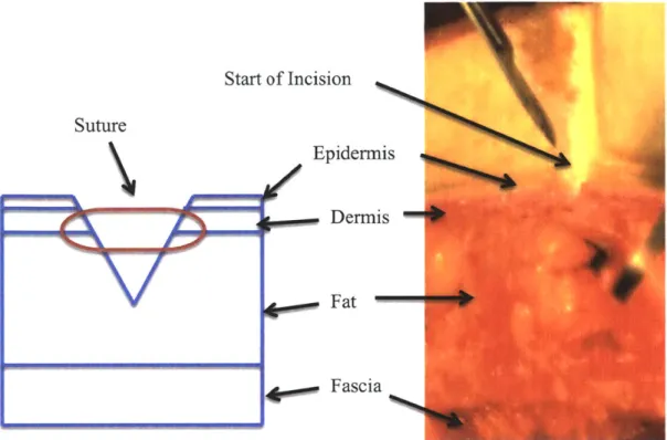
Skin consists of three main layers: the epidermis, dermis, and fascia. The thickness of the uppermost layer of skin, the epidermal layer, is on the order of 100 gm and acts as a protective barrier between the outside world and the body. The layer of skin directly below the epidermal is
called the dermis. The dermal layer is approximately 1 to 3 mm thick, depending on the person and the area of the body, and is considered the strength layer of skin due to one of its main components, collagen [1]. Finally, a layer of connective tissue called the fascia is separated from the dermis by a layer of fat and interfaces with the interior parts of the body.
Start of Incision Suture Epidermis Dermis Fat Fascia
Figure 1.1: Cross-section of wound showing the layers of skin. Left: Model of skin layers and placement of surgical suture. Right: Cross-section of human skin excised from a
patient and used for testing.
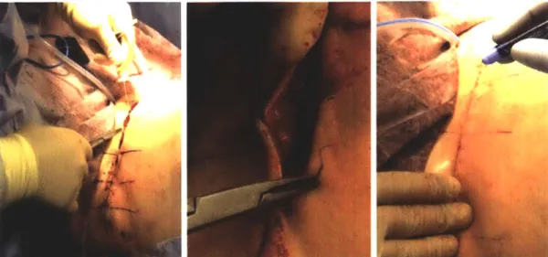
In order to close a long incision a surgeon begins by grossly aligning skin edges with reference
marks and staples, as seen in Figure 1.2. Interrupted sutures are then placed between the staples in the fascia layer for extra closing strength and alignment if needed. The fascia closure is a relatively quick part of the operation because the sutures can be placed every couple inches unlike the dermal closure, which requires sutures approximately every centimeter. Next, the
alignment staples are taken out as interrupted sutures are placed in the dermis. The dermal closure represents about 70-80% of the total wound closure time and is the focus of this project. In some cases it would be sufficient to only close the dermal layer to reduce tension on the wound edges and encourage adequate wound healing. However, for aesthetic appearances, speed of healing, and to reduce the risk of infection, a running suture is often placed in the epidermis to form an everted closely matched skin closure. Finally, a layer of DermabondTM, topical skin adhesive, may be applied on the surface of the closed wound to provide a watertight seal against possible infections.
Figure 1.2: Current wound closing procedure. Left: Gross alignment stitches are placed in the fascia layer. Middle: Interrupted stitch in the dermal layer of skin. Right: Running
suture in the epidermal layer of skin followed by a layer of DermabondTM to form a watertight seal.
1.3 Risks of Conventional Practice
In 2010, over 9 million cosmetic surgical procedures were performed in the United States. Out of those 9 million, breast reductions (135,000) and circumferential body lifts (145,000) are some of the most common that necessitate closing long surgical incisions as described above [2].
Through talks with clinicians in the field of plastic surgery from Massachusetts General Hospital (MGH) in Boston, the approximate procedural times for breast reductions and circumferential body lifts were determined. For breast reductions, the initial incisions and tissue resection takes about 30-60 minutes to complete, while the wound closure can vary between 1.5 and 3 hours. Similarly for abdominoplasty, body lift procedures typically performed on patients with excess skin due to significant weight loss, it takes approximately 1-2 hours to complete skin and soft tissue resection, while more than 3 hours could be spent on wound closure. The significant percentage of total operation time spent on the repetitive rote procedure of closing wounds presents a great opportunity for improvement.
How great is this opportunity? $6.2 billion is spent each year on surgical procedures [3]. With an operating room cost as high as $66 per minute, wound closure could amount to approximately
$6000 per operation or more [4]. Therefore, any time saved during the procedure would reduce
day. Both results could lead to a decrease in costs for the patient and an increase in profits for the hospital. Reducing the wound closure time by 20min in breast reductions and abdominplasty
alone could result in a savings of $370M per year. In addition, less time in the operating room means less time the patient is under anesthesia, which would reduce their risk of stroke, blood
clots, and heart attack during and after the procedure [5].
1.4 Alternative Approaches
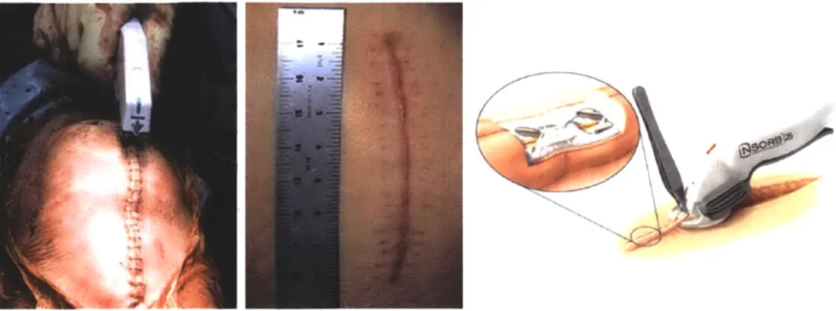
Prior inventions have endeavored to capitalize on this great opportunity and create a superior alternative to manual wound closure, but all have fallen short. The fact that a majority of plastic surgeons continue to hand stitch wounds together is a testament to the failure of previous attempts. Reasons for failure vary among devices, but some of the main issues were ugly scarring, foreign material spitting out of the wound, compromised wound integrity, tedious manual alignment of skin, and a complicated user interface. Surgical staples, for example, may shorten the closure time by 70-80% [6]. They are easily disposable and modestly priced at $10 per device. However for delicate tissues, wounds in finely contoured areas, around bony prominences, and cosmetically sensitive areas, surgeons still suture wounds together by hand. The main reason staples are not used is because they lead to bad scarring caused by less precise skin alignment and the staple legs, as shown in Figure 1.3. This has rendered surgical staples useless for many operations within plastic and reconstructive surgery. Staples are also non-absorbable and require a secondary visit to remove them, which increases the costs associated with the procedure.
'lop
Figure 1.3: Past devices that tried to solve the skin closure problem. Left: Disposable surgical staplers are fast but can only be used on certain parts of the body. Middle: Closing the wound with staples would leave ugly track marked scars due to less precise wound edge
alignment. Right: INSORBTM stapler [71 can place absorbable staples inside of skin but requires special training to correctly grasp skin with forceps and sometimes the staples lose
their strength due to absorption [8].
To address the problem of scarring with surgical staples, Incisive Surgical Inc. (Plymouth, MN)
developed the INSORBTM, a stapler with absorbable clips, for closing the dermal layer. This particular stapler deploys a U-shaped staple composed of a polylactic and polyglycolic copolymer directly into the dermal layer to achieve wound closure. Fick et. al. [9] reported a reduced inflammatory response when using this dermal stapler device in an animal study. Cross et. al. [8] further investigated the utility of INSORBTM in a clinical trial involving eleven patients and reported a closure speed 4 times faster than that of standard suture closure. Despite its fast
speed, the stapler is not very easy to use, and requires training in how to grasp and align the skin with specialized forceps to ensure proper staple positioning. Even though Herridge's study [10] measured hold strength to be 40% around the closure site at 14 days, surgeons have experienced
staples spitting out of the wound or absorbing too fast, resulting in the wound reopening in many cases. The INSORBTM device is also designed to be disposable and costs $45 per unit. However it is important to remember that the cost of materials to close a wound is small when compared to the cost of the time for wound closure. The material cost can be made up in less than 1 minute of
operating time. The real decision that needs to be made is between the cost of operating time and aesthetic outcome. The INSORBTM struggled to succeed because it did not achieve an aesthetic durable wound closure comparable to hand stitching in its quest for the speed of a surgical stapler.
1.5 Overall Project Goal
In order to succeed, the goal is to address the problems associated with available wound closing technologies, and seize the clear opportunity to combine the speed of surgical staplers with the functionality of common absorbable sutures in a rapid skin closure device. The device will attack the most time consuming part of the wound closure process, the dermal closure, in order to close the wound faster than hand stitching, while achieving the same results. If it succeeds, the rapid skin closure device will be adopted, first by plastic surgeons and then general surgeons, as the new standard operating procedure for wound closure.
1.6 Thesis Focus
This thesis focuses on the design, development, and optimization of the actuation mechanisms for the needles, clipping, and alignment parts of the rapid skin closure device. The design and optimization of the actuation mechanisms for this device are critical to its success as a viable mass-produced product capable of revolutionizing the field of wound closure.
The rapid skin closure (RSC) project was developed during the fall semester of 2011 and spring semester 2012 at MIT by a team of five mechanical engineers including myself, and the expertise of two doctors from MGH in Boston. The RSC team designed and manufactured two prototypes each semester for the class 2.75. The prototypes from the fall semester were created to prove the team's design strategy was feasible. The prototypes created in the spring semester improved on the designs from the fall and focused on bringing the device closer to a production ready product. This thesis does not cover the design process for the clip, needle, or loading mechanism unless it directly affects the design or requirements for actuating the desired motions of the device. My main role in the project was the design and development of the actuation mechanisms.
The chapters on prototype development will follow the chronological order the prototypes were designed in, and the beginning of each chapter will contain a preview of the final prototype design discussed in that chapter. After the preview of the prototype, the chapter will examine the development process of the actuation mechanism for the alignment, needles, and clip motions. Possible design solutions will be identified and initial analysis performed to highlight the
strengths and weaknesses before down selecting to a particular design to prototype. The results of the prototype's actuation mechanisms will then be discussed and improvements suggested for the next iteration. Insights regarding possible future developments that are beyond the scope of the project's deadlines and resources will be discussed briefly throughout the thesis and in the concluding chapter.
CHAPTER
2
BACKGROUND
2.1 Wound Closure Strategy
The overall functional requirements and strategy for the rapid skin closure device were developed after two months of research into the mechanics of wound closure, talks with clinicians from MGH, and extensive concept generation. The results of this research produced the following functional requirements summarized in Table 2.1, and the concept strategy depicted in Figure 2.1.
Table 2.1: Rapid Skin Closure Device Functional Requirements
Associated Operating Costs << Hand stitching
Aesthetic Results > Hand stitching
Wound Closure Strength > 28N
Discrete Closure of Dermis Interrupted dermal connections
Operation Speed > 3cm/min (50% faster than hand stitching)
Simplicity No training or postoperative procedures
Revisable Simple to fix errors
Compatible with: straight and curved Flexibility wounds; range of dermis thicknesses and
wound tensions; wound lengths 15-60cm
(1)
(2)
(5)
(6)
Figure 2.2: Project strategy for wound closure in 6 steps.
Strategy steps:
1. The incision viewed as a cross-section. Dermal layer represented by the top layer and the
Fat layer directly below it.
2. Skin alignment component lines up with skin edge and surface.
3. Alignment component actuated to lift skin into pre-determined position.
4. Needles load clip ends and are inserted into the dermal layer of skin following a pre-determined path.
5. Needles come together at 90-degree angle and an ejector pin pushes the clip ends together to form a closed loop.
6. The closed loop clip is left behind in the dermal layer. The clip is absorbable and can be
tensioned similar to a zip-tie by a doctor to create the proper wound tension for minimal scarring.
Due to the compressed time schedule and limited resources for the project a fully adjustable and bio-absorbable clip was not possible to prototype at the desired scale. However, a simple non-adjustable clip was made to function in a similar way to future clip designs, where a male end of a clip would be pushed through a female end of the clip to form a closed loop. A model of the clip can be seen in Figure 2.3.
Figure 2.3 Clip design. Left: Cad model of clip. Right: 5x scale prototype of clip.
The closed loop clip design was created to solve the problem INSORBTM had with the
absorbable staples losing their strength too quickly. The "U" shape of the INSORBTM staple is an open loop structure that will begin to pull apart as the wound puts tension on the ends during the healing process. This problem becomes magnified as the staple becomes absorbed and looses material thickness. A closed structural loop solves this problem because the strength of the material comes from the tensile strength not the bending stiffness.
The ability to adjust the clip in a zip-tie like fashion is another key future design feature for the clip because wound tension can have a significant effect on scarring. Wound tension also varies greatly depending on the type of incision, location on the body, and each patient's personal body type. This makes it difficult to have a single non-adjustable clip that will work in the majority of cases. The adjustable design allows for the flexibility to adapt to different wound tensions, and harness the experience and knowledge of the doctors, who can judge the proper tension needed to ensure healing with minimal scarring.
2.2
Actuating Mechanisms: Requirements and Goals
In order for the device to be successful, the actuation mechanisms need to enable the device to meet its functional requirements from Table 2.1. In addition, there are several goals regarding the
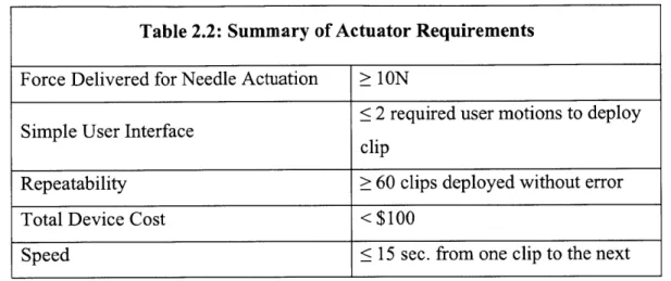
size and complexity of the device that are directly impacted by the design of the actuating mechanisms. Table 2.2 summarizes some of the most important requirements for the actuating mechanisms that will affect the success of the device.
Table 2.2: Summary of Actuator Requirements
Force Delivered for Needle Actuation ;> 1ON
< 2 required user motions to deploy
Simple User Interface ci
clip
Repeatability > 60 clips deployed without error
Total Device Cost < $100
Speed < 15 sec. from one clip to the next
2.2.1 Cost
The cost of the device must be relatively inexpensive compared to the cost saving benefits it delivers by saving operating time. The cost of the device includes material costs, manufacturing costs, and the cost of disposable needle modules for each procedure. The actuating mechanisms for the device will most likely be the main cost-driving factor.
2.2.2 Form Factor
A small form factor that can be mass-produced through methods such as injection molding is
desired because it will reduce costs. If the form is of comparable size to current devices used in the operating room, the device will have a higher chance of being adopted by doctors.
2.2.3 User Interface
Doctors using the device must find it easy to use in comparison to other methods of wound closure. Limiting the number of user inputs required for actuation will make the device simpler to use. A Balanced weight distribution of the actuators within the device will also increase the ease of use and ergonomics.
2.2.4 Force
The actuator must be able to generate the appropriate amount of force to insert needles through the dermal layer of skin. The needle insertion is the greatest force requirement for device at approximately 1ON per needle. [11]
2.2.5 Speed
Fast actuation mechanisms are desired to increase the speed of the device. This is important because the speed of the device will determine the amount of money that can be saved per operation. In addition, the repeatability of the device is important for speed because errors will cause delays. A device that is less sensitive to tolerance errors and performs with high
repeatability will be more reliable, cost effective, and speedy.
2.2.6 Complexity
Simple Actuation Mechanisms that reduce the total part count will make assembly and manufacturing cheaper and faster. A lower part count also reduces the probability of errors, which would affect the speed and accuracy. Reducing the total number of actuators in the device is crucial for lowering the complexity, size, and cost of the device.
CHAPTER
3
Prototype 1
3.1 Development Goals
The design process of the first prototype focused on creating the desired motion for needle insertion in the dermal layer of skin and bringing the ends of a clip together with an ejector pin.
3.2 Prototype 1 Final Design
Figure 3.1 displays the final design of the first prototype, which used multiple cams for the actuation of the needles and ejector pins. Special thanks to Steven Lam for having the initial idea to use slotted paths and rotating cams, and the RSC team for helping build the prototype
Af
a9
Figure 3.1: Final design of Prototype 1. Left: Solid model of Prototype 1. Top Right: Photograph of Prototype 1 without the cams. Bottom Right: Close up of needles coming
3.2.1 Actuation Steps
The description of the actuation motion for Prototype 1 is followed by corresponding figures representing each step.
3 Cams
3 Cam
Followers
Female Ejector Pin Male Ejector Pin
Actuation Bar Actuation Bar
Female EjectoT Pin Needle
-Actuation Bar Female Needle Male Ejector Pin Mc Ne Be; CurvedMale Needle Slot
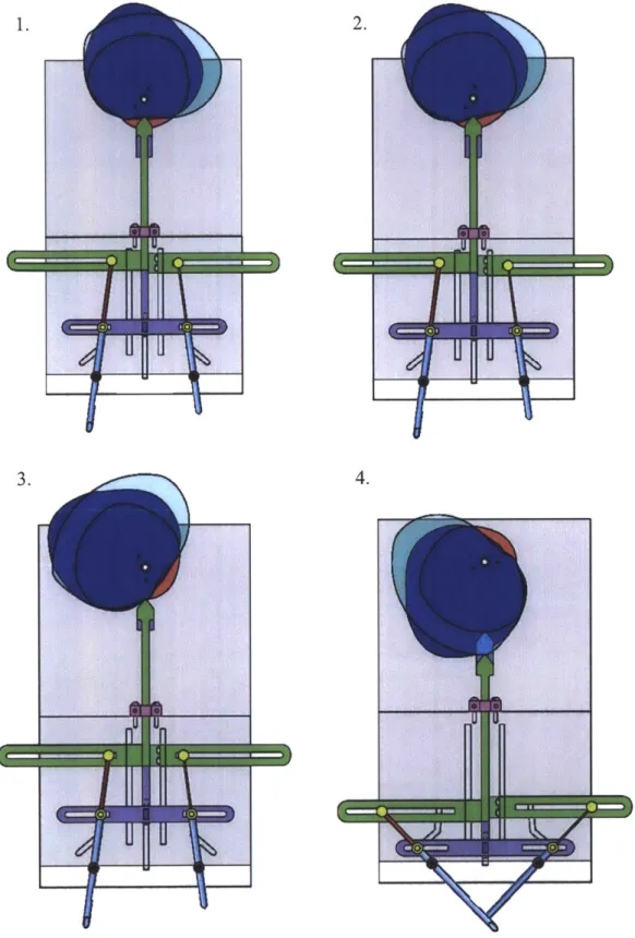
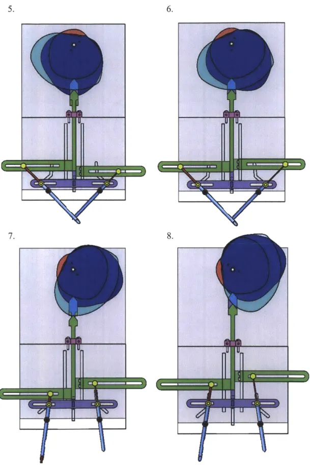
Actuation steps:
1. Starting position for needles and ejector pins. Cams start to rotate counter clockwise.
2. Clips are loaded into the side of the needles during pause in motion created by the rotating cam geometry.
3. The actuation bars for the ejector pins begin to descend vertically driven by separate
cams.
4. The actuation bar for both needles begins to descend in time with the ejector pins. The needle bearings follow a curved slot in the wall to create a straight dermal insertion
followed by a rotation to bring the needle tips together.
5. A cam actuates the right ejector pin in the male needle, while the other components stay
in place during the rotation of the cams. This ejector pin pushes the male end of the clip through the female end of the clip.
6. The male ejector pin retracts.
7. The needles and male ejector pin begin to ascend. The ejector pin in the female needle
stays in place as the needle moves, which causes the clip to be pushed out.
-f----1--4.
I
'Figure 3.3: Prototype 1 actuation steps 1-4. 3.
5.
-
IEGW
7.
I
'Ii
q
Figure 3.4: Prototype 1 actuation steps 5-8.
3.3 Actuator Design
The initial design for the actuation of the needles and ejector pins involved the identification of possible actuators and power transmission elements. These are the building blocks for the mechanism designs. Table 3.1 contains actuators that were selected because their size, weight, cost, and force specifications were within the desired range for the device.
Table 3.1: Actuator Comparison
Strength Weakness
Servo Motor - Compact size * Medium weight
e Low cost, * Linear motion difficult to
- Electrically powered obtain - Precise position control
Pneumatic e Light weight * Requires air supply
Cylinder - Broad range of forces 0 Imprecise position control
e Rotary motion difficult to obtain
Linear actuator e Light weight * High cost
e Precise position control 0 Rotary motion difficult to - Electrically powered obtain
Solenoid - Electrically powered * Heavy for larger throw
lengths
- Imprecise position control - Rotary motion difficult to
obtain
Table 3.2 identifies possible mechanisms to translate the motion of the device.
Table 3.2: Power Transmission Elements
Strength Weakness
Gears - Rotary motion e Requires precise
- Variable timing possible alignment for efficiency - Drive multiple motions
e Allows tradeoffs between torque and speed
Linkages * Rotary and linear motion 0 Fixed length
Bearings e Rotary or sliding motion e Higher cost
e Cam follower
Cams - Complex motions and - Poor efficiency if forces
timing not inline
- Rotary and Linear * Requires precise
motion machining
Cables - Flexible attachment * Elongation from creep
- Rotary and Linear leads to imprecision
motion * Can only pull to actuate
Rotating lead e Rotary to linear motion 0 Requires additional space
screw with - Allows trade offs to constrain properly with
nut follower between torque and bearings
speed - Higher cost
3.3.1 Design Selection
Initial designs of the actuation elements for prototype 1 centered on using a servo powered rotating shaft to drive 3 separate cams. Rotary motion combined with a round cam surface
follower geometry was pressed against the rotating cam surface using springs and was
constrained to travel in the vertical direction. The main cam followers were attached to slotted bars, which acted as cam surfaces for the needle and ejector pin bearings.
The main cam surface allowed for the slotted bars of the followers to be actuated in the vertical direction at different times in order to control movement. The bars for the ejector pin bearings allowed them to slide horizontally as the angle of the needles changed and then actuate the ejector pin in and out of the needle at the appropriate time. Timing is critical between the ejector pin and the needle actuation so that the ejector pin does not push out too soon or not at all. The position of the ejector pin controls the placement of the clip inside the needle.
The actuation bar for the needle bearings also allowed the needle bearings to slide horizontally, during actuation in the vertical direction. The actuation bar's vertical motion was important because it pushed the bearings along a curved path in the case of the device. This path acted as another cam surface that allowed the needles to move linearly during the needle insertion phase and then rotate together for clipping. The curved path designs minimized the amount of required
space for the motion and brought the needles together at a 90-degree angle, which was optimal for reliable alignment of the tip of the needles.
The cam follower method was the simplest way using one actuator to achieve the complex curving motion of the needles with the proper timing of the ejector.
3.4 Results
There were significant jamming problems with the prototype after construction. Ejector pins bent due to bending moments on the small shaft diameter. It was also difficult to rotate cams because forces were not inline with the main cam followers. Finally, the resolution needed for the rotating cam geometry was not met due to the limitations of the water jet used to manufacture them.
3.5 Discussion
The jamming problems were mainly caused by the high friction losses on the multiple cam surfaces due to out of line forces and sliding friction instead of rolling friction. The main rotating cams were large and bulky due to the size required to obtain the necessary motion in a single rotation. The geometry of the cams was optimized for the motion and is unlikely to have a significant size reduction with future development. The millimeter accuracy required for
manufacturing the cams could also lead to higher manufacturing costs. These issues with the cam design led to the decision to search for alternate methods of actuation in the next prototype.
The curved needle paths that direct the needle motion and the vertically actuated slotted bars were worthwhile concepts to keep in the next iteration. However, the ejector pin will need more
CHAPTER
4
PROTOTYPE
2
4.1 Development Goals
The goal for Prototype 2 was to improve upon the design in Prototype 1, evaluate alternate methods for needle and ejector pin motions, and begin development of a skin alignment mechanism and actuation.
4.2 Prototype 2 Final Design
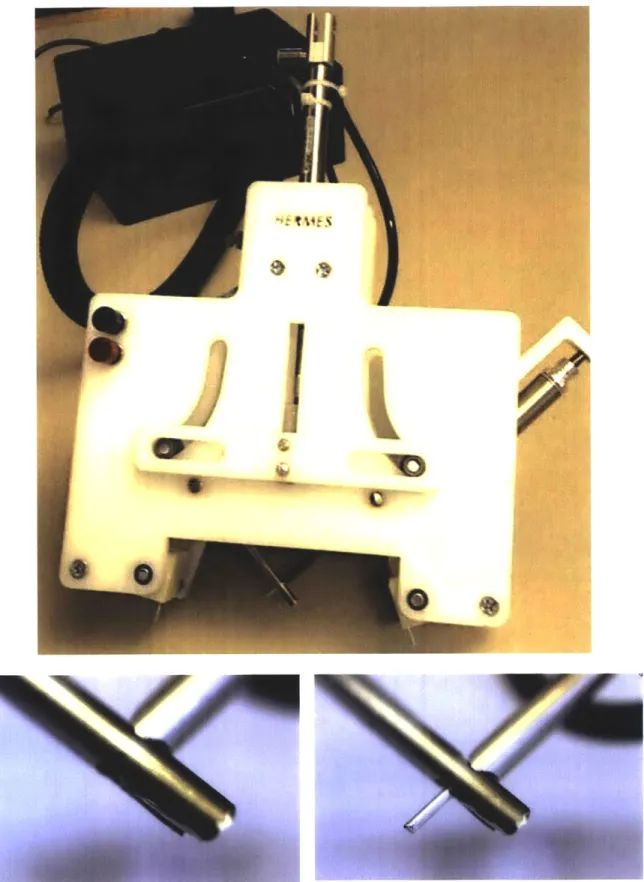
Figure 4.1 displays the final design of Prototype 2, which used three pneumatic cylinders to actuate the alignment, needles, and ejector pin. The alignment mechanism involved vacuum suction to adhere to the skin before rotating into position. Special Thanks to the RSC team for helping build Prototype 2.
Figure 4.1: Pictures of the final Prototype 2 Design. Top: Front of Prototype 2. Bottom: Needle alignment and ejector pin actuation.
4.2.1 Actuation Steps
The description of the actuation motion for Prototype 2 is followed by corresponding figures representing each step.
Ejector Curved Slot ' Female Needle Male Needle
located on back Alignment Pad
of device
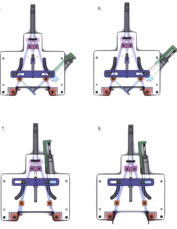
Actuation steps:
1. Starting position. Alignment pads are pressed against the wound edge with the aid of a
torsion spring and adhere to the skin with vacuum suction.
2. A pneumatic cylinder in the rear of the device actuates and pulls two linkages connected to the alignment pads causing them to rotate the skin into position for needle insertion.
3. A second pneumatic cylinder actuates the main slotted bar downward directing the needle
bearing along the curved paths on the front of the device. At this point a clip is loaded through the front of the needles before the needles insert through the dermal layer of skin. 4. The slotted bar continues to drive the needle bearings to the end of the curved paths,
which causes the needles to rotate towards each other and meet at 90-degrees.
5. Throughout the previous movement a third pneumatic cylinder has traveled with the needle bearing and is connected to an ejector pin located in the needle where the male
end of the clip is located. This pneumatic cylinder actuates and drives the ejector pin through the other needle and successfully pushes the male end of the clip through the
female end located in the other needle.
6. The third pneumatic connected to the ejector pin retracts to its initial start position. 7. Next, the slotted bar is actuated upward by the second pneumatic cylinder which returns
the needles to their starting position. The clip pulls out of the female needle during this process because it is rigidly attached to the skin.
8. Finally, the alignment pads lose suction and the pneumatic cylinder releases them so they
v 0 0 0
4.
5. 6.
7. 8.
4.3 Skin Alignment Design
A main focus of Prototype 2 is to develop a strategy that aligns the wound edges consistently and
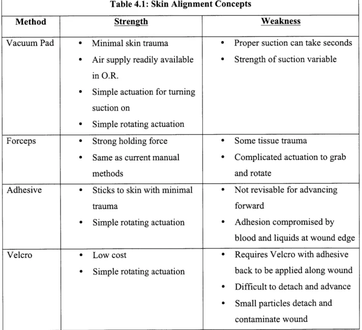
reliably for proper needle insertion. The strategy for aligning skin requires an actuation of some kind to move the skin into position. The basic method that all the designs must accomplish is (i) adhere to a section of skin on each side of the wound and (ii) rotate it into position so that the needles insert the same depth into the dermal layer of skin directly across from each other. Table 4.1 summarizes the strengths and weaknesses of the main alignment concepts that were considered.
Table 4.1: Skin Alignment Concepts
Method Strength Weakness
Vacuum Pad - Minimal skin trauma * Proper suction can take seconds
0 Air supply readily available 0 Strength of suction variable
in O.R.
- Simple actuation for turning suction on
- Simple rotating actuation
Forceps - Strong holding force 0 Some tissue trauma
e Same as current manual Complicated actuation to grab
methods and rotate
Adhesive - Sticks to skin with minimal 0 Not revisable for advancing
trauma forward
- Simple rotating actuation - Adhesion compromised by blood and liquids at wound edge
Velcro - Low cost - Requires Velcro with adhesive
- Simple rotating actuation back to be applied along wound - Difficult to detach and advance - Small particles detach and
4.3.1 Design Selection
Concepts involving Velcro and adhesives were problematic because of wound contamination with Velcro particles and the inability to advance forward with adhesives. These were not issues that would go away with further refinement. This narrowed down the options to the vacuum pad and forceps concepts. For this prototype, the vacuum pads were chosen because they could be actuated with a simpler mechanism. The forceps required a mechanical mechanism for grabbing and rotating, while the vacuum only required a mechanism for rotation. Figure 4.5 shows the final design of the alignment mechanism. Special thanks to Steven Lam for developing the suction pad design.
I I
Figure 4.5: Solid models of suction skin alignment mechanism. Top Left: Suction pad design. Top Right: Rear view of device showing complete actuation design. Bottom: Side
4.3.2 Actuation Steps
Steps:
1. Starting position. Suction pads are rotated outward due to a torsion spring. Vacuum
suction is turned on.
2. The pneumatic actuates a driving bar that pulls the linkages constrained by slots in a vertical direction. The linkages rotate the suction pads in order to hold the skin in the proper position for needle insertion.
3. Vacuum suction is turned off, and the pneumatic lowers the driving bar. The torsion
spring rotates the suction pads back to their start position from step 1.
A
0 0 0M
. 0 I Initial forceFigure 4.6: Suction skin alignment actuation steps.
calculations for the vacuum pressure showed that 185mm}Hg of pressure was required, and further testing showed that 195mmHg was adequate to grab and move the skin.
4.4 Ejector Pin Actuation For Clips
The goal for the ejector pin actuation was to reduce the complexity of the device and find alternative methods to the rotating cams for actuation. To reduce complexity the female ejector pin was eliminated because it was no longer required to eject the connected clip. The clip would slide out of the needle during needle retraction because of its rigid attachment to the wound. The search for alternative actuation methods revealed several key design challenges because the ejector pin motion was no longer precisely controlled with respect to the needles. This was not an issue in prototype 1 because the rotating cams allowed for control over the actuation timing, position of the ejector pins, and the position of the needles. However, these challenges needed to be addressed in order to develop a viable concept. The two main challenges were asynchronous movement and achieving precise ejector pin positions within the needles.
Curved needle paths cause asynchronous movement between the ejector pin bearing and needle bearing. As the needle bearing travels through an arc the ejector bearing must travel a farther
vertical and horizontal distance in order to maintain the same position of the ejector pin within the needle. In order for this to happen, the ejector pin bearing needs to travel at a different
horizontal and vertical speed than the needle bearing. This is because it needs to travel through a longer arc in the same amount of time. Figure 4.7 illustrates this concept.
30 40
In Figure 4.7, the smaller arc represents the path of the needle bearing, and the longer arc represents the path of the ejector pin bearing. In order for them to maintain a constant distance apart through the entire motion, the ejector pin will need to be traveling faster than the needle bearing with the correct timing.
The difference in ejector pin and needle motion presents a problem if there is little control over the timing and speeds of the two bearings, and ejector pins require precise positioning within the needle. If the speeds and timing are off, the ejector pin will move in and out of the needle and potentially push a clip out before it is ready. This creates the challenge of achieving multiple
states of the ejector pin position within the needle through the actuation movement.
The ejector pin position within the needle is critical because it controls the location of the loaded clip. The three required positions are presented in Figure 4.8.
Figure 4.8: Critical ejector pin positions. Left: Initial position of ejector pin when clip is loaded through the side of the needle. Center: After clip is loaded into the needle the ejector pin advances forward a small distance to prevent the clip from falling out the side, but far enough to push the clip out of the needle. Right: Ejector pin pushes the male end of
The spacing is minimized within the needle to reduce the packaging size of the device. This means if the ejector pin is a couple millimeters out of place it is possible for the clip to fall out or fail to connect the male end with the female end of the clip.
These two design challenges become problematic when reviewing the available actuators for the device described in Table 3.1. The challenge of asynchronous movement makes it difficult to have an actuator separated from the needle movement. If the ejector pin actuator is traveling with the needle bearing, then the ejector pin will act as an extension of the needle. The actuator
mounting will provide the appropriate constraints and stiffness for the ejector pin. The need for the actuator to travel with the needle bearing eliminates the solenoid as an actuating mechanism because it will be too heavy. The servomotor is also a poor choice because it delivers rotary motion. It would require additional space and components to convert to the required linear motion of the ejector pin. That leaves pneumatic cylinders and position controlled linear
actuators. In this case, a pneumatic will not work because it can only deliver two end states and 3 controlled states are necessary for the ejector pin. Based off the requirements the only actuator that can meet the design challenges is the position controlled linear actuator. Unfortunately these actuators cost on the order of $100 or more and put the cost of the device above the suggested design requirement.
4.4.1 Reverse "Pen Click" Design
The challenge of achieving 3 precise end states with a cheap and imprecise actuator needed careful thought. In the end, the mechanical click of a pen brought on a spark of creativity. Pen clicks use an imprecise actuation method, a button, to achieve two consistent end states. The motion involves pushing the pen tip to its farthest position so it retracts back to a writing position or inside the case. As the pen is continuously clicked using the same button the end states of the pen tip alternate. Applying the same concept in reverse to the ejector pin, the ejector pin could be pulled back to its farthest position by an imprecise actuator then released to fall into one of its predetermined end states. In this case the ejector pin would have three possible states that it would rotate between instead of the two used by pens. The following figures represent the solid model of the reverse pen click concept and the steps involved in its actuation.
Actuator Lever travels in the vertical direction Needle Bearing Male Needle
Figure 4.9: Annotated model of reverse pen click design. Left: Solid model representation of pen click concept. Right: Concept is comprised of a case, cap, and plunger. The plunger
is pushed up and then released to reach the next state. The cap snaps onto the case and includes geometry to house a spring and facilitate the movement of the plunger.
Actuation steps:
1. The plunger is directly connected to the ejector pin and represents the position of the
ejector pin in the needle. In this position the plunger is resting on a groove in the case, and the ejector pin is in its initial state for the loading of the clip.
2. The plunger is pulled upward by the actuator and hits the angled geometry on the cap.
3. The plunger slides up the angled geometry on the cap
4. The actuator releases the plunger, and the compression spring located within the cap pushes the plunger down on to the angled groove of the case.
5. The plunger slides down the groove.
6. The plunger falls into the groove channel of the case. 7. The plunger slides down the channel.
8. The plunger reaches the bottom of the channel representing state 2 for the ejector pin
position.
9. The plunger is then pulled up again and the motion continues as the ejector moves to state 3, then state 1, and so on.
1.
Figure 4.10: Reverse pen click concept actuation step 1. Left: Inside view of the Case. Right: Step 1.
2. 3.
4. 5.
6.
8. 9.
Figure 4.12: Reverse pen click concept actuation steps 6-9.
The reverse pen click concept was 3D printed due to the complex geometry. The prototype worked as expected, but during the printing phase a design change was made that allowed for a
simpler solution.
4.4.2 Ejector Pin Design Change
The assumption for the ejector pin motion was that the clips would be loaded into the side of the needle. In order to reduce the complexity and have more flexibility in the design, it was decided that the clips could be loaded through the front of the needles. This would expand the length of the needle paths and size of the device but would cut the number of required ejector pin states from three to two.
Figure 4.13: New critical ejector pin positions. Left: State 1 of the ejector pin to allow for clip loading. Position can vary a little but it is desirable to keep the clip towards the front of
the needle so tissue does not clog the needle during skin insertion. Right: State 2 of the ejector pin to push the clip out.
4.4.3 Actuator Design Concepts
The reduction in the number of states for the ejector pin allowed for more flexibility in the design of the ejector pin actuator. Table 4.2 represents the main concept strategies that were thought of.
4.4.4 Design Selection
Based off the strengths and weaknesses from the Table 4.2, the design selection for the ejector pin actuation narrowed down to a pneumatic that traveled with the needles and an ejector pin button hit by a lever. The trade off between the designs is complexity versus space requirement. The button would need to be 3D printed, while the pneumatic was already on hand. The
pneumatic concept was also attractive since pneumatics were already being used for the alignment actuation. All the forces would be inline, which would reduce friction losses in the system and bending moments on the ejector pin. The button concept would be worth pursuing in
Table 4.2: Ejector Pin Actuation Concepts
Method Strength Weakness
Pneumatic actuator - Low complexity e Medium space
travels with needle - Forces inline requirements
bearing - Actuator travels
with needle assembly
Ejector pin aimed at - Actuator not required * Medium complexity needle after motion to travel with needles - Large space
stopped e Forces inline requirements
Lever that pushes a - Actuator not required * Medium complexity simple button attached to travel with needles - Possible friction
to the ejector pin e Small space losses
requirements - Multiple designs to
a future design that tries to optimize the form factor of the device, but for the purpose of the deliverable for this prototype the function was a bigger concern. Since the presentation for the project was in 7 days, the risk of prototyping the button idea was too great, and the decision was made to go with the pneumatic design.
Ejector Pin
/
Pneumatic
Nee
Cylinder
Needle Bearing
Figure 4.14: Pneumatically actuated ejector pin design. Left: Solid model of ejector pin assembly in its first state. Right: The pneumatic cylinder has actuated and pushed the
ejector pin to its second state.
4.5 Needle Actuation
Actuation of the needles in this design will be similar to the actuation in Prototype 1. The needle bearings will follow a curved path in the device case and will be driven by a slotted bar that travels in the vertical direction. The curved paths were optimized from Prototype 1 to reduce friction, create a smaller form factor, and achieve smoother motion.
Figure 4.15: Optimized needle path geometry. Left: Prototype 1 design. Right optimized Prototype 2 design.
Since the timing of the needles is different from the alignment mechanism and ejector pin in this prototype, the needles will require a separate actuator to push the slotted bar up and down. Pneumatics were selected for the actuator to drive the slotted bar because the needles only required an initial state and end state for deployment. Pneumatic cylinders were also being used for the alignment and ejector pin mechanisms, and it would be simpler to control if all the
actuators were the same. In addition, pneumatics are cheap, easy to control, and simple to mount.
There was another small modification with the slotted bar actuating the needles. In prototype 1 the bar supported the bearings on just one side, which caused frictional losses due to forces out of line with the direction of motion. For Prototype 2 it was decided to support the needle bearing on both sides to fix the problem of misaligned forces.
Slotted Actuation Bar Slotted Actuation Bar New Design Walls with slotted needle paths Needle
OOA
NeedleFigure 4.16: Needle bearing supports. Top Left: Solid model of Prototype 1 design with the needle bearing support on just one side. Top right: Solid model of Prototype 2 with the
slotted bar supporting the needle bearing on both sides. Bottom: A close up picture of Prototype 2 that shows the needle bearing supported by the slotted bar.
4.6 Results
Initial alignment testing proved promising. The vacuum pressure from a compressor was strong enough to grab skin and move it around at 195 mmHg. However, it was discovered that vacuum pressure in hospitals only have a high, medium, and low setting that can vary with the weather and from room to room. The unreliability of the proper vacuum pressure would require a compressor or compressed air container to use device. Also, the rotation of the alignment pads
was difficult because the air hoses tended to pinch and close off due to the small space requirements.
Results for the needle and clip actuation were positive. The pneumatically actuated mechanism connected clips reliably over a hundred times in a row and had a 98% success rate over 300 trials. The pneumatic cylinders were controlled through a 2-button user interface, which satisfied the functional requirement of a simple to use device. Unfortunately tests could not be conducted in human skin because needles were prototyped at 5x scale in order to make prototyping easier for the clips and needles.
4.7 Discussion
The problem of unreliable vacuum pressure in the operating room makes the use of pneumatics less desirable. Pneumatic cylinders are also tall because of the required draw length and would be difficult to package into a smaller design. Future designs should attempt to reduce the number of actuators by combining motions and avoid using pneumatics. This will aid in reducing
complexity, size, and cost. It is important to reduce the packaging and size of the device because it is much bigger than most devices found in the O.R. Smaller needles should be made to enable testing in human skin, and the ramifications of smaller needles on the actuating mechanisms
should be considered. Finally, alternate alignment mechanisms that do not rely on vacuum pressure should be developed.
CHAPTER
5
PROTOTYPE
3
5.1 Development Goals
The goal for the semester in which prototype 3 was built, was to refine the rapid skin closure device and bring it close to a production ready product. The specific goals for Prototype 3 were to address the problems with Prototype 2 by reducing the number of actuators, developing a new alignment method, and reducing the overall size of the device.
5.2 Prototype 3 Final Design
The final design of Prototype 3 used passive rail alignment and combined the actuation of the needles with the ejector pin, which allowed for the device to be manually actuated by a handle.
Special thanks to the RSC team for helping build Prototype 3.
Figure 5.2: Solid model of Prototype 3. Top: Front view with the Front wall removed. Bottom: Rear view. Special Thanks to Omar Carrasquillo for helping with the solid
modeling of Prototype 3.
tow MW
5.2.1 Actuation Steps
The description of the actuation motion for Prototype 3 is followed by corresponding figures representing each step.
Upper Actuation Alignment rod
I
Return bolt/
RailFigure 5.3: Annotated model of Prototype 3.
Bar
Actuation steps:
1. Starting position of device. Device has already slid along the rail geometry, which has
rotated the wound edge into the correct position for needle insertion.
2. The upper actuator bar begins to move downward. The clips load into the front of the needles, then the springs between the upper and lower bar compress slightly as the needles insert into the skin along straight paths.
3. The needles come together at 90 degrees. The lower bar hits a ridged stop.
4. The upper continues to move downward compressing the springs and actuating the ejector pin.
5. The upper bar moves upward and the springs relax as the ejector pin is retracted. The upper bar catches on the return bolts and then the upper and lower bar move together back to the initial position in step 1.
2.
3. 4.
5. 6