Publisher’s version / Version de l'éditeur:
ASHRAE Journal, 29, 6, pp. 145-152, 1957-06
READ THESE TERMS AND CONDITIONS CAREFULLY BEFORE USING THIS WEBSITE.
https://nrc-publications.canada.ca/eng/copyright
Vous avez des questions? Nous pouvons vous aider. Pour communiquer directement avec un auteur, consultez la première page de la revue dans laquelle son article a été publié afin de trouver ses coordonnées. Si vous n’arrivez pas à les repérer, communiquez avec nous à PublicationsArchive-ArchivesPublications@nrc-cnrc.gc.ca.
Questions? Contact the NRC Publications Archive team at
PublicationsArchive-ArchivesPublications@nrc-cnrc.gc.ca. If you wish to email the authors directly, please see the first page of the publication for their contact information.
NRC Publications Archive
Archives des publications du CNRC
This publication could be one of several versions: author’s original, accepted manuscript or the publisher’s version. / La version de cette publication peut être l’une des suivantes : la version prépublication de l’auteur, la version acceptée du manuscrit ou la version de l’éditeur.
Access and use of this website and the material on it are subject to the Terms and Conditions set forth at
Thermal performance of frame walls - Part III : Wall Surface
temperatures
Handegord, G. O.
https://publications-cnrc.canada.ca/fra/droits
L’accès à ce site Web et l’utilisation de son contenu sont assujettis aux conditions présentées dans le site LISEZ CES CONDITIONS ATTENTIVEMENT AVANT D’UTILISER CE SITE WEB.
NRC Publications Record / Notice d'Archives des publications de CNRC:
https://nrc-publications.canada.ca/eng/view/object/?id=40a96c19-3db0-45b8-9239-e221b7a85f35 https://publications-cnrc.canada.ca/fra/voir/objet/?id=40a96c19-3db0-45b8-9239-e221b7a85f35
THERMAL PERFORMANCE OF
FRAME WALLS
PART Ill
WALL SURFACE TEMPERATURES
by
G. 0. HANDEGORD
NATIONAL RESEARCH COUNCIL
CANADA
RESEARCH PAPER NO. 34
OF THE
DIVISION
OF BUILDING RESEARCH
REPRINTED FROM
ASHAE JOURNAL SECTION, HEATING, PIPING AIR CONDlTlONlNG JUNE 1957
OTTAWA
HIS publication is being distributed by the Division of Build-
Ting
Research of the National ~ e s e a r c h
Council as a contribu-
tion towards better building in Canada. It should not be repro-
duced in whole or in part, without permission of the original pub-
lisher. The Division would be glad to be of assistance in obtain-
ing such permission.
Publications of the Division of Building Research may be ob-
tained by mailing the appropriate remittance, (a Bank, Express,
or Post Office Money Order or a cheque made payable at par in
Ottawa, to the Receiver General of Canada, credit National Re-
search Council) to the National Research Council, Ottawa.
Stamps are not acceptable.
A
coupon system has been introduced to make payments for
publications relatively simple. Coupons are available in denomi-
nations of 5, 25, and 50 cents, and may be obtained by making a
remittance as indicated above. These coupons may be used for
the purchase of all National Research Council publications in-
cluding specifications of the Canadian Government Specifications
Board.
OReprinted from ASHAE JOIJRPIAL S r r c ~ r o N , H c i r l i ~ g , P i p i n g & A i r Conrli~iot,i~rg, Junc 1957 Printcd In U.S.A.
couples were installed at various lo- cations throughout the wall.
Heat meters were used in most of the tests to determine rates of heat flow into areas over the stud and midway between sludding. These meters were of the multiple differ- ential thermocouple type, with the sensitive elements mounted belween synthetic resin sheets 1ls1/2 in. square. Each meler was held against he wall surface by 4 spring-loaded poly- styrene rods which extended from a carriage that could be moved verti- cally up the wall. The emf generated 1,y the thermopile was recorded for a period of at least 1 hr at each location using an electronic strip chart potentiometer.
A
third heat meter was used in one of the tests to provide a measure of the rate of heat flow into the center of the sheathing al mid-height. This meter was secured to the warm face of the sheathing with1/4
in. No.6 wood screws.
Test Procedure
The same basic wall panel, 8 ft in height by
5
standard s~ucl spaces in width, was used for all Lesls. Thc two outer stud spaces were iilsulated with mineral wool insulation and were left unchanged during all studies. The different lypes of in- sulation tested were installed in the three inner spaces, but all measure- ments were confined to the center space.Modifications to the insulation of the test panel were made prior to weekends with the subsequent test period being of 3 to 4, days duralion the following week. Four complete temperature traverses, and 2 com- plete heat meter traverses were made during this time.
Description of Walls Tested
The basic wall panel consisted oE
6- by %-in. bevel cedar siding as
exterior finish, sheathing paper, 25/32. X 10-in. spruce shiplap sheathing, 2- X 4-in. framing (actual
dimensions 11A2 X
3y2
in.) andv8.
rccLions. The cornrnercial insulations in. gypsum .rvallboarcl. The gypsum s~udied are IICSL illus~ra~erl by ~11e .rvalll~oard was secured to the fram- horizonla1 serliotls sho\vn in Fig. 1.ing xvi111 l-in. NO. 12 \ V O O C ~ S C ~ ~ U S For lurlhcr tesls on i~~sulaliotl GL at
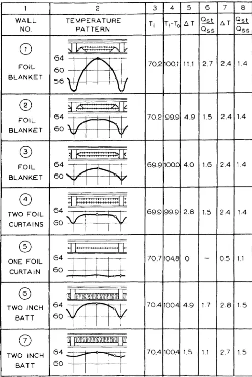
Fig. 1
-
Surface temperatures on frame walls with different types and arrange- ments of insulations ONE F O I L CURTA l N@
TWO INCH B A T T0
TWO INCH B A T Tso tlial it could be removed LO change
the insulation.
Twenty-six different insulalion ar- ra~igernents were tested involving both reflcc~ive and mineral wool types. Six forms of comnlercial house insulation were stuclied and thesc wcre applied as carelully as possible according to the manufacturers' di-
thc stud. a prelormed low-tlcxnsi~y; glass fiberboard-~ypc insulation was cemeutecl to he colcl side lace ol he
p1as~erl)oard and cut L O accommodale
the Iraming. The insulation and plaslerboarcl were hen removetl as a unil ant1 he insula~ion edges re- cut to ~ h c recluirerl shape at the s l u d d i ~ ~ g for each succeeding test.
3EEzzzE
7
'
2
z:
g m
Heating, Piping & Air Conditioning, June 1957
7 0 4 1 0 0 4 7 0 7 1 0 4 8 7 0 4 1 0 0 4 4 9 0 1 5
-
1 7 1 1 0 5 2 8 2 7 1 1 1 5 1 5Discussion of Results diliolis occurred for walls Nos. 5 ancl
~ ~ l/ ~J ~~ f~o/ iD,'nererLl / ~ ~ ~ ~ 9. where lhc inside-lo-outside air ~ ~ , ~ ~ ~ ~ ~ / J L S I L / ( L ~ ~ O ~ L S : Fig. 1 prol ides 3 sum- 1ernl)erature differences were 104.8 marp of the ~ e s u l t s obtained on 11 F and 98.3 F, respectively. T h e av-
Pig. 1 (continued)
-
Surface temperatures on frame walls with different types and arrangements of insulationsW A L L
N 0.
wall construc~ions having diflerenl lypes and arrangemenls of insul a 1' 1011. The values lislecl represent he av- cragc of measurements taken a t the
2-, 4-, and 6-It levels on each wall. Column 2 shows the cross-seclional clelails o l each panel logelher with he associaled horizontal surlace tem- pcralure paLterrl. The plolted curves are hasccl on rcadings taken over one- hall 111e slud spacc w i c l ~ l ~ . Symmetry TEMPERATURE
PATTERN
has becn assumcd in eslending the c u r l e lor ~ h c width shown.
All pancls Iterc leslccl under simi- lar conclilions with warm-side air
Ti
ancl cold-side a i r lernpcra~ures at ap- prosimately - 3 0 F. The ~varm-sick air lcmperalurcs arc lislcd for each wall conslruction ill Column 3 ancl
T,-To
he insicle-LO-outsiclc ai r tempcralure difference is shown in Column 4. The
erage differences in surface tempcr- alure belween sluclcling and over 111e slud a r e lisled in Column 5 a n d he
ralio helween the rate of heat flow in10 the area over studding to that midway between studs is shown in Column 6.
Wall No. 5 , i n which the insula- A T
lion consis~ed of 2 a i r spaces each faced one side wilh loil had the most uniform wall surlace tempera- lure paltern of a n y of the walls lesled. This wall represents a case where he lhermal resis~ancc of the porlion helween studding is similar
LO that at he sluds, and a close ap-
proximalion LO a lhermally homo-
geneous wall resulls. In regions of scvere winler climate, however, the ~ h e r m a l resistance provided b y such a wall construction is inadequate Irom he economic standpoint a n d is substandard in regard to optimum
Q s t - Qss
grealest deparlure lrom lhc test eon- interior comfort.
Of the walls in which reflective insulation w a s used wall No. 1
showed the greatest horizontal vari- ation in surface temperature. In this wall the insulation provided in the slud space was basically 3 a i r spaces, 2 faced 1 side and 1 faced 2 sides wilh aluminum foil. I n this respect, the insulation was equivalent to that in walls Nos. 2, 3, a n d
4#,
b u t these walls showed less severe variations in surface temperature.Examination of the cross-sectional details for these 4, walls shows that
his improvement in surface tempera- ture pattern is at least partially as- socialed with the degree of exposure of the sides of the studding. I n wall No. 1 he stud was exposed to the cold outer a i r space for its entire depth; in wall No. 2, for two-thirds of its depth; i n wall No. 3, for half its depth, a n d i n wall No. 4 only one third of the side of the stud was so exposed. T h e reflective properties of the insulation tab in walls Nos. 2 a n d 3 would also tend to increase the surface temperature difference by clecreasing t h e lateral flow of heat into the sides of the stud f r o m the warm-side a i r space.
T h e effect of insulation location may also b e noted from a compari- son of walls Nos. 6 a n d 7, where identical batt type insulation was in- stalled. T h e outer portions of the studs i n wall No. 6 were exposed to [he low a i r temperature of the space, while i n wall No. 7 the entire stud was i n a region of much higher tem- perature. T h e lateral heat flow from [he sides of the stud in wall No. 6 and the rate of heat flow into the face of the stucl would b e greater, with a consequent lowering of sur- lace Lemperature over the stud.
Wall No. 8 was essentially the same as wall No. 7, except that a slightly thicker and more uniform mineral fiber insulation was installed. It is included for comparison with wall No. 9 to illustrate the effect of increasing the thickness of insula- tion in the stud space. A s can be A T
Heating, Piping Sr Air C o n d i ~ i o n i n ~ , June 1957
Q s t -
noled, increasing the ~ h e r m a l resist- ance of the slucl space will lend to incrcasc surface temperalure differ- ence. T a l l No. 1 0 is a furlher e s - ample of lhis effect.
The malked influence of lateral heal flolv on surface ~emperaturc pat- lerrl is again apparent from the rc- s u l k for wall No. 11. This reprcscnts an example of poor insulation appli- calion and will be discussecl laler. 11 is included here as a case of ex- lreme horizonla1 surface temperalure cliff erence.
C o m ~ a r i s o n of the resulk presenled in Fig. 1 indicates thal the laleral flow of heat within frame walls may have an appreciable effecl on the warm-side surface temperature pal- tern. The location of semi-thick in- sulalion w i ~ h i n he wall has a marked effect on surlace temperalure as does the fit between the insulation and studding.
Certain general principles of frame wall design for uniformity of surface temperature are suggested b y ~ h e s e results. Specifically, semi-thick batt or blanket insulalions should b e installed as close to the cold side of the space as practicable aiid should provide maximum thermal prolec- lion LO the sides of the studding.
Since liorizontal surface Lcmpera- lure graclienls have implications wilh regard to the occurrence of boll1 dusl palterns and condensation on inside surfaces, the assessment of walls wilh respect to these gradients is highly clesirable. Limiting c r i ~ e r i a for surface temperature difference with regard L O dusl marking have
been suggesled by some aulhorilies'," and have been applied to building regulations."
E v c ~ l r ~ a ~ i o r ~ of JVall Sr~rface Tern- peralrrre Differer~ces: T h e most cli- recl way of delermining wall surface temperatures is b y aclual lesling, but
he cosl of such testing for the va- riety of constructions possible is pro- hibitive. Rigorous malhemalical anal- ysis, on the olher hand, is dificult if nol impossible because of the ex-
lren~ely complex r ~ a l u r e of lhc heat How pallerl~. H o l v e ~ cr, for cci laill Ly11c~ of ~vall co~~slruclions; calcula- tions on the assump~ion o t parallel heal flolv palhs may give reasonably accurale results.
Thc sulfate temperalure difference and ralio of heal flow in a l Lhc stud to that midway bell\ een s~uddirlg, calculated on the assumplion of p a r - allel palhs for the 1~alls in Fig. 1.
a l e listed in Columns 7 and 8. These
is placrd a1 lhc oulsitlc, and in Fig. 2 ( L ) a l t l ~ e insidc, of he space.
\\ ill1 insulalior~ a1 lhc ~ c n l c ~ o f lhc ail space [Fig. 2 ( a )
1
[lie t a n - pclalule levcls imposed on lie sides of the stucl a l e such that the latela1 flolv of heal into the slud near tlze walni s ~ d e i j balanced b y the lalclal loss near lie cold side. The laic of 11cdl flow into ~ h c S L L I ~ will thclcfolca p p l o a ~ h 111al for a cor~dilion of I I O
lalcial heal exchange.
Fig. 2
-
Calculated temperature gradients through a frame wall with different loca- tions of insulationvalues were determined or1 he basis of dala given i n
THE GUIDE
of ASHAE.Ilc~asonably close agreenienl be- ~ ~ v e c n calculaled and observed values of surface temperalure difFercnccs and lieat flow ralios may be noted f o r ~valls Nos. '4, 5, ancl 10. Exami- nalion of thc cross-seclional delails of 111cse walls will show hat, in each case, the insulalion was of uniform ~hickness across 111e enlire width ol
he stud space and was symmetrical- ly placed i n relalion to a plane par- allel LO the wall at he center of the
a i r space. I n these 2 respecls they differed from thc other walls ~ e s l e d .
This agreement between calculaled - and observed values may be partial- ly explained b y Lcnlpcraturc gradi- ents s h o ~ v n in Fig. 2. 111 Fig. 2 ( a )
he calculaled ~ e m p e r a ~ u r e gradienls lhrough he stud ancl through the stud space are sholv~i superimposed
for a frame wall will1 irlsulalioil lo- caled at ~ l i c center ol the a i r space. I n Fig. 2 ( b ) he same insulalion
Localion of insulation as ill Fig.
2 ( 6 ) nil1 expose he sides of t h e slud L O a higher t e m p c r a t u ~ e ieginzc
mlcl die additional laleral heal gain will reduce he rate of heat flo~v into he face of the stud. T h e resultant surface telnperalule over thc face of ~ h c slucl will ~ h u s be higher lliarl lhat calcula~ecl by simple thcory, as il was for wall No. 7.
T h c oppositc condilion will occur wilh insulalion located as sliolvii i n Fig. 2 ( c ) : he sides o l llle stud will b e exposed LO a lolver l c ~ e l of ~ c r n -
p e r a l u ~ e. incleased heal loss horn he
sides of the stud will occur. ancl a lowcr surIace temperalure than lhal ~xcdictecl will r e s u l ~ . T h i s corldilio~l is esenlplificd by thc resulk for wall KO. 6.
'The inlerior and exlcrior cladding ~ n a l e r i a l s of this xvall seclioti have bcrn assurnccl LO posscss ideulical
~ h c l m a l char aclcrislics. This is not slriclly Lruc for ~ h c ~ \ a l l s lrstecl. b u l 111c s a m r general rclaliouship be-
L V ecn Lcmpcralure gradicnls 11 oulcl
exist. This simple analysis, when consiclered villi llic test rcsulls, ~ \ o ~ ~ l c l il~dicalc ~ l ~ a l r e a s o n a l ~ l ~ ac- curale values of surface tcinperaturc difference for frame walls wit11 plas- ter finish may be calculatecl 011 tlie
assumption of parallel heat pallis ~ v h e n insulaliorl is installecl at ap-
rclucscnts a maximum, ancl proviclccl this cloes not cxceed thc accepled criterion, 111c uall may be rcgardecl as acceplal~le.
The assessment of walls ill ~vhich frame constructiou; thc mob1 uidely tlie insulation is ins~allecl in the used insulalion is of ~11e n~i~lercll wool walm sicle of the space is more clif- or glass fiber ball Lype. omin in ally
ficull, fiist l~ccause a limit cannol 2 in. thick. The most common wall
I I 0 1 00 l A 90
w
8 0 Wy
7 0 IX W LL L L 6 0 a' P 5 0rr
a 40 WG2
3 0 3 0 20 W np
l o
-
0 0 I 2 3 4 5SURFACE TEMP. DIFFERENCE D E e F
proximately the center of thc air
space of ~ h c wall ancl 1vhe11 thc in- sulalion is of uniform thickness across the ~vicllh of the slut1 space.
Thc calculation of surface Lemper- alure difference using the foregoing proceclurc may also be employed as a basis for qualilali~e assesslncnl of walls in which the insulaliou is in- slallecl in he cold sicle of he space. Thc c a l c ~ ~ l a ~ e c l x a l ~ ~ c in such cases
-
SERIES I
6
#--*
HEAT FLOW INTO STUD SPACE1
(
I
SURFACE TEMP. DIFFERENCE DEGREE F.I
I
0 1 . oCROSS
-
SECTIONAL AREA OF GAP w t sq. in.Fig. 3 [left)
-
Surface temperature difference as related to overall air temperature differenceFig. 4 [right)
-
Surface temperature difference and heat flow rate as related to insulation shape-
Series Ibc cslablishcd by simple compula- tion, a ~ i d seco~lclly because the shape ol he i~lsulalion at the slud has a marked influence on the surface tem- pcralurc pa~tcrn. For a specific type of wall conslruclion and insulaliori, holvclcr, ~ c s t dala may be used as a 1)asis for assessmenl, or at leas1 for cl aluation of limiling conditions.
The majorily of houses in F ~ c s t e r n Canacla are of reasonably slanclarcl
coiistruclion is of 111c lype shoun for wall NO. 6 in Fig. 1. Thc maximum suiface tempeiatu~e cliflerencc to be cxpec~ed wilh %in. bat1 insulation may, ~hcrefore. be assuinctl as 4.5
1:
when tlic inside-to-ou~siclc teinpcra- Lure clifferencc is 100 F. pio~icled ~ h c insulalion is of u ~ ~ i f o r m thick- iicss a c ~ o s s 111c stud space. For walls ,\ill1 his type of insula~ion installed b c ~ \ \ c c n Lllis posilion the centerof the a i r space a value may b e assumed as between he limils of 4.5
F
and the calculated value of 2.8 F, under the same ambient con-Insulatiol~ Fit at Studding: Thesc p~.oceclul-es lor calculaling wall sur- lace temperatures are dependent on
he insulation being of constanl thickness across the enlire width of the stucl space. Many balt ancl blank- ct type insulations do no1 have a ~ r u l y reclangular edge profile, a n d
SERIES 11
HEAT FLOW INTO STUD
2 0 18 16 14 12 10 8 6 4 2 0 12 10 8 6 4 2 0 0 0.5 1.0 1.5 2 .O
CROSS
-
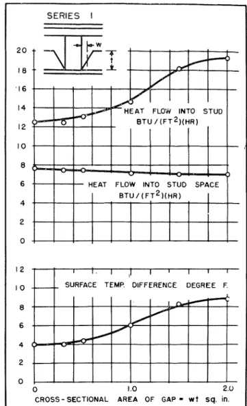
SECTIONAL AREA OF G A P = w(t- b) Sq. in.Fig. 5
-
Surface temperature difference as related to insulation shape-
Series I Iditions. When the design tempera- ture difference is other than 100
F
proportionality may be assumed. This assumption of proportionality is inherent in the calculation ~ r o c e d - ure and is reasonably corrccl for walls such as No. 6, as shown b y the lest results in Fig. 3. T h e plolled ~ o i n t s were obtaincd for wall No. G
at different inside-to-outside air tem- perature differences ranging from 1 0
F
to 1 0 4F.
and heat flow rate
ings \\liich were gicalei. ~ h a n 1G1h
ill.''
To claluate he rclatioiisl~ip bc- L~tecn insulation fit at sludcling and surface tempcralure v a ~ i a t i o n . three selies 01 Lesls u e l e conduclcd using a unifoim. l i g h ~ densily. g l ~ s fiber insulalion. 2 in. thick. which 1) as
10 HEAT FLOW INTO STUD SPACE
8
6
4
2
0 0.5 1 .O 1.5 2 .O 2.5
CROSS-SECTIONAL AREA OF G A P - w t Sq. in.
Fig. 6
-
Surface tcmperuture diCieience and heat flow rate as related to insulation shape-
Series 111in somc cases may have a cross-sec- Lion approaching that of ~ l l c reflec- tive insulation i n wall No. 1. Also the spacing o i studding in actual construclion does not always coin- cide with the 1G-inch module, ancl ill some cases a condilion analogous
L O lhat o i \$all No. 11 may occur. A
survey of houscs in Canadian cilies in 1951 inclicatecl that 5 percenl of
he wall area, exclusive of winclo~v a n d door openings, had stucl spac-
cul to pro\ide varying cleglees 01
c s p o s ~ ~ i ~ e of lie s~ucl. T h e main pur- pose of this s~ucly was to prolicle n
basis f o r rating bat1 insulalions i n rcgarcl Lo surIace tcmperaturr pal- terns i n Lcrins oI their measured pro- file. ~villloul rccourse Lo actual Lrst- ill$.
Thc rcsults of thesc 3 scries 01
Lests a r e sholin in Figs. 4, 5 ancl 6 ,
in avllich tlic cliffcrencc in surIace Lcmpcralure I)cl\vccn locations oVc1. ~ h c s~udcling arid betwcen studding is agairlst the cross-scclional Heating, Piping S: A i r Corlditiolling, Jurie 1957
area
01
the space I ~ e l u e e n insulation and s ~ u d . Coriesponcling ralcs of hral flow inlo ~ h c area ol cr s ~ ~ ~ c l c l i n g and bet~veen sludding a l e also sho~vlii n these fignrcs. ancl in Fig. 5 the rale
01
heat flow through 11112 shealh- ing a1 mid-height 01 the wall is in- cluded. The c o n d i ~ i o ~ ~ s01
Lesl weresulalion and studding is most clitical in the range lrom l/L-in. Lo yL-in., as irlclica~cd by he shape of the curl es for ~ e n ~ p e r a ~ u r e difference ancl heat flo~v into studding. I t will be notcd that the rate of heat flow inlo the crnler
01
the slud space dc- creased slightly will1 increasing slud3. 2.5 2.
I
9
5
1.5 t- U2
W a Q I V, I. 0.5 0 0 1 2 3 4 5 6 7 8 9 1 0 1 1 SURFACE TEMP, DIFFERENCEFig. 7
-
Surface tem- perature difference (in percent of inside to out- side temperature differ- ence) as related to shape factor for frame walls with nominal 2-in. batt insulationiden~ical in all cases, warm-side air Lcmperalnres being maintainecl at a p ~ ~ r o x i i n a ~ c l y 7 0 F, wit11 cold-side air temperatures at approximalely -30 F. Tlle plo~led poiills represent avcrage v a l u c takcil at he 2-: il-
a:~tl 6-11. lel-els: cxccpt lor the heat flow ~lirough 111e s h c a ~ h i n g i n Fig.
5.
Thc cfl'cct of chamfcrring the in- sulalion at various angles lo lhc stucl is slrolvn by thc rrsults of Series I
~ c s t s i n Fig. 4. Apparcnlly the avcr- age width of the space between in-
exposure. This clccreasc was no doubt due to the increase in temper- alnrc
01
he a i r space brought about by increased lateral heat flow iron]he studs.
T h e results of chamlerring the in- sulation at 45 dcg LO the stud LO pro-
vide tlifferent widths of stucl expos- ure a r c sho~vn b y the Scrics I1 tests in Fig. 5. The shape 01 he temper- alurc difl'erence ancl heat flow curves in this figure a r e different from those of Scries I, the rate of change of surface temperature difference in-
creasing with increasing cross-sec- tional area
01
gap. T h e extreme case in Serics I1 was identical to that of SeriesI
a n d reasonably close agree- ment bel~veen results was obtained. F o r all praclical purposes a mean lemperature curve for the results of both Series I and Series I1 might be employed since the individual ex- perimental points would fall within1
F
of such a curve.Further evidence of t h e lateral flow of heat from studding to the air space ancl through the sheathing is provided by the heat flow measure- ments of Fig. 5. T h e rate of heat flow into the wall between studs de- creased, while the rate of heat floxv ~ h r o u g h he sheating increased with increasing stud exposure.
T h e insulalion cross-sections of Series I ant1 I1 approximate the gen- eral shape of some batt a n d blanket insulations as installed i n framing which is spaced at 1 6 in. o r less on centers. Occasionally, however, stud spacings in practice exceed this modular value a n d such situations must be recognized i n the assessment
01
this type of insulation.Series I11 Lests were undertaken to o b ~ a i n some additional information on he surface temperature patterns with oversize slud spacing. Ralher ~ h a n change the width of stud space, ho~vcver, the insulalion was reduced in width Lo provide gaps between insulation a n d studding u p to
lqk
in. The results of these tests are shown in Fig. 6.I t was hoped initially t h a t a simple correlation miglit be obtained for all
3 series of tesls bet~veen th e horizon- tal surface temperature difference ancl the cross-sec~ional a r e a
01
the space between insula~ion a n d stud- ding. This was the case in Series Iand 11. bul no1 in Serics 111, where a s P c ~ i o n of the plaslerboard was also rxposeecl to the cold air space. As- suming this faclor to bc the signifi- can1 difference belween Series I11
and the other two, a n arbitrary shape
factor was used to provide a n empiri-
cal correlation hetween the results of the three serics of tests. This shape lactor was calculatetl as follolvs:
SAnpc f ( ~ c ~ o r = (aterage tl~ickness -
thickness at stl~d) (average width of space
+
~ v i d t l ~ of space at plaster).Using thc terminology of the clia- grams i n Figs. 4, 5 ancl 6,
Shnpc fnctor = ( t - b ) (zu -I- a ) .
T h e results of Series I , I1 and I11 a r c rcplottecl in Fig. 7 with tlie shape lactor as ordinate a u d with the liori- zor~tal temperature cliffercnce ex-
pressed a s a preccntagc of insiclc-to- oirtsiclc a i r temperature cliflercnce as at)scissa. I t is suggcslecl that this relationship may be used to e l a l u - ale halt-type insulalions in rcgarcl to horizontal surfacc tcmperatuie p a t ~ c n l s l ~ y measurement of their lxofilcs a s installed in a mock-up wall. T h e test results were oblainetl for a n i~~sicle-lo-oulsicle a i r t c m p e ~ a - Lure cliffcrcnce of 1 0 0 clrg F, but, l o r practical ~ L I ~ ~ O S C S , t l ~ c curve gi.i ell in Fig. 7 may 1)r employed lor otlicl. conclitions if n linear iclatio:isliip is assumed Lelwcel~ hori7ontal surfacc tc111lx1 ;ILLII t, dilrel C I I C C nrld ir~sidc-to-
outsitle a i r tempcrattllc clilrc~cnc-c. T l ~ i s asstlmpliou has bee11 sliolvri lo f ~ c c o r ~ c c t 101 l ~ a l l s such as No. 6.
I n some cnsrs t h r a l r r a g c 1hic.k- 11c.s of the i n s u l u ~ i o ~ i 1)atl may IIC
grcatcr or 1css tila11 thc nominal 2 in.
An irlcrcase i n batt thickness will tcrlcl to raise thc su11:lce l e m p c r a h ~ r c between s t ~ ~ c l d i u g ancl a t t11c same
tilne will lower the temperature of thc a i r spacc, thus tencling to i n -
crease the latrral heat loss Iron1 the studs. I t is reasonablc to assumc, thcrrlore, that a n increase in halt tliickr~css TI ill incrcasc the surface
temperature clifference ancl this will he accountrcl for qualitatively i n the calculation of shape lactor.
1. Horizontal surface temperature patterns exhibited by f r a m e ~v;llls a r e grcatly inflnenced by the position of tlie i ~ ~ s u l a t i o r ~ within tlie wall a n d by tlie degree of exposnre of stndcling to the ail. in tlie ~ 1 1 1 c;t\ity.
2. When s e m i - t l ~ i r k 11;ttt 01. blanket
insulations a r e e~~iployecl, IIIOI-C ~ u ~ i -
for111 1iori~oiit;tl snl,f;tce teniper.atures a r e ol,t;~ined wit11 tlie i n s n l a t i o l ~ in- stalled 21s cloze t o the cold sitle of tlie space ;IS possible.
3. It is 111ost clesii~a1)lc fro111 t h e stzu~clpoiiit of r i i i i ~ i i ~ ~ u i i ~ 110riz0~1ti11 surface ten~pei.atui*e vsi.intiol~ that seini-thick I ~ a t t o r blanket insulations ~ v l ~ i c l l a r e to 11e located to\vai.d the ~ v ; ~ r i i ~ side of tlie air space provide protection corresponding to a su!)- stantial proportion of their t l ~ i c k i ~ e s s at tlie studding.
4. Calculation of surface teinperil- t n r e differences o n f r a m e ~ v ; ~ l l s o n tlie a s s u ~ n p ~ i o n of parallel heat flo~v paths nlay provide reaso~ia!~ly nccu- r a t e values provideel tlie insulntion is of mif form tl~ickness fl.0111 stud to stnd ant1 is approxi~nately centered in t h e confines of t h e space.
5. \Y'11en tlie ins111atio11 is placecl toward the outsitle of tlie stud spacc calculation of surface tenlperatllres o n the a s s ~ ~ n i p t i o n of parallel heat tlolv paths results in h i p l ~ e r vi~lues of surface teliiperat~lre differei~ce ~ I I L I I I
actually occnr.
6. W l ~ e n the i ~ ~ s n l a t i o n is placed in t h e warm side of the stud space adjn- cent to t h e inside linisl~, calcl~latecl valnes of the difference i n surface temperatures over and betweei~ studs a r e s u l ~ s t : ~ n t i n l l ~ lcss tlian actually oc-
cur. T h e fit of t h e insulations at t h e stnd llils il liiarked effect on the snr-
face telnper:rtlue pilttern. Data a r e presented xvhich permit tlie preclictioii of hoi.izont;~l s n r f ; ~ c e temperntui3e dif- ference f o r batt alicl blariket insnla- tions taking into account tlie s11npe of ;lie insnlatioii in the vicinity of t l ~ e stud.
The author wishes to a c k n o ~ v l c c l ~ e with thanks the assistance of D.
G.
Cole i n the taking a n d recorclir~g o l the data used ill this study. Tllc com- ments ancl suggestions of Dr.
N.
B.
Hutcheon and otlirr mcmhcrs o l the staff of thc Division of Building Research, Olla~va, a r e also greatly apprecia~ecl. This papcr i s a contribu- ti011 f r o m the Division of Building Research, National Rcsemcli Council o l Canacla, a ~ l d is published with t h c approval of ~ h c clireclor.
References
1. Tl~ermal Performance of Frame Walls, by G. 0. I-Iandegord and N. B.
IIntcheon (ASI-IVE Tni\issac~~oxs, Vol. 58, 1952, p. 171).
2. Thermal Performance of Frame
Walls, Part I1 - Air Spaccs Illocked at Mid-IIeight, I)y G. 0. 1-Iarldegord nr~tl
N. I3. FIutcl~eon (ASFIVE 'l'n.\xs:tc~~or\'s,
Vol. 59, 1953, p. 1149).
3. Dirt Patterns on Walls, I)y Il. A.
Nielsen (ASIIVE TIIANS:\(:TIONS, Vol. 46,
1940, p. 2.17).
4.. l)csign of Insulatetl Blliltlirtgs Tor Varions Climates, 11y 1'. S. Rogers (F. \V.
Dodgc Corp., 1951, p. 29).
5. Thermal Properties of B ~ ~ i l d i n ~ s , by
N. S. 13illir1~to11 (Cleaver-1Iouse I'rcss, Lttl., 1952, 11. 103).
6. Stud Spacil~g in Canadian Fraorc Ilouses, by D. I-I. Ilutherford (Jounsar. RAIC, Vol. 30, No. 8, 1953, p. 213).
A list of publications issued by the Division of Building Research can be obtained on application to the Publications Section, Division of Building Research, National Research Council, Ottawa, Canada.