Publisher’s version / Version de l'éditeur:
Vous avez des questions? Nous pouvons vous aider. Pour communiquer directement avec un auteur, consultez la première page de la revue dans laquelle son article a été publié afin de trouver ses coordonnées. Si vous n’arrivez pas à les repérer, communiquez avec nous à PublicationsArchive-ArchivesPublications@nrc-cnrc.gc.ca.
Questions? Contact the NRC Publications Archive team at
PublicationsArchive-ArchivesPublications@nrc-cnrc.gc.ca. If you wish to email the authors directly, please see the first page of the publication for their contact information.
https://publications-cnrc.canada.ca/fra/droits
L’accès à ce site Web et l’utilisation de son contenu sont assujettis aux conditions présentées dans le site LISEZ CES CONDITIONS ATTENTIVEMENT AVANT D’UTILISER CE SITE WEB.
Internal Report (National Research Council of Canada. Institute for Research in Construction), 1993-06
READ THESE TERMS AND CONDITIONS CAREFULLY BEFORE USING THIS WEBSITE.
https://nrc-publications.canada.ca/eng/copyright
NRC Publications Archive Record / Notice des Archives des publications du CNRC :
https://nrc-publications.canada.ca/eng/view/object/?id=2f95ed15-9c7f-4f6c-aa14-835f503bf39d https://publications-cnrc.canada.ca/fra/voir/objet/?id=2f95ed15-9c7f-4f6c-aa14-835f503bf39d
NRC Publications Archive
Archives des publications du CNRC
For the publisher’s version, please access the DOI link below./ Pour consulter la version de l’éditeur, utilisez le lien DOI ci-dessous.
https://doi.org/10.4224/20358907
Access and use of this website and the material on it are subject to the Terms and Conditions set forth at Results of Lift Tests Conducted on ASTM Round Robin Materials Sumathipala, K.; Monette, R. C.
Nationai Research Conseil national Council Canada de recherches Canada
liite+rtiai rE"PyI;
.
I r , s ~ L ? x ~ ~ i + J eInstitute for lnstiiut de >, zq .\' ..'CE
- j*, ,- L-?- -
Research in recherche en -- se,G. C r e i g h t o t l Construction construction
Results of Lift Tests
Conducted on ASTM
Round Robin Materials
by Kuma Sumathipala and Roch Monette
Internal Report No. 645
Date of issue: June 1993
Thls IS an Internal report of the lnst~tute for Research In Construction Altnough no1 Intended for general dlstr~but~on. ~t may be clted as a reference In other publlcat~ons
RESULTS OF LIFT TESTS CONDUCTED ON ASTM
ROUND ROBIN MATERIALS
Kuma
Sumathipala and Roch MonetteABSTRACT
Results from six ASTM round Robin materials are presented. The tests were performed in accordance with ASTM E1321-90. The six materials are: plywood, FR
plywood, polystyrene foam, polyurethane foam, gypsum wallboard, and composite board. The plywood performed predictably in both ignition and flame spread tests. FR
plywood exhibited inconsistent behavior in both tests. Polystyrene foam melted and was accumulated in the specimen holder before flame attachment commenced. Polyurethane foam gave out volatile combustibles within the first 40 seconds of exposure and formed a char outer layer. These volatile combustibles burned at the pilot flame without any visible flame attachment to the specimen.
The gypsum wallboard tests indicated that only the paper cover of the wallboard burned. There was no apparent contribution to either ignition or flame spread from the gypsum core. The composite board, consisting of a particleboard core and thin surface laminations, formed surface blisters. The ruptured blisters led to the exposure of the particle-board core, which later ignited.
From this series of tests it can be concluded that the test method is unsuitable for polystyrene and polyurethane foams.
NOMENCLATURE
ignition correlation parameter.
flame heat transfer factor (slope of straight line fitted to correlated flame spread data).
specimen thermal response function [I].
measured incident heat flux.
critical or minimum heat flux for ignition. ignition time at given incident heat flux. characteristic equilibrium time.
flame (pyrolysis front) velocity. material flame spread property.
INTRODUCTION
This report presents the test results from six materials subjected to ASTM E1321- 90, "Standard Test Method for Determining Material Ignition and name Spread Properties"[l], to verify the suitability of the test method for each class of material. The ASTM E 1321-90 is a small-to medium-scale test. These tests were part of a "Round Robin" test program initiated by ASTM. The same materials were tested simultaneously under similar, if not identical, conditions at five other laboratories to venfy repeatability and reproducibility.
The test program yields the following:
1. minimum heat flux for ignition in the presence of a piloted flame (through calculation) and,
2. The rate of lateral flame spread of a preheated material (by direct visual measurement).
TEST METHOD
The test samples were preconditioned in a constant moisture (50% R.H.) and temperature (23" C ) environment for a period of atleast 4 days prior to testing. The specimens were held in a vertical orientation while being subjected to a radiation heat flux in the presence of an ignition source. The radiation panel, also held vertically, was kept at a 15" angle to subject the specimen to a graduated heat flux. The heat flux spread over the specimen can be approximated as being inversely proportional to the square of the minimum distance to the radiation panel. A refined (anticipated) flux distribution over the specimen is given in the ASTM standard test procedure[l].
Ignition
Test
A 155 rnm square specimen was used for the ignition test. A series of tests, with piloted ignition, was conducted to determine the time to ignition at selected heat flux levels, usually in the range from 10 to 65 kwlm2. The lowest radiative heat flux at which the specimen ignited within twenty minutes of exposure time was determined to be the
"minimum heat flux for ignition". Visual flame attachment to the specimen was
considered the onset of ignition.
Flame S ~ r e a d
Test
A 155 mrn by 800 mm specimen was used for the flame spread test with the longer dimension in the lateral direction. The specimen was subjected to a graduated radiative heat flux, with the maximum exposure set at 5 k ~ l m 2 higher than the minimum heat flux
for ignition obtained from the ignition test. The rate of flame spread in the lateral direction was measured visually, either directly or from video recordings of the test.
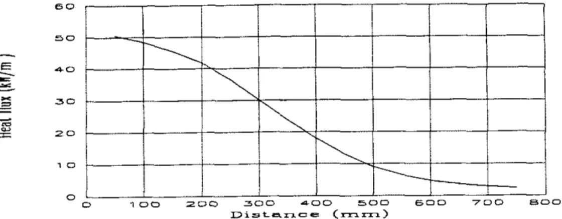
The measured flux distribution being received along the center of the specimen is given in Figure 1. The maximum heat flux is set at 50 k w h 2 for the data shown. The variation along the lateral direction would have a similar profile at other heat flux levels.
Figure 1: Variation of Specimen Incident Heat Flux with Lateral Distance
TEST
MATERLALS
Six typical building materials, supplied by the National Institute of Standards and
.
Technology (NIST), were tested. The thickness of each test specimen is shown inTable 1.
Table 1 : Test Specimens.
Plywood
I
12Fire Retardent (FR.)
1
12Flame Spread Test
Specimen Size Ignition Test Specimen Size Specimen Thickness of Material, mm 155 mm x 800 mm Plywood Polystyrene Foam Polyurethane Foam Gypsum W allboard Composite Board 22 22 16 1 1 155 mm x 155 mm
RESULTS
Ignition
Tests
For the ignition test, the 155 mm wide test specimen was placed at the high heat flux end of the specimen holder. At this location, after accounting for the edge effects, the specimen was subjected to a fairly uniform heat flux along the longitudinal direction.
Experimental ignition test data from the six materials are given in tabular form in
the Appendix A. Each table contains a summary of data collected. The same data are also presented in the following three graphical formats for each material:
i. The inverse of time to ignition (l/tig! versus the incident heat flux (qWe). Based on ignition theory, a straight-line passlng through the data points will intersect the horizontal axis (Mig = 0, i.e. t. lg
+
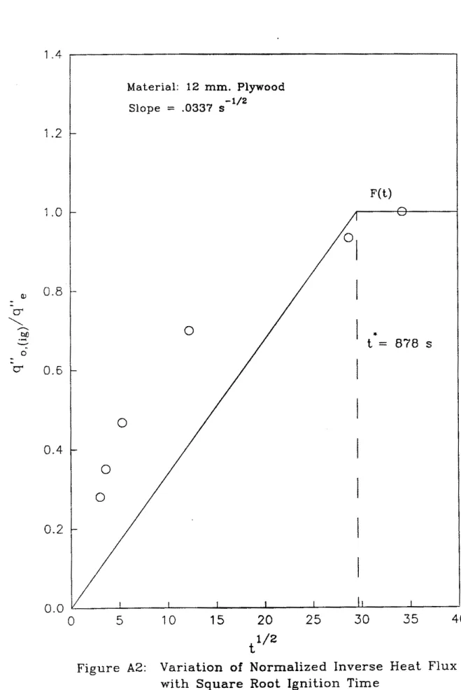
=-) at the minimum heat flux for ignition 11-31,ii. The ratio of the minirnum heat flux for ignition and the incident heat flux (q"o,(ig)/q"e) versus the square root of the time to ignition (4tig). A straight line passing through these data points will intersect the q"o,(ig)/q"e = 1.0 at the time to ignition at minimum heat flux. This time is referred to as the "characteristic equilibrium time (r*)", meaning that a material, when subjected to a constant heat flux, will either ignite before t* or not ignite at all, in the presence of a pilot flame.
...
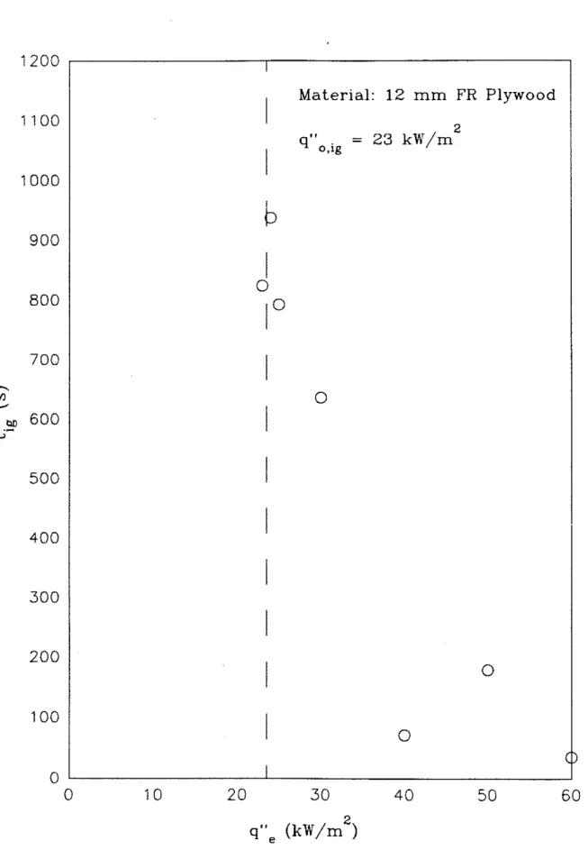
m. The time to ignition (tig) versus incident heat flux (q",). The incident heat flux data will be asymptotic to the minimum heat flux for ignition (qVe -+ q"o,ig).
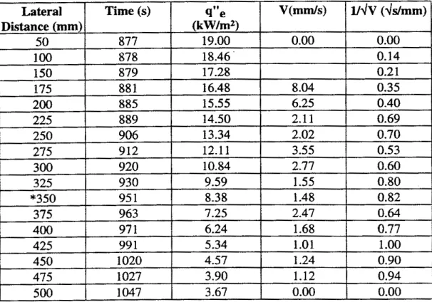
Flame Spread Tests
The flame spread test data for the six materials are given in the Appendix A. For each material, the test was performed three times. The data from the three tests for each material are given in three separate tables. Each table contains a summary of data collected. The data from all three tests are also presented graphically, as the flame front distance vs. time.
DISCUSSION
Plvwood
All the tests were conducted with the grain of the exposed surface of the plywood vertical, i.e., at right angles to the pilot flame. The ignition test results are given in Table A1 and Figures A1 through A3. Figure A2 shows that the ignition experimental data for plywood deviated somewhat from the ignition theory [2-41. The standard deviation of the offset between the experimental data and the chosen function F(t) was 0.19 or 19% of the flux ratio range of 0 to 1.
The flame spread data are given in Table A2 and Figure A4. The flame spread data from the three samples show good consistency and repeatability.
Fire
Retardent PlvwoodA
l
l
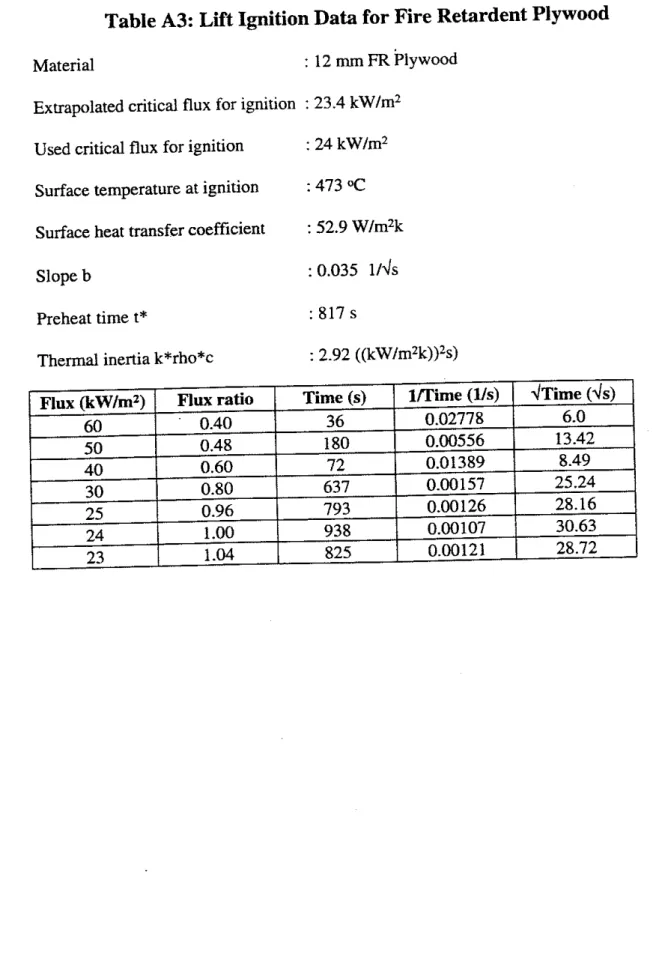
the fire retardent (FR) plywood tests were conducted with the grain of the exposed surface of the plywood vertical. The ignition test results are given in Table A3 and Figures A5 through AS. The ignition test results show irregular variation ofi~nition with incident flux around 40 k ~ l m 2 and at 24 k ~ l m 2 (Table A3).
At the 24 k w h 2 heat flux level, the discrepancy in the experimentally measured value is only 16% from the mean of the readings on either side. The arithmetic mean of measured time to ignition at 25 and 23 k w h 2 is 809 s. The measured time to ignition at 24 k ~ l m 2 is 938 s. Assuming 809 s to be the correct value, indicates a 16% deviation at the 24 k w h 2 measurement.
At 40 kw/m2, however, the "experimental error" is 82%. The Arithmetic mean of time to ignition at 50 and 30 k w h 2 is 409 s. The measured time to ignition at 40 k ~ l m 2 is 72 s. Assuming 409 s to be the correct value, a discrepancy of 82% results. The time to ignition at 30, 40 and 50 kw/m2 are 637, 72 and 180 seconds respectively. Tests at 40 and 50 kw/m2 were repeated to verify this apparently peculiar behavior. The repeat test results were nevertheless very close to the ones reported here at both flux levels.
The flame spread data of FR plywood is given in Table A4 and Figure A8. The three flame spread tests on
FR
plywood do not show good consistency or repeatability. Test 1 and 2 results showed the highest discrepancy, while the tests 1 and 3 displayed fair consistency. Only Test 1 and 3 data were used for the summary results given in Appendix A.Polvstvrene Foam
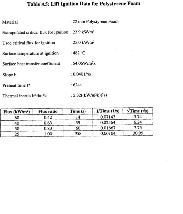
The ignition test results are given in
able
A5 and Figures A9 through A l l . During all the ignition tests, the polystyrene foam specimens melted almost completely before ignition. The ignition times reported are those times of observed flame attachment to the melted polystyrene foam. In the case of easily melting materials, the time of ignition is a strong function of the specimen holder and its orientation. If the holder permits drainage of liquid from the bottom, there would not likely be any flame attachment. Conversely, a slight inclination of the sample holder towards the higher-heat-flux-end would mean that the melted polystyrene foam will ignite earlier.The flame spread data for polystyrene foam are given in Table A6 and Figure A12. The test results also show inconsistent results due to the same reasons outlined above. The polystyrene specimen melted and the liquid accumulated at the bottom of the sample holder before ignition and flame attachment occurred. A LIFT apparatus test with the specimen held vertically would therefore not be an appropriate test for polystyrene foam.
Polvurethane Foam
The ignition test results are given in Table A7 and Figures A13 through A15. From the ignition tests, it was clear that polyurethane foam emits a small quantity of volatile combustibles during the early part of the test. Gaseous combustibles emitted from the polyurethane foam were visibly burning at the pilot flame, increasing the visible thickness of that flame. In all of the tests reported, flame attachment to the specimen took place after a short while. At heat fluxes lower than 27 kwlm2, however, volatile combustibles continued to bum at the pilot flare with no apparent flame attachment to the specimen. For example, at 25 k ~ l m 2 , the volatile combustibles burned at the pilot flame for the initial 40 seconds with no visible flame attachment to the specimen either during this time or afterwards. After the initial 40 s, there was little or no volatile material evolution from the charred polyurethane foam specimen. In all of the ignition tests, polyurethane formed a char layer but otherwise maintained its shape.
The flame spread test results for polyurethane foam are given in Table A8. During the flame spread tests, the polyurethane sample produced volatile combustibles that bumed at the pilot flame but did not produce sustained flame attachment to the specimen. In otber words there was no apparent flame spread on the polyurethane foam.
The ignition and flame spread results for polyurethane foam may imply a sense of fire safety that does not exist. Even though the material does not undergo combustion similar to commonly used wood products, it will produce volatile combustibles very early during fire exposure and perhaps accelerate the rate of spread of fire to other combustibles in the vicinity. LlFT apparatus tests with the specimen held vertically would not therefore provide useful information about the combustibility of polyurethane foam.
Gypsum
Wallboard
The ignition test results on gypsum wailboard are shown in Table A9 and Figures A17 through A19. The gypsum wallboard consisted of a gypsum core with a paper cover on both sides. This paper was the only combustible component in the ,wsum wallboard. The ignition test results of the paper cover showed good agreement with theory.
The flame spread test results on gypsum wallboard are reported in Table A10 and Figure A20. The results refers to the combustion of the paper layer. Flame spread data from the three tests showed fair consistency and repeatability.
The composite material was a board approximately 11 mm (7116") thick and was composed of at least three distinct layers of material laminated together. The face and back layers were approximately 1 rnm thick with a 9 mm core. The face panel consisted of a thin (less than 0.5 mm) finish-layer on top of the 1 mm thick face panel. The back panel did not have a finish layer. The core consisted of particleboard.
During the ignition and flame spread tests, initial exposure to radiation resulted in the formation of 'blisters' on the face layer. The blisters were of various diameters but in the order of about 5 mm. These were formed by the detachment of the laminated face layers from the underlying particleboard core. Further exposure to radiation caused the face layer materials to char and these blisters to rupture, releasing the gas trapped within. While these gases were being released, the horizontal pilot-flame remained unchanged in
both size and color. In previous tests, however, when volatile combustible gases were released (from the test specimen), there was a visually recognizable change in the pilot-flame. Thus, there was no clear evidence that the gases released from the rupturing blisters were combustible.
The ignition data for the composite board are given in Table A1 1 and Figures A21 through A23. The exposed core material charred and subsequently ignited. Visual observations during the tests indicated that the face layer materials did not burn.
The flame spread results are shown in Table A12 and Figures A24. During the flame spread tests, horizontal and vertical spread occurred through areas of the exposed particle-board material. In areas where the face layers were still bonded to the core, the face layers acted as a barrier to flame spread. Flame spread data indicate good reproducibility.
References
1. Anon, "Standard Test Method for Determining Material Ignition and Flame Spread hoperties", ASTM E 1321
-
90, Annual Book of ASTM Standards, American Society for Testing and Materials, Philadelphia, Designation: , V 04.07, 1990.2. Quintiere, I. G., "The Application of Flame Spread Theory to Predict Material
Performances", I. of Research of the National Bureau of Standards, V 93-1, Washington, DC., 1988, pp. 61-70.
3. Quintiere, I. G., Harkleroad, M., "New Concepts for Measuring Flame Spread Properties", Proc. Fire Safety, Science and Engineering
-
A symposium sponsored by ASTM Committee E-5 on Fire Standards and by the Society of Fire Protection Engineers, T.Z. Harmathy (ed.), ASTM STP 882, Philadelphia, Pa., 1985, pp. 239- 267.4. Treya, A., Carpenter, C. and Harkleroad, M., "Effect of Sample Orientation on Piloted Ignition and Flame Spread", Proc. First International Symposium on Fire Safety Science, C. E. Grant, P. 1. Pagni (eds.) ; Hemisphere, Washington, DC, 1986, p. 97.
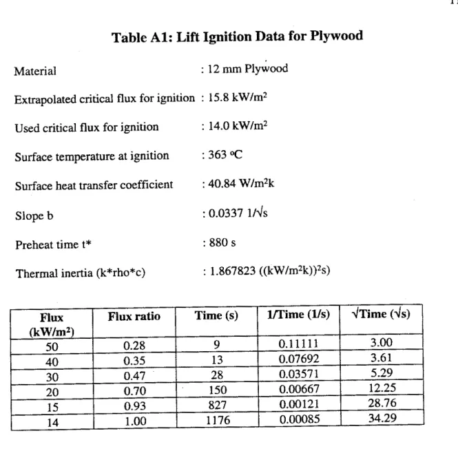
Table A l : Lift Ignition Data for Plywood
Material : 12 mm ~ l ~ w o o d Extrapolated critical flux for ignition : 15.8 kW/m2
Used critical flux for ignition : 14.0 kW/m2 Surface temperature at ignition : 363 OC
Surface heat transfer coefficient : 40.84 W/m2k Slope b : 0.0337 114s Preheat time t* : 880 s
Table A2: Lift Flame Spread Data Report for Plywood
Material : 12 mm Plywood
Heat flux used for flame spread : 19.0 kW/m2
Slope C : 0.0792 rn2ds/kwdm
Flame heating parameter @ : 140.72 (kW/m)2/m
Flame Spread Results for Plywood Test 1 (flux at 50 mm = 19 kW/m2)
1 2 3 mean 105 74 70 82 3.67 2.33 2.14 2.71
13
Flame Spread Results for Plywood Test 2 (flux at 50 mm = 19 kw/m2)
Figure A 2 : Variation of Normalized Inverse Heat Flux
0 1200 1100 1000 900 800 700
-
-
rrl 600.-
4 500 400 300 200 100 0 q S V e (kw/m2)Figure A3: Variation of Ignition Time with Incident Heat Flux
d
Material: 12 m m . PlywoodI
2 q V o . i g = 14 kW/mI
I
I
0
I
I
I
I
I
I
I
1 0
I
I0
0
0 0 10 2 0 3 0 4 0 50 6Table A3: Lift Ignition Data for Fire Retardent Plywood
Material : 12 mm
FR
plywoodExtrapolated critical flux for ignition : 23.4 kW/m2 Used critical flux for ignition : 24 kW/m2 Surface temperature at ignition : 473 OC
Surface heat transfer coefficient : 52.9 W/m2k Slope b : 0.035 114s Preheat time t* : 817 s
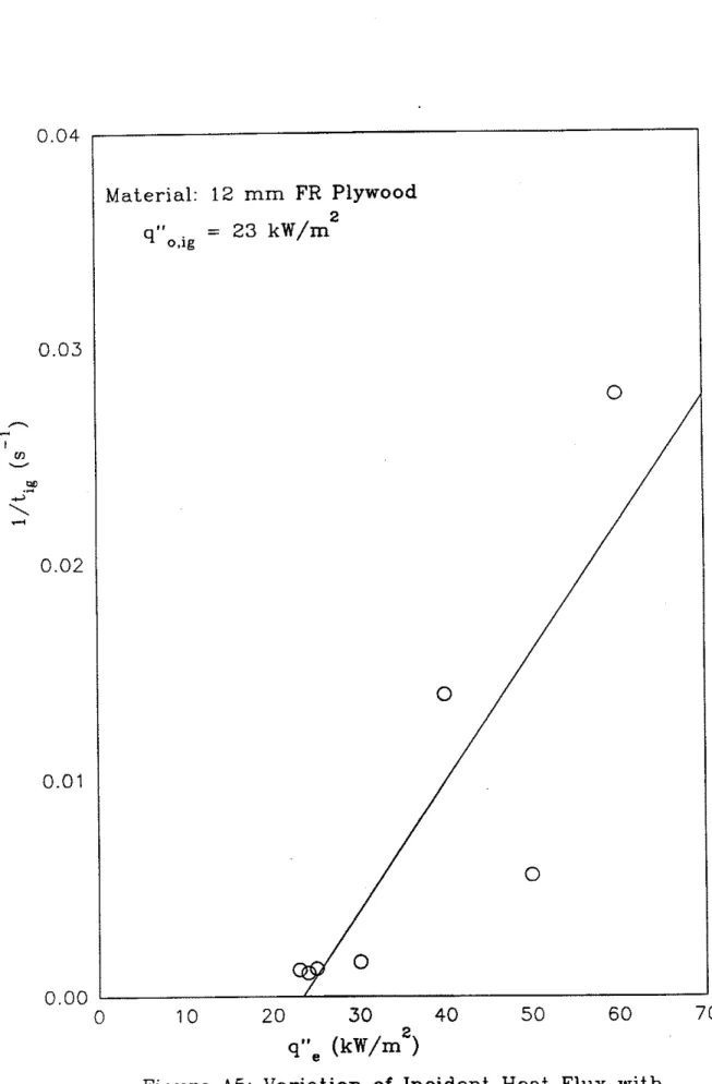
Figure A5: Variation of Incident
Heat
Flux with Inverse of Ignition TimeFigure A 6 : Variation of Normalized Inverse Heat Flux with Square Root of Ignition Time
Material: 12 mm. FR Plywood - 1/2 Slope = .034 s - F(t)
0
- 0 5 10 152
025
3
0
35
40
s",
(kw/rn2)
Table AS: Lift Ignition Data for Polystyrene Foam
Material : 22 mm Polystyrene Foam Extrapolated critical flux for ignition : 23.9 kW/m2
Used critical flux for ignition : 25.0 kW/m2 Surface temperature at ignition : 482 OC
Surface heat transfer coefficient : 54.06W/m2k Slope b : 0.0401/l/s Preheat time t* : 624s
Thermal inertia k*rho*c : 2.32((kW/m2k))2s)
d ~ i m e
(4s)
3.74 6.24 7.75 30.95.
lA'ime (Us) 0.07143 0.02564 0.01667 0.00104 Time (s) 14 39 60 958 Flux (kW/mz) 60 40 30 25 Flux ratio 0.42 0.63 0.83 1.00Table A4: Lift Flame Spread
Data
Report for Polystyrene Foam
Material : 22 mm Polystyrene Foam Heat flux used for flame spread : 29 kW/mz
Slope C : 0.2109 m 2 7 / s l k ~ 7 / m
Flame heating parameter $ : 19.52 (kW/m)2/m
Flame Spread Results for Polystyrene Foam Test 1 (flux at 50 mm = 29 kW/m2)
Flame Spread Results for Polystyrene Foam Test 2 (flux at 50 mm = 29 kW/m2) Min. flux for spread kW/m2
18.49 25.16
Test # 1 2
Min. temp for spread OC
370 496 mean
l / 4 ~
(ddmm) - 0.00 1.36 1.55 0.00 433 V(mm1s) o-P 0.00 0.54 0.42 0.00 21.83 q"e (kW/rn2) 29.00 28.18 26.38 25.16 LateralDistance
50 100 150 175 Time (s) 1308 1312 1450 1483t1/2
Figure A10: Variation of Normalized Inverse Heat Flux with Square Root of Time
/
Material: 22 mrn Polystyrene Foams'.,
(kw/m2)C 0 .- .a .- (I) 0
a
Table A7: Lift Ignition Data for Polyurethane Foam
Material : 22 rnm Polyurethane Foam Extrapolated critical flux for ignition : 11.8 kW/m2
Used critical flux for ignition : 27 kWIm2 Surface temperature at ignition : 5 0 0 C
Surface heat transfer coefficient : 56.29 WIm2k
Slope b : 0.4431 114s
Preheat time t* : 5 s
Thermal inertia k*rho*c : 2.055 ((kW/m?k))2s)
Table
As:
Lift Flame Spread Data Report for Polyurethane Foam
Material : 22 mm Polyurethane Foam Heat flux used for flame spread : 32 kWIm2
he-heat time : 5 s
Flame Spread Results for Polyurethane Foam Test 1 (flux at 50 mm = 32 kWIm2) Lateral Distance (mm) 50 800 Time (s)
-
-- -
9"e (kWlmz)Pilot flare expanded, no flame spread on the specimen.
Flame Spread Results for Polyurethane Foam Test 2 (flux at 50 mm = 32 kWIm2)
Flame Spread Results for Polyurethane Foam Test 3 (flux at 50 mm = 32 kWIm2) I/& (ddmm) ' V(mm/s) 9"e (kWJm2) Lateral
lldv
(ddmm)Pilot flare expanded, no flame spread
on the specimen. Time (s) 50 800 V(mmls) - - - - q"e &W/m2) Lateral
Pilot flare expanded, no flame spread on the specimen. Time (s) 50 800 - - - -
0.8 0.7 0.6 0 . 5 A 0.4 r n ' V M
.*
4 2 \ 3 0.3 0.2 0.1Material: 22 mm Polyurethane Foam
2
q7'o.ig = 27 kW/m
0.0
0
0
10 2030
40 50 60 7 0s",
(kw/m2)Figure A 1 3 : Variation of Incident Heat Flux with
0 1.4 1.2 1.0 0.8 0 6 - 0.4 0.2 0.0 t1/2
Figure A 1 4 : Variation of Normalized Inverse Heat Flux w i t h Square Root of Time
Material: 22
mm
Polyurethane Foam-1/2 Slope = 0.443 s - - - - --
0
Cv C1
C,I
1
(I/
t = 5 s * (31
I
I
I
I I I I I I I I5
10 15 20 2 5 3 0 35
40
10 8 6 4 2 0 4... (kw/m2)Figure A 1 5 : Variation of Ignition Time with Incident Heat Flux
I
I
Material: 22 mm 2 Polyurethane Foam9 " o . i ~ = 27 kW/m
I
I
I
I
I
4)
I
0
I
I
I
0
0
0
I
I
I 0 10 2 0 30 40 50 60 7Table
A9: Lift Ignition Data for Gypsum Wallboard
Material : 16 mm Gypsum Wallboard Extrapolated critical flux for ignition : 20.5 kW/m2
Used critical flux for ignition : 2 1 .0 kW/m2 Surface temperature at ignition :491 OC
Surface heat transfer coefficient : 55.18 W/mzk Slope b : 0.932 114s Preheat time t* : 115s
4 1
Table A10: Lift Flame Spread Data Report for Gypsum Wallboard
Material : 16 mm Gypsum Wallboard Heat flux used for flame spread : 26 kWfmz
Slope C : 0.0853 m z & f k ~ d m r n Flame heating parameter @ : 20.13 (kW/m)zfm
Test #
I
Min. temp for spread 0C1
Min. flux for spread kW/mz1 I 1 o< I 9 64
Flame Spread Results for Gypsum Wallboard Test 1 (flux at 50 mm = 26 kW/mz)
3
I
1531
./.3 I8.09
42 Flame Spread Results for Gypsum Wallboard Test 2 (flux at 50 mm = 26 kWlm2)
q" (kw/rnc)
Figure A 1 7 : Variation of Incident Heat
Flux
withFigure A 1 8 : Variation of Normalized Inverse Heat Flux w i t h Square Root of Time
a a, (I) a m A W
48
Table
A l l : Lift Ignition Data for Composite Board
Material : 11 mm Composite Board Extrapolated critical flux for ignition : 24.7 kW/m2
Used critical flux for ignition : 24. kW/m2 Surface temperature at ignition : 473 "c
Surface heat transfer coefficient : 52.93 W/m2k
Slope b : 0.0307 114s
Preheat time t* : 1058 s
Thermal inertia k*rho*c : 3.774((kW/1n~k))~s)
Table A12: Lift Flame Spread Data Report for Composite Board
Material : 11 mm Composite Board Heat flux used for flame spread : 29 kW/m2
Slope C : 0.341 1 m2.\ls/kwdrnm Flame heating parameter I$ : 1 1.6 1 (kW/m)2/m
Test #
1
2
3
mean
Min. temp for spread OC
279 249 243 256
Min. flux for spread kWIm2
13.70 12.11 11.80
49
Flame Spread Results for Composite Board Test 1 (flux at 50 mm = 29 kW1mz)
Flame Spread Results for Composite Board Test 2 (flux at 50 mm = 29 kWIm2)
Figure A 2 1 : Variation of Incident Heat Flux with Inverse of Ignition Time
q>