Capturing the human figure through a wall
The MIT Faculty has made this article openly available.
Please share
how this access benefits you. Your story matters.
Citation
Adib, Fadel et al.“Capturing the Human Figure through a Wall.” ACM
Transactions on Graphics 34, 6 (October 2015): 1–13
As Published
http://dx.doi.org/10.1145/2816795.2818072
Publisher
Association for Computing Machinery (ACM)
Version
Author's final manuscript
Citable link
http://hdl.handle.net/1721.1/111588
Terms of Use
Creative Commons Attribution-Noncommercial-Share Alike
Capturing the Human Figure Through a Wall
Fadel Adib Chen-Yu Hsu Hongzi Mao Dina Katabi Fr´edo Durand
Massachusetts Institute of Technology
Snapshots are Collected across Time
Sensor is Placed Behind a Wall Captured Human Figure
SENSOR SETUP CAPTURE ALGORITHM
Sensor Head Right Arm Chest Le1 Arm Lower
Le1 Arm Right Arm Lower Feet
Figure 1—Through-wall Capture of the Human Figure. The sensor is placed behind a wall. It emits low-power radio signals. The signals traverse the wall and reflect off different objects in the environment, including the human body. Due to the physics of radio reflections, at every point in time, the sensor captures signal reflections from only a subset of the human body parts. We capture the human figure by analyzing multiple reflection snapshots across time and combining their information to recover the various limbs of the human body.
Abstract
We present RF-Capture, a system that captures the human figure – i.e., a coarse skeleton – through a wall. RF-Capture tracks the 3D positions of a person’s limbs and body parts even when the per-son is fully occluded from its sensor, and does so without placing any markers on the subject’s body. In designing RF-Capture, we built on recent advances in wireless research, which have shown that certain radio frequency (RF) signals can traverse walls and re-flect off the human body, allowing for the detection of human mo-tion through walls. In contrast to these past systems which abstract the entire human body as a single point and find the overall location of that point through walls, we show how we can reconstruct var-ious human body parts and stitch them together to capture the hu-man figure. We built a prototype of RF-Capture and tested it on 15 subjects. Our results show that the system can capture a represen-tative human figure through walls and use it to distinguish between various users.
CR Categories: I.3.7 [Computer Graphics]: Three-Dimensional Graphics and Realism—Animation; H.5.2 [Information Interfaces and Presentation]: User Interfaces—Input devices and strategies; C.2.2 [Computer-Communication Networks]: Network Architec-ture and Design—Wireless Communication;
Keywords: Wireless, Motion Capture, Seeing Through Walls, Hu-man Figure Capture
1
Introduction
Capturing the skeleton of a human body, even with coarse precision, enables many applications in computer graphics, ubiquitous com-puting, surveillance, and user interaction. For example, solutions such as the Kinect allow a user to control smart appliances without touching any hardware through simple gestures, and can customize their behavior by recognizing the identity of the person. Past work on skeletal acquisition has made significant advances in improv-ing precision; however, all existimprov-ing solutions require the subject to either carry sensors on his/her body (e.g., IMUs, cameras) or be within the line of sight of an external sensor (e.g., structured light, time of flight, markers+cameras). In contrast, in this paper, we fo-cus on capturing the human figure – i.e., coarse human skeleton – but without asking the subject to wear any sensor, and even if the person is behind a wall.
To achieve this goal, we build on recent advances in wireless re-search, which have shown that RF (Radio Frequency) signals can be used to find the location of a person from behind a wall, without requiring the person to hold or wear any device [Adib et al. 2014; Seifeldin et al. 2013; Nannuru et al. 2013; Bocca et al. 2013]. These systems operate in a fashion similar to Radar and Sonar, albeit at much lower power. They emit wireless signals at very low power (1/1000 of WiFi) in a frequency range that can traverse walls; the signals reflect off various objects in the environment, including the human body, and they use these reflections to localize the person at any point in time. However, all past systems capture very lim-ited information about the human body. Specifically, either they abstract the whole human body as a single-point reflector, which they track [Adib et al. 2014; Adib and Katabi 2013; Seifeldin et al. 2013; Nannuru et al. 2013], or they classify a handful of forward-backward gestures by matching them against prior training exam-ples [Pu et al. 2013].
The challenge in using RF to capture a human figure is that not all body parts reflect the signal back to the sensors. Specifically, at frequency ranges that traverse walls, human limb curves act as ideal reflectors; hence, they may deflect the signal away from the
sensors rather than back to them. (This is because RF signals that traverse walls have a wavelength of multiple centimeters, which is larger than the surface roughness of human body parts, causing each part to act as a perfect reflector [Beckmann and Spizzichino 1987].) At every point in time, the RF sensors capture signals from only a subset of the human body parts, and the sensors lack semantics to understand which body part is reflecting the signal back at that instant. Furthermore, as a person moves, the reflecting limbs vary; for example, at some point, a person’s left hand may reflect the signal back but not his right hand or his head, while at other times, his head may reflect the signal back but neither of his hands. To overcome this challenge, past systems that use radar techniques to reconstruct a skeleton require surrounding the human body with a very large antenna array that can capture the reflections off his/her body parts, similar to holographic systems deployed in airports. In this paper, we limit ourselves to a compact antenna array that sits in a corner of a room – like a Kinect sensor – and captures the figure of a person behind a wall, as shown in Fig. 1. We present RF-Capture, the first system that can capture the human figure when the person is fully occluded (i.e., in the absence of any path for visible light). RF-Capture has two main algorithmic components: The first component is a coarse-to-fine algorithm that efficiently scans 3D space looking for RF reflections of various human limbs and gen-erating 3D snapshots of those reflections. The second component exploits the fact that due to human motion, consecutive RF snap-shots tend to expose different body parts and diverse perspectives of the same body part. Thus, this component introduces an algo-rithm that identifies human body parts from RF snapshots across time, and stitches multiple snapshots together to capture the human figure.
We leverage the captured figure to deliver novel capabilities. First, we show how the captured figure can be incorporated into a classi-fier to identify different subjects from behind a wall. Our classifi-cation accuracy is 95.7% when distinguishing between 5 users, and becomes 88.2% for 15 users. Second, we show that RF-Capture can identify which body part a user moves through a wall with an accuracy of 99.13% when the user is 3 m away and 76.4% when the user is 8 m away. Finally, we show that RF-Capture can track the palm of a user to within a couple of centimeters, tracing letters that the user writes in the air from behind a wall.
We believe the above results present a significant leap towards hu-man figure capture through walls and full occlusion. However, the current system still has limitations. First, our current model as-sumes that the subject of interest starts by walking towards the de-vice, hence allowing RF-Capture to capture consecutive RF snap-shots that expose various body parts. Second, while the system can track individual body parts facing the device, such as a palm writing in the air, it cannot perform full skeletal tracking. This is because not all body parts appear in all RF snapshots. We believe these limitations can be addressed as our understanding of wireless reflections in the context of computer graphics and vision evolves.
2
Related Work
Motion Capture Systems. Past work for capturing the human skeleton relied on motion capture systems that either require in-strumenting the human body with markers or operate only in di-rect line-of-sight to the human body. Specifically, marker-based methods place various types of sensors on the human body – in-cluding inertial, infrared, RF, acoustic, or ultrasonic sensors – and capture the human skeleton by tracking these various mark-ers, e.g., [Roetenberg et al. 2009; Vlasic et al. 2007; Wang et al. 2014a; Raskar et al. 2007; VIC ; Zeb ]. On the other hand, past markerless methods use cameras and infrared-based techniques – including Kinect, multi-view cameras, moving cameras, and
time-of-flight cameras – and require a direct line-of-sight from the sen-sor to the person’s body, e.g., [Shotton et al. 2013; Ganapathi et al. 2010; Hasler et al. 2009b; Gall et al. 2009; Vlasic et al. 2008; Poppe 2007; Ye et al. 2014]. In contrast to all this past work, RF-Capture focuses on capturing coarse human figures without instrumenting the human body with any markers and operates correctly even if the subject is behind a wall or furniture.
Prior art has also investigated motion capture in partial occlusions, e.g., [Li et al. 2010; Herda et al. 2000; Liu and McMillan 2006; Park and Hodgins 2006; Chai and Hodgins 2005; Wang et al. 2008]. However, these systems require the majority of the human body to be unoccluded from their sensors, and focus on estimating the po-sitions of occluded limbs or missing markers by fitting a model. In contrast, since RF-Capture uses RF signals that can traverse oc-clusions, it works even when the person is fully occluded from its sensor, including scenarios where the subject is behind a wall. Imaging and Reconstruction Algorithms. RF-Capture is related to past work on imaging hidden shapes using light that bounces off corner reflectors in the scene [Velten et al. 2012; Kirmani et al. 2009; Heide et al. 2014]. These past systems operate by estimat-ing the time-of-flight of the object’s reflections bouncestimat-ing off the corner. RF-Capture’s reconstruction problem is closely related to such transient imaging techniques; this is because by pointing a time-resolved camera onto a white patch of a wall, that wall essen-tially becomes a lens-less image sensor with distance information. However, the reconstruction constraints – both in terms of band-width and number of sensors – are more stringent in the case of RF-Capture, which limits itself to 20 antennas and less than 2 GHz of bandwidth (while cameras use thousands of pixels and light has hundreds of THz of bandwidth). This allows these transient imag-ing techniques to achieve higher reconstruction accuracy. Further-more, in contrast to these systems, RF-Capture only captures spec-ular reflections because of the wavelength of RF signals it uses. However, because it uses RF signals that can traverse occlusions, RF-Capture does not require the placement of corner reflectors in the environment. Furthermore, unlike this past work, it does not re-quire the hidden shape to be fully static during the acquisition time, and hence is evaluated on real human subjects.
Additionally, RF-Capture is related to past work in the Graphics and Vision community on specular object reconstruction [Liu et al. 2014; Ihrke et al. 2010]. Specifically, for frequencies that tra-verse walls, reflections off the human body have specular prties. However, past work on specular reconstruction, which oper-ates using visible light, typically assumes the object to be static and non-deformable and aims at recovering surface geometry. In con-trast, in RF-Capture, the setting is more complex since the object is moving and deformable, but the goal is simpler since we intend to recover a coarse figure as opposed to surface geometry.
Radar Systems. Radar systems were the first to use RF reflections to detect and track objects. The vast majority of the radar litera-ture focuses on inanimate objects (e.g., planes, metallic struclitera-tures), as opposed to humans. The radar literature that deals with human subjects can be classified into two categories. The first category is high-frequency imaging radar using terahertz [Woodward et al. 2002], laser [Allen et al. 2003], or millimeter and sub-millimeter waves [Cooper et al. 2008; Dengler et al. 2007; Appleby and An-derton 2007]. These systems are intrinsically different from ours since they operate at much higher frequencies, where the wave-length is comparable to the roughness of the surface, and hence the human body becomes a scatterer as opposed to a reflector [Beck-mann and Spizzichino 1987]. The advantage of these systems is that they can image the human skeleton at a high accuracy (as in airport terahertz security scanners). However, they operate at much shorter distances, cannot deal with occlusions like wall or furniture,
and are expensive and bulky.
The second category uses centimeter-waves, i.e., its carrier fre-quency is around few GHz, similar to our system. These systems have significantly lower resolution than our design. In particular, see-through radar estimates the location of a human but does not reconstruct his/her figure [Ralston et al. 2010; Charvat et al. 2010; Jia et al. 2013; Xu et al. 2012; Le et al. 2009; Dogaru and Le 2008]. This includes commercial products, like 100, Xaver-400, Xaver-800, and Range-R [Huffman et al. 2014]. Unlike RF-Capture, these systems cannot track individual limbs or construct a human figure. On the other hand, the few systems that aim to reconstruct the human body demonstrate their results on a doll cov-ered with foil and require an antenna array larger than the imaged object [Zhuge et al. 2008]. In comparison to these systems, RF-Capture provides finer resolution, and allows capturing human fig-ures with a granularity that is sufficient for distinguishing between a set of 15 people. Also, RF-Capture limits itself to a compact ar-ray about twice the size of a Kinect, as opposed to a large arar-ray that is of the size of the human body. In addition, unlike commer-cial products that target the military [Huffman et al. 2014], which use restricted frequency bands and transmission powers only avail-able to military and law enforcement, RF-Capture meets the FCC regulations for consumer devices.
Finally, RF-Capture’s coarse-to-fine algorithm is inspired by radar lock and track systems of military aircraft, which first identify a coarse location of a target then zoom on its location to track it [Forbes 2013]. In contrast to these systems, however, RF-Capture does not separate searching from tracking into different phases at signal acquisition. Additionally, RF-Capture’s goal of reconstruct-ing a human figure differs from these past systems, resultreconstruct-ing in dif-ferences in the underlying algorithms.
Device-Free Localization and Gesture Recognition. Advances in RF-based indoor localization have led to new systems that can track users without requiring them to carry a wireless transmitter, e.g., [Adib et al. 2014; Joshi et al. 2015; Adib and Katabi 2013; Wang et al. 2014b; Pu et al. 2013; Abdelnasser et al. 2015; Chetty et al. 2012; Wilson and Patwari 2011; Youssef et al. 2007; Nan-nuru et al. 2013; Seifeldin et al. 2013; Adib et al. 2015]. Some of these systems have demonstrated the potential of using RF signals to recognize a handful of forward-backward gestures by matching them against prior training examples [Pu et al. 2013]. Others have demonstrated using narrowband RF signals to map major obstacles and building interiors through walls [Depatla et al. 2015; Mostofi 2012; Gonzalez-Ruiz et al. 2014]. RF-Capture builds on this liter-ature but extracts finer-grain information from RF signals. In par-ticular, it is the only system that can identify which human limb reflects the signal at any time. It is also the only system that can combine those limbs to generate a human figure from behind a wall.
3
Primer
(a) Phase of RF signals: An RF signal is a wave whose phase is a linear function of the traveled distance. By sampling the signal, we can record both its amplitude and its phase. The sampled sig-nal can be represented as a complex discrete function of time t as follows [Tse and Vishwanath 2005]:
st= Ate−j2π
r
λt, (1)
where r is the distance traveled by the signal, λ is its wavelength, and A is its amplitude.
(b) Antenna Arrays: Antenna arrays can be used to identify the spatial direction from which the RF signal arrives. This process leverages the knowledge of the phase of the received signals to
beamformin post-processing as shown in Fig. 2(a).
Mathemati-cally, an N-element antenna array can compute the power P of sig-nals arriving along the direction θ as follows [Orfanidis 2002]:
θ" θ" d" Beam"Direc,on"θ" Time" Δf" delay" Fr eq ue nc y" Transmi8ed"chirp" Reflected"chirp"
(a) Antenna Array (b) Frequency Chirp Figure 2—Measuring Location with RF Signals. (a) Antenna arrays can be used to focus on signals from a specific direction θ. (b) FMCW chirps can be used to obtain time-of-flight (i.e., depth) measurements.
P(θ) = N X n=1 snej2π ndcos θ λ , (2)
where snis the wireless signal received at the n-th antenna, d is the
separation between any two antennas, and λ is the wavelength of the RF signal.
Furthermore, the larger an antenna array is, the stronger its focusing capability is. Specifically, an array of length L has a resolution
∆θ = 0.886λ
L [Orfanidis 2002].
(c) FMCW Frequency Chirps: Frequency Modulated Carrier Wave (FMCW) is a technique that allows a radio device to mea-sure the depth of an RF reflector. An FMCW device transmits a frequency chirp –i.e., a periodic RF signal whose frequency lin-early increases in time, as shown in Fig. 2(b). The chirp reflects off objects in the environment and travels back to the device after the time-of-flight. The device can measure the time-of-flight and use it to infer the depth of the reflector. To do so, the device leverages the linear relationship between time and frequency in chirps. Specif-ically, it measures the time-of-flight (and its associated depth) by measuring the frequency shift between the transmitted and received signal. Mathematically, a frequency chirp of slope k can be used to compute the signal power P emanating from a particular depth r as follows [Mahafza 2013]: P(r) = T X t=1 stej2π kr ct , (3)
where stis the baseband time signal, c is the speed of light, and the
summation is over the duration T of each chirp.
Furthermore, by increasing the bandwidth of the chirp signal, one can achieve finer depth resolution. Specifically, a frequency chirp
of bandwidth B has a depth resolution ∆r = 2Bc [Mahafza 2013].
(d) Eliminating Static Reflectors: To capture the human figure, we first need to separate human reflections from the reflections of other objects in the environment (e.g., walls and furniture). To do so, we use standard background subtraction, where subtraction is performed in the complex domain since an RF signal is a sequence of complex numbers (with magnitude and phase). Specifically, re-flections of static objects remain constant over time and can be eliminated by subtraction. Hence, we collect the reflections of static objects before any human enters the room and subtract them from the received chirps at later times. Of course, this requires knowing whether there are humans in the room or not, which we achieve by leveraging past work on RF-based device-free localization which accurately detects and localizes humans [Adib et al. 2014].
4
RF-Capture Overview
The device: RF-Capture is a system that captures the human fig-ure – i.e., a coarse human skeleton – through walls. It operates by transmitting low-power RF signals (1/1000 the power of WiFi), capturing their reflections off different objects in the environment, and processing these reflections to capture the human figure. RF-Capture’s prototype consists of a T-shaped antenna array, as shown
Ar
ra
y&
Cannot&Capture& Reflec:on&
(a) Simple Reflector (b) Reflections off Human Body (c) Exploiting Motion to Capture Various Body Parts Figure 3—RF Reflections. (a) Only signals that fall along the normal to the surface are reflected back toward the device. (b) The human body has a complex surface, but at any point in time only signals close to the normal to the surface are reflected back toward the device. (c) As the person walks, different body parts reflect signals toward the device and become visible to the device.
in Fig. 1. The vertical segment of the “T” consists of transmit tennas and the horizontal segment of the “T” consists of receive an-tennas. The antennas are connected to an FMCW transceiver which time-multiplexes its transmission between the different transmit an-tennas, and which can be operated from a computer using a USB
cable. The total size of the antenna array is 60×18 cm2.
In contrast to typical techniques for imaging humans such as visible light, x-ray, terahertz, and millimeter-wave, RF-Capture operates at lower frequencies between 5.46GHz and 7.24GHz. The advan-tage of operating at such relatively low RF frequencies is that they traverse walls. Additionally, operating at these frequencies allows us to leverage the low-cost massively-produced RF components in those ranges.
The challenge: The key challenge with operating at this frequency range (5-7GHz) is that the human body acts as a reflector rather than a scatterer. As a result, at any point in time, our antenna ar-ray can capture only a subset of the RF reflections off the human body. To see why this is the case, consider the simplified example in Fig. 3(a). Recall the basic reflection law: reflection angle is equal to the angle of incidence. Thus, while an antenna array can trans-mit signals towards the reflecting body, only signals that fall close to the normal to the surface are reflected back toward the array. In contrast, signals that deviate from the normal to the surface are deflected away from our array, making those parts of the reflector invisible to our device. The human body has a much more complex surface; however the same principle still applies, as illustrated in Fig. 3(b).
The solution idea: Our solution to the above problem exploits user motion to capture his figure. Specifically, while the antenna array receives reflections only from very few points on the user’s surface, these points vary as the person moves, and trace the person’s body. Fig. 3(b) and (c) illustrate this concept. The figures show that as the person walks, the relation between the incident signal and the normal to the surface for his various body parts naturally changes, providing opportunities for capturing the signals reflected from var-ious body parts. Hence, we could capture the instantaneous RF re-flections over consecutive time frames, relate them to each other to identify which reflections are coming from which body part, and combine their information across time and motion to capture the human figure.
In order to transform the above idea into a practical system, we need a design that satisfies two requirements: on one hand, the system needs to achieve spatial resolution sufficient for constructing the human figure; on the other hand, the system should process the signals in real-time at the speed of its acquisition (as in Kinect). The design of RF-Capture harnesses the above idea while satisfy-ing our design requirements. Specifically, the system has two key components:
• Coarse-to-fine 3D Scan: This component generates 3D snap-shots of RF reflections by combining antenna arrays with FMCW chirps. A key consideration in designing this algorithm is to en-sure low computational complexity. Specifically, directly scanning each point in 3D space to collect its reflections is computationally intractable. Thus, this component introduces a coarse-to-fine al-gorithm that starts by scanning 3D reflections at coarse resolution, then zooms in on volumes with high power and recursively refines their reflections. The implementation of this algorithm is based on computing FFTs which allows it to achieve low computational complexity.
• Motion-Based Figure Capture: This component synthesizes con-secutive reflection snapshots to capture the human figure. It oper-ates by segmenting the reflections according to the reflecting body part, aligning them across snapshots while accounting for motion, and then stitching them together to capture the human figure. In §9, we demonstrate that this approach can deliver a spatial resolution sufficient for capturing the human figure and its limbs through walls and occlusions.
Next, we describe these components in detail.
5
Coarse-to-Fine 3D Scan
RF-Capture uses a combination of a 2D antenna array and FMCW chirps to scan the surrounding 3D space for RF reflections. How-ever, since much of the 3D space is empty, it would be highly in-efficient to scan every point in space. Thus, RF-Capture uses a coarse-to-fine algorithm that first performs a coarse resolution scan to identify 3D regions with large reflection power. It then recur-sively zooms in on regions with large reflected power to refine its scan. Below, we explain how this coarse-to-fine scan can be inte-grated with the operation of antenna arrays and FMCW.
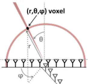
Each voxel in 3D space can be uniquely identified by its spherical coordinates (r, θ, φ) as shown in Fig. 4. By projecting the received signals on θ and φ using the 2D antenna array and on r using the frequency chirp, we can measure the power from a particular 3D voxel. Mathematically, the power arriving from a voxel (r, θ, φ) can be computed as:
P(r, θ, φ) = M X m=1 N X n=1 T X t=1 sn,m,tej2π kr
ctej2πλ sin θ(nd cos φ+md sin φ)
, (4) where N is the number of receive antennas, and M is the number
of transmit antennas, and sn,m,tis the signal received by receive
an-tenna n from transmit anan-tenna m at time t.
Equation 4 shows that the algorithmic complexity for computing the reflection power is cubic for every single 3D voxel. Thus, we want to minimize the number of 3D voxels that we scan while main-taining high resolution of the final 3D reflection snapshot. To do so, we refine the resolution of our antenna array and FMCW chirps re-cursively as described below.
(r,θ,ϕ)&voxel&
θ! r!
ϕ!
Figure 4—Scanning. A 2D antenna array with FMCW ranging can focus on any (r, θ, φ) voxel in 3D.
Used%antennas% Used%antennas% Scanned%
region%
(a) Coarse Estimate (b) Finest Estimate Figure 5—Coarse-to-Fine Angular Scan. We start by using a small num-ber of antennas which gives us a wide beam and coarse angular resolution. Then, we refine our estimate by using more antennas to achieve a narrower beam and finer resolution, but use that beam only to scan regions of interest.
Coarse-to-Fine Angular Scan: RF-Capture exploits an intrinsic property of antenna arrays, namely: the larger an array is, the narrower its beam, and the finer its spatial resolution. Thus, RF-Capture starts with a small array of few antennas, and uses more antennas only to refine regions that exhibit high reflection power. Fig. 5 illustrates this design. The figure uses a 1D array for clarity. In the first iteration of the algorithm, RF-Capture computes power using signals from only the two middle antennas of the array, while ignoring the signal from the other antennas. This results in a small aperture, and hence a very wide beam. Using this wide beam, RF-Capture localizes the person to a wide cone as shown by the red region in Fig. 5(a). In the next iteration, it incorporates two more antennas in the array. However, in this iteration, it does not need to scan the entire angular space, but rather only the space where it had detected a person in the previous iteration (i.e., the red region in Fig. 5(a)). The algorithm proceeds in the same manner until it has incorporated all the antennas in the array and used them to compute the finest possible direction as shown in Fig. 5(b).
While the above description uses a 1D array for illustration, the same argument applies to 2D arrays. In particular, our 2D array has a T-shape. Thus, in each iteration, we refine the resolution by including an extra antenna from the vertical segment and two an-tennas from the horizontal segment.
Coarse-to-Fine Depth Scan: Recall that the depth resolution of FMCW is inversely proportional to the bandwidth of the signal (see §3(c)). Hence, RF-Capture can recursively refine its depth fo-cusing by gradually increasing the amount of bandwidth it uses. Specifically, it starts by using a small chunk of its bandwidth, which would result in very coarse resolution as shown in Fig. 6(a). It then localizes the person to a wide spherical ring. In the following iteration, it uses a larger amount of bandwidth but scans only the spherical ring where it identified the reflector. It proceeds iteratively until it has used all of its bandwidth, as shown in Fig. 6(b). But, what does it mean for us to iteratively increase the bandwidth? Similar to our antenna array iterative approach, we still collect all the data, but process it selectively. Specifically, recall that a
fre-Tx/Rx%
Tx/Rx% Tx/Rx%Tx/Rx% Scanned%
region%
Tx/Rx%
(a) Coarse Estimate (c) Finest Estimate Figure 6—Coarse-to-Fine Depth Scan. We start by using a small chunk of bandwidth which gives us coarse depth resolution. Then, we refine our estimate by adding more bandwidth to achieve finer resolution, but use that bandwidth only to scan regions of interest.
Used%antennas% Scanned%
region%
Figure 7—Coarse-to-Fine 3D Scan. We can partition and iterate jointly using chirps and antenna arrays. In any given iteration, we only scan the small region identified by the previous iteration.
quency chirp consists of a signal whose frequency linearly increases over a sweep as shown in Fig. 2(b). Whereas all the samples of a sweep collectively cover the entire bandwidth, a subset of those samples covers a subset of the sweep’s bandwidth. Similar to iter-atively adding more antennas to our processing, RF-Capture itera-tively adds chirp samples to achieve finer depth resolution. Additional Points: A few points are worth noting:
• RF-Capture performs the above iterative refinement in both FMCW bandwidth and antenna arrays simultaneously as shown in Fig. 7.
• Standard antenna array equations (as described in §3(b) and Fig. 2(a)) rely on an approximation which assumes that the signals received by the different antennas are all parallel. To improve the final accuracy of reconstruction and achieve higher focusing capa-bilities, we use a more complex model in the final iteration of the coarse-to-fine algorithm [Richards 2005]. Specifically, the power from an (x, y, z) voxel in 3D space can be expressed as a function of
the round-trip distances r(n,m)(x, y, z) to each transmit-receive pair
(m, n) as follows:1 P(x, y, z) = M X m=1 N X n=1 T X t=1 sn,m,tej2π kr(n,m)(x,y,z) c tej2π r(n,m)(x,y,z) λ (5)
• Finally, the coarse-to-fine algorithm (in our current implementa-tion) allows RF-Capture to generate one 3D snapshot (a 3D frame) of the reflection power every 75ms on Nvidia Quadro K4200 GPU. This represents a speedup of 160, 000× over a standard non-linear projection of Eq. 5 which requires on average 200 minutes for ren-dering a single time snapshot on the same GPU platform. Further-more, because the switched antenna array has a signal acquisition
1The inverse square law is implicit in s
n,m,t and doesn’t need to be
in-verted in the phased array formulation. This is a standard approximation in antenna arrays since the phase varies by 2π every wavelength, which is a much bigger effect than changes in amplitude. Accounting for the minute variations in amplitude can produce minor sidelobe reductions, but is often negligible [Richards 2005].
time of 80ms, the 75 ms rendering time allows RF-Capture to gen-erate a new 3D snapshot within the same signal acquisition period. In addition, it results in a frame rate that is sufficient to continu-ously track human motion across time. Being able to assume that reflecting bodies smoothly move across a sequence of 3D frames is important for identifying human body parts and tracking them, as we explain in the next section.
6
Motion-based Figure Capture
Now that we have captured 3D snapshots of radio reflections of var-ious human body parts, we need to combine the information across consecutive snapshots to capture the human figure. This process involves the following four steps:
1. Compensation for Depth: Since RF-Capture collects 3D snap-shots as the user moves, the subject’s body is at different depths in different snapshots. Therefore, RF-Capture needs to compen-sate for differences in depth before it can combine information across consecutive snapshots.
2. Compensation for Swaying: As the person walks, his body nat-urally sways. To combine information across consecutive snap-shots, RF-Capture has to compensate for this swaying and re-align the 3D voxels across snapshots.
3. Body Part Segmentation: Recall that each of the 3D snapshots reveals a small number of body parts. In the next step, RF-Capture segments each snapshot to extract the body parts visible in it and label them (e.g., head, chest, left arm, left hand, etc.). 4. Skeletal Stitching: In the final step, RF-Capture uses a simple
model of the human skeleton to combine the detected body parts across a few consecutive snapshots and capture the human figure. In what follows, we describe each of these steps in detail. To make the exposition clearer, we describe these steps by applying them to the output of an experiment collected with RF-Capture. In this ex-periment, the RF-Capture sensor is behind a wall. We ask a user to walk toward the RF-Capture device starting from a distance of about 3 m from the sensor. The antennas of RF-Capture are po-sitioned at 2 m above the ground, so that reflections from humans arrive along upward directions.
6.1 Compensating for Depth
When imaging with an antenna array, an object looks more blurry as it gets farther away from the array. This is because the beam of an antenna array has the shape of a cone, and hence is wider at larger distances. Since our 3D snapshots are taken as the subject walks towards the array, the subject is at different depths in differ-ent snapshots, and hence experiences differdiffer-ent levels of blurriness across snapshots. Thus, before we can combine a subject’s reflec-tions across RF snapshots, we need to compensate for his change in depth.
To do so, we first need to know the subject’s depth in each snapshot. This is easy since our snapshots are three-dimensional by construc-tion –i.e., we know the depth of each voxel that reflects power. Of course, the human body is not flat and hence different body parts exhibit differences in their depth. However, these differences are relatively small. Thus, for our purpose, we take the median depth of the RF reflections in each 3D snapshot, and consider it as the person’s depth in that snapshot.
Next, we compensate for depth-related distortion by deconvolving the power in each snapshot with the point spread function caused by the antenna-array beam at that depth. The point spread function is computed directly from the array equation, Eq. 5, and the decon-volution is done using the Lucy-Richardson method [Lucy 1974]. Fig. 8 illustrates this process. The top row shows different RF snap-shots as the person walks towards the antenna array. The snapsnap-shots
are plotted by slicing the 3D snapshot at the median depth for the reflected signals, and showing the power as a heat map, where red refers to high reflected power and dark blue refers to no reflection. It is clear from this row that reflected bodies look wider and more blurry at larger depths. The second row shows the same snapshots after compensating for depth distortion. These snapshots are less blurry and more focused on the actual reflection points.
6.2 Compensating for Sway
Next, RF-Capture compensates for the user’s sway as he walks by using the reflection from his chest as a pivot. Specifically, because the human chest is the largest convex reflector in the human body, it is expected to be the dominant reflector across the various snap-shots, enabling us to identify it and use it as a pivot to center the snapshots. From an RF perspective, the human chest is said to have the largest radar cross section [Dogaru et al. 2007]. Indeed, the heatmaps in Fig. 8(b) show a dominant reflection (dark red) around the height of the subject’s chest (z = 1.4m).
To align the snapshots, we first determine the dominant reflection point in each snapshot. In most snapshots, this would correspond to the human chest. We then perform robust regression on the heights
of these maxima across snapshots, and reject the outliers.2This
al-lows us to detect snapshots in which the chest is not the most dom-inant reflection point and prevent them from affecting our estimate of the chest location. Once we have identified the chest location in each snapshot, we compensate for minor sways of the human body by aligning the points corresponding to the chest across snapshots. Note that aligning the human body across snapshots makes sense only if the human is walking in the same direction in all of these snapshots. Thus, RF-Capture considers the trajectory of the point with the highest reflection power on the human body, and performs the above alignment only for periods during which the human is walking toward the device without turning around.
6.3 Body Part Segmentation
After identifying the human chest as a pivot and aligning the con-secutive snapshots, we segment the areas around the chest to iden-tify the various human body parts.
Specifically, RF-Capture defines a bounding region centered around the subject’s chest. For example, Fig. 9(a) shows the rectangle in orange centered around the detected subject’s chest. (This is the second image from Fig. 8(b) after sway compensation.) Using the chest as a pivot, RF-Capture automatically segments the remain-der of the heatmap into 8 regions, each corresponding to a different body part of interest. The first region constitutes the rectangle be-low the chest, which corresponds to the user’s be-lower torso, while the region above the chest corresponds to the subject’s head. The re-gions to the left and right of the chest correspond to the arms and the hands. Finally, the regions below the torso correspond to the sub-jects’ legs and feet. In our implementation, we specify the width of the torso region to 35 cm, and the height of the upper torso (chest) to 30 cm, while the lower torso is 55 cm. These numbers work well empirically for 15 different adult subjects with different ages, heights, builds, and genders. We envision that exploiting more pow-erful segmentation and pose estimation algorithms – such as those that employ recognition or probabilistic labeling, e.g., [Mori et al. 2004; Shotton et al. 2013; Hasler et al. 2009a] – would capture better human figures. Such techniques are left for future work. Once RF-Capture performs this segmentation, the blobs in the
2To perform robust regression, we use MATLAB’s default parameters,
i.e., bisquare weighting function with a tuning constant of 4.685, and elim-inate outliers whose heights are more than two standard deviations away from the mean.
Depth = 3 m Depth = 2.8 m Depth = 2.3 m Depth = 2.2 m -0.3 0 0.3 0.6 0.9 x-axis (meters) 0 0.5 1 1.5 2 y-axis (meters) -0.3 0 0.3 0.6 0.9 x-axis (meters) 0 0.5 1 1.5 2 y-axis (meters) -0.3 0 0.3 0.6 0.9 x-axis (meters) 0 0.5 1 1.5 2 y-axis (meters) -0.3 0 0.3 0.6 0.9 x-axis (meters) 0 0.5 1 1.5 2 y-axis (meters)
(a) Heatmaps obtained when slicing each 3D snapshot at its estimated depth
-0.3 0 0.3 0.6 0.9 x-axis (meters) 0 0.5 1 1.5 2 y-axis (meters) -0.3 0 0.3 0.6 0.9 x-axis (meters) 0 0.5 1 1.5 2 y-axis (meters) -0.3 0 0.3 0.6 0.9 x-axis (meters) 0 0.5 1 1.5 2 y-axis (meters) -0.3 0 0.3 0.6 0.9 x-axis (meters) 0 0.5 1 1.5 2 y-axis (meters)
(b) Output after deconvolving the images with the depth-dependent point-spread function
0.3 x 0 -0.3 2.7 3 z 3.3 1.8 0 0.3 0.6 0.9 1.2 1.5 y 0.3 x 0 -0.3 2.5 2.8 z 3.1 1.8 0 0.3 0.6 0.9 1.2 1.5 y 0.3 x 0 -0.3 2.1 2.4 z 2.7 1.8 0 0.3 0.6 0.9 1.2 1.5 y 0.3 x 0 -0.3 1.9 2.2 z 2.5 1.8 1.5 1.2 0.9 0.6 0.3 0 y
(c) Kinect skeletal tracking as a baseline for comparison. We rotate the Kinect output by 45◦to visualize the angles of the limbs as the user moves. Figure 8—RF-Capture’s heatmaps and Kinect skeletal output as a user walks toward the deployed sensors. As the user walks toward the device, RF-Capture captures different parts of his body at different times/distances since its antennas’ perspective changes with respect to his various body parts.
heatmaps of Fig. 8(b) become more meaningful, and can be auto-matically assigned body part labels. For example, for the heatmap generated at 2.8m, it can now automatically detect that the blob to the left of the chest is the right arm, and the blob below it is the right hand. On the other hand, the heatmap at 2.2m shows the subject’s left hand and his head, but none of his right limbs.
To gain a deeper understanding into the segmented images, we use a Kinect sensor as a baseline. The Kinect is placed in the same room as the moving subject, while the RF-Capture sensor is out-side the room. Both devices face the subject. We plot in Fig. 8(c) the output of Kinect skeletal tracking that corresponds to the RF
snapshots in Fig. 8(b). We rotate the Kinect skeletal output by 45◦
in Fig. 8(c) so that we can better visualize the angles of the various limbs. We also perform a coordinate transformation between the RF-Capture’s frame of reference and the Kinect frame of reference to account for the difference in location between the two devices. Comparing Kinect’s output with that of RF-Capture, we note the following observations:
• RF-Capture can typically capture reflections off the human feet across various distances. This is because the feet reflect upward in all cases, and hence they reflect toward RF-Capture’s antennas. • It is difficult for RF-Capture to capture reflections from the user’s legs. This is because even as the legs move, they deflect the incident RF signals away from the antenna array (toward the ground) rather than reflecting them back to the array since the normal to the surface
of the legs stays almost parallel to the ground. (Note that placing the antenna array on the ground instead would enable it to capture a user’s legs but would make it more difficult for the array to capture his head and chest reflections.)
• The tilt of a subject’s arm is an accurate predictor of whether or not RF-Capture can capture its reflections. For example, in the third snapshot of Fig. 8(c) (i.e., at 2.3m), the subject’s right arm (color-coded in pink) is tilted upward; hence, it reflects the incident signal back to RF-Capture’s antennas allowing it to capture the arm’s re-flection. Indeed, this matches RF-Capture’s corresponding (third) heatmap in Fig. 8(b). On the other hand, the subject’s left arm (color-coded in red) is tilted upward in the fourth snapshot (i.e., at 2.2m), allowing RF-Capture to capture its reflections in the corre-sponding heatmap.
6.4 Skeletal Stitching
After segmenting the different images into body parts, RF-Capture stitches the various body parts together across multiple snapshots to capture the human figure. We distinguish between two types of body reflectors: rigid parts and deformable parts:
• Rigid Parts, i.e., head and torso: Once RF-Capture compensates for depth and swaying, these structures do not undergo significant deformations as the subject moves. Hence, RF-Capture sums up each of their regions across the consecutive snapshots (i.e., sum up their reflected power). Doing so provides us with a more
com--0.3 0 0.3 0.6 0.9 x-axis (meters) 0 0.5 1 1.5 2 y-axis (meters) -0.3 0 0.3 0.6 0.9 x-axis (meters) 0 0.5 1 1.5 2 y-axis (meters) 0 0.1 0.2 0.3 0.4 0.5 0.6 0.7 0.8 0.9 1 Chest Head Left Arm Lower Left Arm Right Arm Lower Right Arm Feet
(a) Segmentation (b) Captured Figure Figure 9—Body Part Segmentation and Captured Figure. (a) shows the different regions used to identify body parts, and (b) shows the captured synthesized from 25 time frames.
Chirp& Generator& Transmit&Antennas& Tx1& Tx2& Tx3& Tx4& Switch& Receive&Antennas& Rx1& Rx2& Rx3& Rx4& Switch& Receive&Antennas& Rx5& Rx6& Rx7& Rx8& Switch& Arduino&Control& X X USRP& USRP& USRP& Chirp&Reset& Baseband&1& Baseband&2& USRP& Control&Signals&
…
Figure 10—RF-Capture’s Hardware Schematic. The setup consists of a chirp generator connected to a 2D antenna array via a switching platform. The figure shows the Tx chain, and two of the Rx chains.
plete capture of the user’s torso since we collect different reflection points on its surface as the user walks. Furthermore, we found that such a more complete capture of the torso is very helpful in identi-fying users as we show in §9.
• Deformable parts, i.e., arms and feet: RF-Capture cannot simply add the segments corresponding to the human limbs across snap-shots. This is because as the human moves, his arms sway back and forth, and adding the different snapshots together results in smear-ing the entire image and masksmear-ing the form of the hand. Instead, our approach is to identify the highest-SNR (signal-to-noise ratio) seg-ment for each body part, and select it for the overall human figure. This is because a higher SNR indicates less sensitivity to noise and hence higher reliability.
Finally, to ensure that the resultant figure is smooth, we perform alpha blending [Szeliski 2010]. Fig. 9(b) shows the result of syn-thesizing 25 frames together, collected over a span of 2 seconds as the user walks towards our antenna setup. The figure shows that by combining various snapshots across time/distance, RF-Capture is capable of capturing a coarse skeleton of the human body.
7
Implementation
Our prototype consists of hardware and software components. Hardware: A schematic of RF-Capture’s hardware is presented in Fig. 10. It has the following components:
• FMCW Chirp Generator: We built an FMCW radio on a printed circuit board (PCB) using off-the-shelf circuit components, and based on the design in [Adib et al. 2014]. The resulting radio can be operated from a computer via the USB port. It generates a fre-quency chirp that repeatedly sweeps the band 5.46 − 7.24 GHz ev-ery 2.5 ms. The radio has an average power of 70µWatts, which complies with the FCC regulations for consumer electronics in that band [FCC 1993].
• 2D Antenna array: (shown in Fig. 1): The antenna array consists of 16 receive antennas (horizontal section of the T) and 4 transmit antennas (vertical section of the T); the antennas are log-periodic with 6dBi gain. This multiple-transmit multiple-receive architec-ture is equivalent to a 64-element antenna array. The overall array
dimension is 60 cm × 18 cm.3
• Switching Platform: We connect all four transmit antennas to one switch, so that at any point in time, we transmit the chirp from only one antenna. Similarly, we connect every four receive anten-nas to one switch and one receive chain. Each receive chain is im-plemented using a USRP software radio equipped with an LFRX daughterboard. The sampled signals are sent over an Ethernet ca-ble to a PC for processing. This design allows us to use a single transmit chain and only four receive chains for the entire 2D an-tenna array.
Software: RF-Capture’s algorithms are implemented in software on an Ubuntu 14.04 computer with an i7 processor, 32GB of RAM, and a Nvidia Quadro K4200 GPU. We implement the hardware control and the initial I/O processing in the driver code of the USRP. The coarse-to-fine algorithm in §5 is implemented using CUDA GPU processing to generate reflection snapshots in real-time. In comparison to C processing, the GPU implementation provides a speedup of 36×.
Calibration: FMCW and antenna array techniques rely on very ac-curate phase and frequency measurements. However, various hard-ware components – including filters, wires, switches, and amplifiers – introduce systematic phase and frequency offsets. To make sure these offsets do not introduce errors for our system, we perform a one-time calibration of the system where we connect each of the Tx and Rx chains over the wire and estimate these offsets. We then invert these offsets in software to eliminate their effect.
8
Evaluation Environment
(a) Participants: To evaluate the performance of RF-Capture we recruited 15 participants. Our subjects are between 21–58 years old (µ = 31.4), weigh between 53–93 kg (µ = 78.3), and are between 157–187 cm tall (µ = 175). During the experiments, the subjects wore their daily attire, including shirts, hoodies, and jackets with different fabrics. The experiments were conducted over a span of 5 months; the same subject had different clothes in different experi-ments. These experiments were approved by our IRB.
(b) Experimental Environment: All experiments are performed with the RF-Capture sensor placed behind the wall as shown in Fig. 1. The experiments are performed in a standard office build-ing; the interior walls are standard double dry walls supported by metal frames. The evaluation environment contains office furni-ture including desks, chairs, couches, and computers. The antennas are located 2m above the ground level, ensuring that the device is higher than the tallest subject.
(c) Baseline: We use Kinect for baseline comparison. In our ex-periments, both Kinect and RF-Capture face the subject, but Kinect is in line-of-sight of the subject, while the RF-Capture sensor is behind the room’s wall. We use Kinect’s skeletal output to track the subject, and we perform a coordinate transformation between RF-Capture’s frame of reference and Kinect’s frame of reference.
9
Results
RF-Capture delivers two sets of functions: the ability to capture the human figure through walls, and the ability to identify and track the
3The antenna separation is 4 cm, which is around λ. Such separation is
standard for UWB arrays since the interference region of grating lobes is filtered out by the bandwidth resolution [Schwartz and Steinberg 1998].
Body Part
Identification Accuracy (in %)
Distance (in meters)
99.13 97.72 91.60 87.44 78.53 76.48 0 20 40 60 80 100 3 4 5 6 7 8
Figure 11—Body Part Identification Accuracy with Distance. The fig-ure shows RF-Captfig-ure’s accuracy in identifying the moving body part as a function of the user’s distance to the device.
Estimated
Left Hand Right Hand Left Leg Right Leg Head Undetected
Left Hand 91.6 0.0 5.6 0.0 2.8 0.0 Acutal Right Hand 0.0 90.2 0.0 9.4 0.4 0.0 Left Leg 0.0 0.0 89.7 0.0 0.0 10.3 Right Leg 0.0 0.0 0.0 86.8 0.0 13.2 Head 0.0 0.0 0.0 0.0 90.5 9.5
Table 1—Confusion Matrix of Body Part Identification. The table shows the classification accuracy of the various body parts at 5 m.
trajectory of certain body parts through walls. Below, we evaluate both functions in detail.
9.1 Body Part Identification and Tracking
9.1.1 Body Part Identification
We first evaluate RF-Capture’s ability to detect and distinguish be-tween body parts. We run experiments where we ask each of our subjects to walk toward the device (as shown in Fig. 1), stop at her chosen distance in front of it, then move one of the following body parts: left arm, right arm, left foot, right foot, and head. The subject can stop at any distance between 3m and 8m away from RF-Capture. We perform 100 such experiments. Throughout these experiments, the subjects performed different movements such as: nodding, waving an arm, sliding a leg, or rotating a hand in place. Classification: We would like to identify which body part the sub-ject moved by mapping it to the segmented 3D snapshots. Hence, in each experiment, we collect the reflection snapshots as the user walks and process them according to the algorithms in §5 and §6 to capture the segmented body parts. Then, we focus on the snap-shots after the user stops walking, and moves one limb while stand-ing still. We determine the location of the body part that the user has moved. We compare the identified body part against the user’s reported answer for which body part she/he moved after she/he stopped walking and was standing still.
Results: Fig. 11 plots the classification accuracy among the above 5 body parts as a function of the user’s distance to the RF-Capture sensor. When the user is at 3 m from the antenna setup, the classifi-cation accuracy is 99.13%. The accuracy gradually decreases with distance, and reaches 76.48% when the user is 8 m away.
To better understand the source of the errors, we show the confu-sion matrix in Table 1 for the case where one of our subjects stands 5 m away from RF-Capture. The table shows that most errors come from RF-Capture being unable to detect a user’s body part motion. This is because while the user did move his limbs, some of these motions may have not altered the reflection surface of the limb to cause a change detectable by the antennas. The other main source of classification errors resulted from misclassifying an upper limb as a lower limb, as opposed to confusing a left limb with a right
RF#Capture+
Kinect+
Figure 12—Tracking the Human Hand Through Walls. RF-Capture tracks the subject’s palm through a wall while the Kinect tracks it in line-of-sight. 0 0.2 0.4 0.6 0.8 1 0 1 2 3 4 5 6 7 8 9 10 Fraction of measurements
Tracking Error (in centimeters)
Figure 13—Body Part Tracking Accuracy. The figure shows the CDF of RF-Capture’s accuracy in tracking the 3D trajectory of the subject’s hand.
limb. For example, the right leg and right hand are confused in 5.6% of the experiments, while the right hand and the left hand are never confused. The reason is that our antenna array is wider along the horizontal axis than the vertical axis, as can be seen in Fig. 1. Hence, the antenna has a narrower beam (i.e., higher focusing ca-pability) when scanning horizontally than when it scans vertically.
9.1.2 Body Part Tracking
Next, we would like to evaluate the accuracy of localizing a de-tected body part in RF-Capture’s 3D snapshots. Recall however that human body parts appear in a 3D snapshot only when the inci-dent signal falls along a direction close to the normal to the surface. To ensure that the body part of interest remains visible in the 3D snapshots during the experiment, we focus on localizing the hu-man palm as the user moves his/her hand in front of the device, as in Fig. 12. In particular, the user is asked to raise his hand as in Fig. 12, and write an English letter of his/her choice in mid-air. Note that in each of the 3D snapshots, RF-Capture detects multiple body parts. Hence, we only focus on reflections that change over time and ignore static reflections from static body parts. Once we localize the moving reflection, we attribute it to the location of the subject’s palm and define our error as the difference between this
location and the Kinect-computed location for the subject’s hand.4
Results: We plot the CDF (cumulative distribution function) of the 3D tracking error across 100 experiments in Fig. 13. The figure
shows that the median tracking error is 2.19cm and that the 90th
per-centile error is 4.84cm. These results demonstrate that RF-Capture can track a person’s body part with very high accuracy. To gain further insight into these results, we show two of the letters written by our subjects in Fig. 14. The figure shows the trajectory traced by by RF-Capture (in blue) and Kinect (in red), as the subject wrote the letters “S” and “U”.
9.2 Human Figure Capture and Identification
In this section, we focus on evaluating the quality of the figures captured by RF-Capture, as well as the amount of motion required to capture such figures.
4We perform a coordinate transformation between RF-Capture’s frame
z (meters) 1.65 1.6 1.55 -0.2 x (meters) 0 0.2 1.4 1.6 1.8 2 y (meters) z (meters) 1.6 1.55 1.5 -0.2 x (meters) 0 0.2 2 1.8 1.6 y (meters)
Figure 14—Writing in the Air. The figure shows the output of RF-Capture (in blue) and Kinect (in red) for two sample experiments were the subject wrote the letters “S” and “U” in mid-air.
Body Part
Detection Accuracy (in %)
92 100 100 95 93 96 100 0 20 40 60 80 100 Head Upper
TorsoLowerTorso ArmLeft RightArm FootLeft RightFoot
Body Part
Detection Accuracy (in %)
93 88 77 73 0 20 40 60 80 100 Lower Left Arm Lower Right Arm Upper Left Arm Upper Right Arm
(a) Basic Figure (b) Dividing Arms Figure 15—Body Part Detection Accuracy. In these experiments, the user walks in exactly two steps. The figure shows the percentage of experiments during which RF-Capture was able to capture a particular body part in the human figure, using only two steps of motion.
9.2.1 Amount of Motion Required for Figure Capture
We would like to understand how much walking is needed for our figure capture. Thus, we ask users to walk towards the device, and we divide each experiment into windows during which the subject walks by only two steps. Our intuition is that two steps should be largely sufficient to capture reflections off the different body parts of interest because as a human takes two steps, both his left and right limbs sway back and forth, providing RF-Capture with suffi-cient perspectives to capture their reflections.
Results: Fig. 15(a) shows the results from 100 experiments per-formed by our subjects. The x-axis denotes the body parts of in-terest, and the y-axis shows the percentage of experiments during which we detected each of those body parts. The figure shows that the human torso (both the chest and lower torso) is detected in all experiments; this matches our initial observation that the chest is a large convex reflector that appears across all frames. The other hu-man body parts are detected in more than 92% of the experiments. To understand detection accuracy for finer human figures, we seg-ment each arm into upper and lower parts and show their corre-sponding detection accuracy in Fig. 15(b). The plot shows that the upper arm is detected in a smaller number of experiments, which is also expected because humans usually sway the lower segments of their arms more than the upper segments of their arms as they walk.
9.2.2 Sample Captured Figures
Next, we would like to gain a deeper understanding of the figures captured by RF-Capture, and how they relate to the human’s heights and builds. Thus, we plot in Fig. 16 the figures of four of our sub-jects as output by RF-Capture. Each of the columns corresponds to a different subject, and each of the rows corresponds to the output of an experiment performed on a different day. In the final row of Fig. 16, we overlay the obtained heatmaps over the subject’s photo. Based on these plots, we make the following observations: • Figures of the same subject show resemblance across experi-ments and differ from figures of a different subject. This indicates that RF-Capture can be useful in differentiating between people when they are occluded or behind a wall.
• RF-Capture can capture the height of a subject. Fig. 16 shows
80 90 100
2 3 4 5 6 7 8 9 10 11 12 13 14 15
Identification Accuracy (in %)
Number of Users 98 97 96 96 95 94 94 94 93 93 91 91 89 88
Figure 17—Identification Accuracy as a Function of the Number of Users. RF-Capture uses the captured figures to identify users through classi-fication. The accuracy decreases as the number of users we wish to classify increases.
that subject A’s head is higher than the rest, while subjects B and
Dare around the same height. In reality, subject A is 187cm tall,
while subjects B and D are 170cm and 168cm respectively. • Depending on the subject and the experiment, the feet may ap-pear separated or as a single blob at the bottom of the heatmap. This is typically due to whether the subject is walking with his feet separated or closer to each other.
9.2.3 Human Identification
We want to evaluate whether the human figures generated by RF-Capture reveal enough information to differentiate between people from behind a wall. Hence, we ask our subjects to walk towards Capture from behind a wall, as described in §8(b), and use RF-Capture to synthesize their figures. We run experiments with 15 subjects. In each experiment, we ask one of the subjects to walk toward the device from a distance of 3 m to a distance of 1 m. We run four experiments with each subject across a span of 15 days. Classification: We divide our experiments into a training set and a testing set. In particular, out of each user’s four experiments, three are used for training and one is used for testing. To obtain our feature vectors for classification, we transform the 2D normalized reconstructed human to a 1D-feature vector by concatenating the rows. For dimensionality reduction, we apply PCA on the feature vectors and retain the principal components that cover 99% of the variance. We then use the PCA features to train an SVM model. The SVM model is a multi-class classifier, with a cost of 10, and a first-order polynomial kernel of γ = 1 and coefficient = 1. The classification is performed in MATLAB on the skeleton generated from our C++/CUDA code.
Results: Fig. 17 shows RF-Capture’s classification accuracy as a function of the number of users it is trained on. The results show that when RF-Capture is used to classify between only two users, the accuracy is 98.1%. We note that this accuracy is the average ac-curacy resulting from tests that consist of randomly choosing two of our fifteen subjects, and repeating for different pairs. The standard deviation of this classification across all possible pairs of subjects is 8.1%. As the number of users we wish to classify increases, RF-Capture’s classification accuracy decreases. In particular, looking back at Fig. 17, we see that the accuracy decreases to 92% for clas-sifying 10 subjects, and 88% for 15 subjects.
To gain a deeper understanding into the classification errors, we show the confusion matrix of the 10-subjects experiments in Ta-ble 2. Among these subjects, subject 7 corresponds to subject A in Fig. 16. This subject has been misclassified often as subject 9 in the table. In fact, these two subjects were the tallest among all of our volunteers. Subject 4 is the shortest and is never misclassified as anyone else. Generally, as one would expect, the more distinctive one’s height and build are, the easier it is to classify him.
-0.2 0 0.2 0.4 0.6 0.8 x-axis (meters) 0 0.5 1 1.5 2 y-axis (meters) -0.2 0 0.2 0.4 0.6 0.8 x-axis (meters) 0 0.5 1 1.5 2 y-axis (meters) -0.2 0 0.2 0.4 0.6 0.8 x-axis (meters) 0 0.5 1 1.5 2 y-axis (meters) -0.2 0 0.2 0.4 0.6 0.8 x-axis (meters) 0 0.5 1 1.5 2 y-axis (meters) -0.2 0 0.2 0.4 0.6 0.8 x-axis (meters) 0 0.5 1 1.5 2 y-axis (meters) -0.2 0 0.2 0.4 0.6 0.8 x-axis (meters) 0 0.5 1 1.5 2 y-axis (meters) -0.2 0 0.2 0.4 0.6 0.8 x-axis (meters) 0 0.5 1 1.5 2 y-axis (meters) -0.2 0 0.2 0.4 0.6 0.8 x-axis (meters) 0 0.5 1 1.5 2 y-axis (meters) -0.2 0 0.2 0.4 0.6 0.8 x-axis (meters) 0 0.5 1 1.5 2 y-axis (meters) -0.2 0 0.2 0.4 0.6 0.8 x-axis (meters) 0 0.5 1 1.5 2 y-axis (meters) -0.2 0 0.2 0.4 0.6 0.8 x-axis (meters) 0 0.5 1 1.5 2 y-axis (meters) -0.2 0 0.2 0.4 0.6 0.8 x-axis (meters) 0 0.5 1 1.5 2 y-axis (meters)
(a) Subject A (b) Subject B (c) Subject C (d) Subject D
Figure 16—Human Figures Obtained with RF-Capture. The graphs show examples of the human figures generated by RF-Capture. Each column shows a different human subject, while each row shows figures of the same subject across different experiments.
Estimated 1 2 3 4 5 6 7 8 9 10 1 99.7 0.0 0.3 0.0 0.0 0.0 0.0 0.0 0.0 0.0 2 0.0 96.0 0.4 1.3 0.3 0.0 0.9 0.0 0.4 0.7 3 0.0 0.0 99.9 0.0 0.0 0.1 0.0 0.0 0.0 0.0 Acutal 4 0.0 0.0 0.0 100.0 0.0 0.0 0.0 0.0 0.0 0.0 5 0.0 0.0 2.1 0.0 90.8 0.0 4.8 2.3 0.0 0.0 6 0.0 0.0 5.1 0.0 0.0 94.2 0.0 0.7 0.0 0.0 7 0.0 0.0 0.0 0.0 0.0 0.1 86.9 0.0 13.0 0.0 8 0.0 1.0 0.0 0.0 0.0 0.0 0.8 97.6 0.0 0.6 9 0.0 0.0 0.0 0.0 0.0 0.0 8.8 0.0 91.2 0.0 10 0.0 0.0 0.0 0.0 0.0 0.0 1.1 0.8 0.0 98.1
Table 2—Confusion Matrix of Human Identification. The table shows the classification accuracy for each of our subjects.
10
Discussion
We present RF-Capture, a system that can capture the human figure through walls, and identify users and body parts even if they are fully occluded. However, the system exhibits some limitations: 1. It assumes that the subject starts by walking towards the device,
hence allowing RF-Capture to obtain consecutive RF snapshots that expose his body parts. Future systems should expand this model to a more general class of human motion and activities. 2. The current method captures the human figure by stitching
con-secutive snapshots, and hence cannot perform fine-grained full skeletal tracking across time. Future work may consider com-bining information across multiple RF-Capture sensors to refine the tracking capability.
3. Our implementation adopts a simple model of the human body for segmentation and skeletal stitching. Future work can explore more advanced models to capture finer-grained human skeleta. Despite these limitations, we believe that RF-Capture marks an im-portant step towards motion capture that operates through
occlu-sions and without instrumenting the human body with any markers. It also motivates a new form of motion capture systems that rely on, or are augmented with, RF sensing capabilities. We envision that as our understanding of human reflections in the context of Vision and Graphics evolve, these capabilities would extend human pose capture to new settings. For example, they can expand the reach of gaming consoles, like the Xbox Kinect, or gesture recognition sensors, like those embedded in smart TVs, to operate through ob-structions and cover multiple rooms. They would also enable a new form of ubiquitous sensing which can understand users’ activities, learn their habits, and monitor/react to their needs. In addition, they can provide more representative motion capture models in biome-chanics, ergonomics, and character animation.
Acknowledgements
The authors thank Abe Davis, Haitham Hassanieh, and the mem-bers of NETMIT and the Computer Graphics Group at MIT for their feedback, and the reviewers for their insightful comments. This research is supported by NSF. The Microsoft Research PhD Fellowship has supported Fadel Adib, and the Jacobs Fellowship has supported Chen-Yu Hsu. We thank members of the MIT Cen-ter for Wireless Networks and Mobile Computing: Amazon.com, Cisco, Google, Intel, MediaTek, Microsoft, and Telefonica for their interest and support.
References
ABDELNASSER, H., YOUSSEF, M.,ANDHARRAS, K. A. 2015.
Wigest: A ubiquitous wifi-based gesture recognition system. In IEEE INFOCOM.
ADIB, F.,ANDKATABI, D. 2013. See through walls with Wi-Fi!
In ACM SIGCOMM.
ADIB, F., KABELAC, Z., KATABI, D.,ANDMILLER, R. C. 2014.
3D Tracking via Body Radio Reflections. In Usenix NSDI.
ADIB, F., KABELAC, Z.,ANDKATABI, D. 2015. Multi-Person
Localization via RF Body Reflections. In Usenix NSDI.
ALLEN, B., CURLESS, B.,ANDPOPOVIC´, Z. 2003. The space of
human body shapes: reconstruction and parameterization from range scans. In ACM Transactions on Graphics (TOG).
APPLEBY, R., ANDANDERTON, R. N. 2007. Millimeter-wave
and submillimeter-wave imaging for security and surveillance. Proceedings of the IEEE.
BECKMANN, P.,ANDSPIZZICHINO, A. 1987. The scattering of
electromagnetic waves from rough surfaces. Artech House, Inc.
BOCCA, M., KALTIOKALLIO, O., PATWARI, N.,ANDVENKATA
-SUBRAMANIAN, S. 2013. Multiple target tracking with rf sensor
networks. Mobile Computing, IEEE Transactions on.
CHAI, J., ANDHODGINS, J. K. 2005. Performance animation
from low-dimensional control signals. In ACM Transactions on Graphics (TOG), vol. 24, ACM, 686–696.
CHARVAT, G., KEMPEL, L., ROTHWELL, E., COLEMAN, C.,
ANDMOKOLE, E. 2010. An ultrawideband (UWB)
switched-antenna-array radar imaging system. In IEEE ARRAY.
CHETTY, K., SMITH, G., AND WOODBRIDGE, K. 2012.
Through-the-wall sensing of personnel using passive bistatic wifi radar at standoff distances. IEEE Trans. Geoscience and Remote Sensing.
COOPER, K. B., DENGLER, R. J., LLOMBART, N., BRYLLERT,
T., CHATTOPADHYAY, G., SCHLECHT, E., GILL, J., LEE, C.,
SKALARE, A., MEHDI, I.,ET AL. 2008. Penetrating 3-d
imag-ing at 4-and 25-m range usimag-ing a submillimeter-wave radar. Mi-crowave Theory and Techniques, IEEE Transactions on.
DENGLER, R., COOPER, K., CHATTOPADHYAY, G., MEHDI, I.,
SCHLECHT, E., SKALARE, A., CHEN, C., ANDSIEGEL, P.
2007. 600 ghz imaging radar with 2 cm range resolution. In Microwave Symposium, 2007. IEEE/MTT-S International.
DEPATLA, S., BUCKLAND, L.,ANDMOSTOFI, Y. 2015. X-ray
vi-sion with only wifi power measurements using rytov wave mod-els. IEEE Transactions on Vehicular Technology, special issue on Indoor Localization, Tracking, and Mapping.
DOGARU, T.,ANDLE, C. 2008. Validation of xpatch computer
models for human body radar signature. Tech. rep., Army Re-search Laboratory.
DOGARU, T., NGUYEN, L.,ANDLE, C. 2007. Computer models
of the human body signature for sensing through the wall radar applications. Tech. rep., Army Research Laboratory.
1993. Understanding the Fcc Regulations for Low-power, Non-licensed Transmitters. Office of Engineering and Technology Federal Communications Commission.
FORBES, 2013. How Does A Fighter Jet Lock
Onto And Keep Track Of An Enemy Aircraft?
http://www.forbes.com/sites/quora/2013/07/17/how-does-a-fighter-jet-lock-onto-and-keep-track-of-an-enemy-aircraft/.
GALL, J., STOLL, C., DEAGUIAR, E., THEOBALT, C., ROSEN
-HAHN, B., ANDSEIDEL, H.-P. 2009. Motion capture using
joint skeleton tracking and surface estimation. In IEEE CVPR.
GANAPATHI, V., PLAGEMANN, C., KOLLER, D.,ANDTHRUN,
S. 2010. Real time motion capture using a single time-of-flight camera. In IEEE CVPR.
GONZALEZ-RUIZ, A., GHAFFARKHAH, A., ANDMOSTOFI, Y.
2014. An integrated framework for obstacle mapping with see-through capabilities using laser and wireless channel measure-ment. IEEE Sensors Journal.
HASLER, N., STOLL, C., SUNKEL, M., ROSENHAHN, B.,AND
SEIDEL, H.-P. 2009. A statistical model of human pose and
body shape. In EUROGRAPHICS.
HASLER, N., ROSENHAHN, B., THORMAHLEN, T., WAND, M.,
GALL, J.,ANDSEIDEL, H.-P. 2009. Markerless motion capture
with unsynchronized moving cameras. In IEEE CVPR.
HEIDE, F., XIAO, L., HEIDRICH, W., ANDHULLIN, M. 2014.
Diffuse mirrors: 3d reconstruction from diffuse indirect illumi-nation using inexpensive time-of-flight sensors. In IEEE CVPR.
HERDA, L., FUA, P., PLANKERS, R., BOULIC, R., ANDTHAL
-MANN, D. 2000. Skeleton-based motion capture for robust
re-construction of human motion. In Computer Animation, IEEE.
HUFFMAN, C., HAYES, J.,ANDERICSON, L. 2014.
Through-the-wall sensors (ttws) for law enforcement: Test & evaluation. In ManTech Advanced Systems International.
IHRKE, I., KUTULAKOS, K. N., LENSCH, H., MAGNOR, M.,
ANDHEIDRICH, W. 2010. Transparent and specular object
reconstruction. In Computer Graphics Forum.
JIA, Y., KONG, L., YANG, X.,ANDWANG, K. 2013.
Through-wall-radar localization for stationary human based on life-sign detection. In IEEE RADAR.
JOSHI, K., BHARADIA, D., KOTARU, M., AND KATTI, S.
2015. Wideo: Fine-grained device-free motion tracing using rf backscatter. In Usenix NSDI.
KIRMANI, A., HUTCHISON, T., DAVIS, J., ANDRASKAR, R.
2009. Looking around the corner using transient imaging. In IEEE CVPR.