Publisher’s version / Version de l'éditeur:
Vous avez des questions? Nous pouvons vous aider. Pour communiquer directement avec un auteur, consultez la première page de la revue dans laquelle son article a été publié afin de trouver ses coordonnées. Si vous n’arrivez pas à les repérer, communiquez avec nous à [email protected].
Questions? Contact the NRC Publications Archive team at
[email protected]. If you wish to email the authors directly, please see the first page of the publication for their contact information.
https://publications-cnrc.canada.ca/fra/droits
L’accès à ce site Web et l’utilisation de son contenu sont assujettis aux conditions présentées dans le site LISEZ CES CONDITIONS ATTENTIVEMENT AVANT D’UTILISER CE SITE WEB.
Internal Report (National Research Council of Canada. Institute for Research in Construction), 1992-03
READ THESE TERMS AND CONDITIONS CAREFULLY BEFORE USING THIS WEBSITE. https://nrc-publications.canada.ca/eng/copyright
NRC Publications Archive Record / Notice des Archives des publications du CNRC :
https://nrc-publications.canada.ca/eng/view/object/?id=3c364929-1639-4708-9989-4c99a04b9b06 https://publications-cnrc.canada.ca/fra/voir/objet/?id=3c364929-1639-4708-9989-4c99a04b9b06
NRC Publications Archive
Archives des publications du CNRC
For the publisher’s version, please access the DOI link below./ Pour consulter la version de l’éditeur, utilisez le lien DOI ci-dessous.
https://doi.org/10.4224/20358650
Access and use of this website and the material on it are subject to the Terms and Conditions set forth at Old masonry buildings: earthquake performance and material testing
Council Canada de recherches Canada
Institute for lnstitut de
Research in recherche en
Construction construction
by John Scrivener
This is an internal report of the Institute for Research in Construction. Although not intended for general distribution, it may be cited as a reference in other publications.
Internal Report No. 624
OLD MASONRY BUILDINGS
-
EARTHQUAKE PERFORMANCE
ANDMATERIAL TESTING
by
JOHN C SCRIVENER
ABSTRACT
Some of the recent earthquakes (e.g. Newcastle, Australia in 1989)
have been in areas not considered to have high seismicity. Accordingly old masonry buildings in areas of supposedly low earthquake risk may be vulnerable to damage and even collapse. When they are heritage buildings the cost of damage, whether financial, historical or architectural, may be very great. Thus it is sensible to assess the risk to old masonry heritage buildings even in zones of low seismicity.
The old masonry buildings covered in the review may be of
stonework, clay brickwork or adobe construction. They are most
often thick-walled and not reinforced. Two major areas are
discussed in the review: the determination of the material and structural properties of old masonry by direct and indirect testing and the performance of old masonry in earthquakes.
PREFACE
The Structures Laboratory at the Institute for Research in Construction (IRC) has an ongoing research program to develop guidelines for evaluating the structural adequacy of existing
buildings. Included is the seismic evaluation of older
unreinforced masonry buildings.
This report was prepared for the above program by Dr John Scrivener while he was on sabbatical leave at IRC from June to December 1991. He is Professor of Building in the Department of Architecture and Building, University of Melbourne, Australia.
iii TABLE OF CONTENTS Section Page Abstract Preface Table of Contents 1. INTRODUCTION.
2. MATERIAL PROPERTIES BY DIRECT MECHANIC?LG TESTS 2.1 Tests for Masonry Compressive Strength
and Axial Deformation
2.1.1 Compression tests on large specimens
cut out of structures
2.1.2 Compression tests on cores
cut out of structures 2.1.3 Flat jack tests
2.1.4 Borehole dilatometer tests
2.1.5 Compression tests on reconstituted masonry
2.1.6 Alternative methods for determining masonry compressive strength
2.2 Tests for Mortar Properties 2.3 Tension Tests
2.4 Compression and Tension Test Results 2.5 Shear Tests
2.6 Flexural Tests 2.7 Mortar Bond Tests
3. MATERIAL AND STRUCTURAL PROPERTIES BY INDIRECT TESTS 3.1 Preliminary Investigations
3.2 Sonic and Ultrasonic Pulse Velocity Tests 3.3 Radar Method
3.4 Thermographic Analysis
3.5 Mortar Strength from Hardness Measurement 3.6 Monitoring
4. DYNAMIC TESTS
5. MODELLING OF OLD MASONRY 5.1 Static Modelling 5.2 Dynamic Modelling
6. FIELD PERFORMANCE OF OLD STONE AND BRICK BUILDINGS IN EARTHQUAKES 6.1 Larger Buildings 6.2 Smaller Buildings i i i iii
7. SUMMARY AND DISCUSSION 35
7.1 Mechanical Tests for Compressive Strength
and Axial Deformation 3 5
7.1.1 Direct compression tests on large specimens
and cores 3 5
7.1.2 Flat jack testing of masonry 36
7.1.3 Borehole dilatometer test for masonry 3 7
7.1.4 Reconstituted masonry tests 3 7
7.1.5 Alternative methods for masonry compressive
strength 3 7
7.1.6 Masonry compression test results 3 8
7.1.7 Mortar compression tests 39
7.2 Tension and Shear Tests 3 9
7.2.1 Tension tests 39
7.2.2 Shear tests 39
7.3 General Comments on Direct Mechanical Tests 4 0
7.4. Indirect Tests for Material and Structural
Properties 40
7.4.1 Preliminary investigations and monitoring 40
7.4.2 Sonic and ultrasonic pulse tests 41
7.4.3 Radar method 41
7.4.4 Thermographic analysis 4 2
7.4.5 Mortar strength from hardness 4 2
7.5 Dynamic Tests and Modelling 4 2
7.6 Performance of Masonry in Earthquakes 43
7.6.1 Quality of materials and construction 4 3
7.6.2 Connections between structural elements 44
7.6.3 Structural layout 4 5
7.6.4 Soil-structure interaction 47
7.6.5 General comments on earthquake damage reports 47
8. ACKNOWLEDGEMENTS 48
9. REFERENCES CITED 48
10. REFERENCES CONSULTED BUT NOT CITED 56
11. APPENDIX 64
Table 1: Stonework compression and tension test results 64
Table 2: Brickwork compression and tension test results 65
Figure 1: Sheppard shear test arrangement 67
1. INTRODUCTION
Recently concern has been expressed on the vulnerability of older masonry building stock, particularly heritage buildings, to seismic
shocks. In areas of high seismic activity, the likelihood of
damage in earthquakes may be obvious. It has required the removal or strengthening of hazards such as parapets or ornaments; the strengthening ofthe building by prestressing; the incorporation of a ductile frame to which the masonry is tied; even the removal of the entire building. However in areas of low to medium seismic activity, such as eastern Canada and USA and most of Australia, while the potential for damage is less these areas may experience earthquakes sufficiently severe to cause not only loss of life but also severe damage to the fabric of buildings of historic, architectural or public importance including libraries, churches, schools and government buildings. Often the repair of such damage is expensive or it may be aesthetically impossible. There is a need to discriminate between buildings that need, and do not need, upgrading.
The walls of old masonry buildings are usually thicker than those
in modern buildings. Most often in stonework buildings, the
exterior and interior wythes of the walls are of dressed stone with rubble in between which may or may not contain binding mortar or be bondedto the wythes. Not always is structural connection provided by through-the-wall units. Clay brick masonry walls usually have several wythes mortared together with collar joints and through- the-wall units may be used although there are some examples of construction similar to that of stonework walls.
The seismic behaviour of more recent buildings of 'thin' masonry is fairly well known and understood and modern codes deal with their design and evaluation. Reinforcement is required in higher risk areas. For the older buildings in this group, evaluation has been
treated by ABK (1986).
Bruneau and Boussabah (1991) gave a survey of 'seismic performance
of thick unreinforced masonry'. Their emphasis was on the 'seismic
performance' rather than on the characteristics of 'thick masonry'. Accordingly this report is primarily concerned with testing for material properties of old stone and brick masonry and on appraisal of old masonry in earthquakes.
The review is in two parts. In the first part is the determination of material properties including compressive, tensile, shear, flexural and dynamic properties of masonry, units and mortar using large specimens, cores, flat jack and borehole dilatometer tests,
reconstituted masonry and alternative methods. Indirect tests,
often termed non-destructive tests, such as sonic and ultrasonic pulse, radar, thermographic and mortar hardness tests are investigated. The results of many such tests are recorded. The field performance of old masonry is in the second part and the various factors causing damage, or survival, are discussed.
Over 170 papers were studied in the preparation of this report. Of these, 95 papers turned out to be of direct relevance and are cited in the report and listed in Section 9, References Cited. While the other papers were not found to be of direct relevance to this report, they are sufficiently relevant to the study of seismic appraisal of old masonry buildings to warrant listing in Section 10, References Consulted But Not Cited.
2. MATERIAL PROPERTIES BY DIRECT MECHANICAL TESTS
2.1 Tests for Masonry Compressive Strength and Axial Deformation
There have been several ways in which the vertical compressive
strength and modulus of elasticity (E) of older masonry have been
evaluated by direct tests: on large samples or on cores cut from the structure; on the structure in-situ by flat jack testing or by borehole dilatometertesting; on samples of re-constitutedmasonry; or by alternative methods. The methods are considered in turn.
2.1.1 Compression tests on large specimens cut out of structures
The testing of specimens several courses high and the full thickness of the wall is probably the method most likely to provide the investigator with an accurate estimate of the behaviour of the masonry in the wall. However permission for such sampling may be impossible to obtain on aesthetic or structural grounds. Further it may be difficult to cut out a prismatic specimen, needed for an accurate assessment of stresses, particularly in masonry with weak mortar which can be damaged by the cutting out process.
However these difficulties appear to have been overcome by Pistone and Roccati (1988 and 1991), Modena (1989) and Tomazevic and Anicic (1989) who reported results from wallettes and prisms of clay brickwork cut out from buildings. The latter authors also cut out some stonework specimens. Pistone and Rocatti compared their test results with those from specimens reconstituted in the laboratory and this is discussed in Section 2.1.5.
Other researchers, having taken large samples out of walls, cut out from them smaller specimens for testing. Stonework samples were
taken from a viaduct by Binda et a1 (1982) and 56mm diameter x
122mm high cylinders cut from them in the laboratory both normal and parallel to the bedding plane. Epperson and Abrams (1989) used parts of a four-wythe brick masonry building, built in 1917 and
about to be demolished, to cut out walls and prisms for test. Baronio and Binda (1991) tested specimens from the 11th
century Pavia Tower, which collapsed in 1989.
"The medieval rubble walls, 2.8m thick at the ground floor, were internally made with a sort of conglomerate obtained with
alternate layers of mortars and pieces of stones and bricks and externally cladd with solid bricks. The average thickness of this cladding was 0.15 m."
The average compressive strength of the masonry measured on prisms
cut from large blocks was 2.8 MPa. The paper does not indicate
whether the prisms were of the full width of the wall.
Apparently in all of these cases the masonry was bonded with mortars which were strong enough to withstand the further cutting
process. Schafer (1991), in a study of medieval masonry and
mortar, dipped the samples cut out of walls in liquid paraffin wax which when dry held the masonry together while prismatic specimens were cut. The dried wax was melted off in hot water before testing of the specimens.
With measurements taken of vertical deformation, the static stress/ strain behaviour under vertical uni-axial loading can be plotted. As the stress/strain curve for masonry is seldom a straight line even at low stresses, some researchers in order to indicate the shape of the stress/strain curve from zero to maximum stress quote
more than one secant value of modulus of elasticity (E). For
instance Pistone and Roccati (1991) quoted modulus of elasticity
values obtained at 10, 40 and 80% of the maximum stress. Other
researchers quote only one secant value and while it is often obtained at one third of the maximum compressive stress this is not universal.
Johnson et a1 (1982) instrumented areas of brickwork cladding with Demec gauges and measured the distances between the gauge points before cutting the areas out of the building. In the laboratory the initial elastic recovery and stress/strain relationships were determined. The purpose of the investigation was to establish the loads on the supporting concrete nibs when distressed brickwork was removed for replacement by new brickwork. The authors' wrote:
"The interpretation of the on-site strain readings and their relationship to the laboratory tests is complicated by a
number of factors
-
for example:(a) Brickwork is not perfectly elastic and on repeated loading it exhibits both permanent strain and hysteresis. (b) The repeated load tests on the specimens recovered from
the gable walls produced stress/strain hysteresis effects which were not consistent. However, tests on laboratory- built samples do show a more consistent trend indicating increased permanent set with repeated loadings.
(c) The amount of strain recovery measured on identical specimens varies depending on the length of time the load has been sustained. Generally, the longer the load has
been applied the smaller the strain recovery. Thus the observed elastic modulus on recovery will vary depending on the length of time that the load has been maintained." The above is a good example of the need for proper test procedures and interpretation of results from samples cut out of buildings. The results of these tests and those to follow are recorded in Table 1 for stonework and Table 2 for brickwork in the Appendix.
2.1.2 Compression tests on cores cut out of structures
Two corings of 80 mm diameter for sampling were taken from a pier
of a viaduct by Binda et a1 (1982).
Penelis et a1 (1983) reported that 19 cores of 100 mm diameter were taken from a monument from which mortar and brick specimens were prepared for mechanical tests, including bond strengths between
bricks and mortar, and chemical analyses. The mechanical test
data were also used for the indirect determination of compressive strength and modulus of elasticity of the masonry, using semi- empirical relationships established by current codes, and the results compared with test results from the full cores. Unfortunately the numerical results were not reported.
2.1.3 Flat jack tests
Flat jack testing is well known for the determination of mechanical properties of rock masses. For brick masonry two plane cuttings perpendicular to the wall face are made in mortar bed joints a few units apart and special thin jacks, 400 x 200 x 10mm thickness (or less), are inserted in the cuts. The two jacks therefore compress a masonry sample of reasonable size (Rossi (1985) used 400 x 400 x 200mm). With the recording of deformations in the load direction,
the stress - strain history can be obtained. The load to cause
first cracks in the bricks enables the masonry compressive capacity to be estimated. The results have to be adjusted (see later) as the masonry on which the test is conducted is confined on three
sides and free on the fourth.
Cutting into a masonry bed releases stress and causes a partial
closure of the cut. Use may be made of this with the first cut to
determine the level of compressive stress in the masonry. Measuring points are installed on the face of the masonry above and below the cut and the initial distance between them recorded. On cutting this distance is reduced. The jacking force required to return the distance to its original amount may then be used to
calculate the original stress level. A correction factor is
required to take account of the effect of the flat jack. The tests of Rossi (1985) show that, for clay brick masonry laboratory specimens, the deformation behaviour on jack loading and unloading are nearly identical.
5 Rossi (1985) conducted a series of tests on large-size brick masonry specimens built in the laboratory to calibrate his jacks and to evaluate the reliability of flat jack tests in different loading conditions. He found that 400 x 200mm flat jacks gave
reliable results
-
within 4% for stresses between 1.5 and 2.25 MPaand 12% low for stress of 0.75 MPa and within 9% for modulus of
elasticity. A smaller jack, 240 x 120 mm, while satisfactory for
the determination of masonry stress level was up to 116% in excess for modulus of elasticity. Rossi believed this to be due to the small number of mortar beds in the masonry sample tested by flat jack loading which was therefore unrepresentative of the overall behaviour of the masonry.
Tests on existing structures are reported by Binda et a1 (1982), Tomazevic and Anicic (1989) and Modena et a1 (1991) on stone masonry, and by Binda et a1 (1982 and 1983), Rossi (1982, 1985, 1987, 1988 and 1990), Modena (19891, Tomazevic and Anicic (1989), and Epperson and Abrams (1989) on brick masonry.
Kingsley and Noland (1987) wrote that most brick units made in USA prior to the early 1930's were not extruded and therefore may have a depression, termed a frog, caused by the manufacturing process. The frog is not always filled with mortar during bricklaying particularly when the brick is laid frog downward. When a frog is adjacent to the flat jack complete contact with the masonry surface cannot be achieved. They used one or more thin flat jacks inserted adjacent to the 'working' flat jack to act as fluid cushion 'shims' to overcome this problem. The shim jacks deformed into any voids or irregularities but they could be taken out easily after the
removal of the undeformed working jack. Thus a uniform pressure
was applied on an uneven surface of masonry.
Wallettes and prisms cut out of a four-wythe brick masonry building constructed in 1917 were subjected to various compressive loads in
a rig by Epperson and Abrams (1989). The results from flat jack
testing were compared against the actual loads and stress/strain results. The authors concluded:
(a) the estimation of vertical stress using a single flat
jack exceededthe actual stress by less than 5 per cent.
(b) as the deflection of the masonry surrounding the flat
jack was sensitive to localvariations, the determination
of the pressure required to restore the brickwork to its original position was slightly subjective.
(c) the apparent modulus of elasticity as determined by the flat jacks increased as the applied vertical compressive stress on a test wall was increased. This may be due to an increase in the peripheral restraint to the brickwork immediately adjacent to the test location.
(d) the ratio of moduli of elasticity obtained from flat jack results and prism tests varied from 1.0 at zero vertical stress to 1.6 at vertical stress of 0.79 MPa.
(e) the ratio of moduli of elasticity obtained from flat jack results and wall tests varied from 1.7 at zero vertical stress to 0.9 at vertical stress of 0.79 MPa.
The results from several flat jack tests are given in Tables 1 and 2 in the Appendix.
Numerical modelling of flat jack testing of masonry has been carried out by Jurina and Peano (1982), Sacchi and Taliercio (1986) and Maydl (1991). In the second and third papers finite element computer programs were used and the experimental and computer results compared.
Two draft standards for flat jack testing have been produced by
ASTM (1991A and 1991B), one on co~mpressive stress estimation and
other on deformability properties.
2.1.4 Borehole dilatometer tests
Rossi (1990) reported:
"Using the tests with parallel flat jacks can only determine the deformability characteristics of the superficial layer of masonry. In order to acquire information on the deformability characteristics of the internal masonry it becomes necessary to conduct dilatometric tests using boreholes made by coring. A special probe about 25 cm long applies uniform hydrostatic pressure on the borehole surface, and the measurement of the
consequent deformation determines the modulus o f
deformability."
The borehole dilatometer was used in investigations on the Tower of Pisa foundation.
According to de Vekey (1991A), the technique for the 'internal
fracture test' was described by Chabowski et a1 (1980). de Vekey
reported that recent calibration tests for U.K. masonry using various units showed that the method was not suitable for materials with a compressive strength below 7 MPa. The development of a more consistent version is underway.
2.1.5 Compression tests on reconstituted masonry
Some researchers have reconstituted old masonry, or mortar, in the laboratory.
Tomazevic and Sheppard (1982) constructed stone masonry walls in the laboratory,
"using the materials and workmanship typical of the region of origin. In this way the original quality of the walls was successfully reproduced."
Further details were not given. The walls were built of two layers of uncoursed or partially-coursed limestone blocks, the inner part
of the wall being infilled with smaller stones. Lime-sand or
clayey-sand mortar of poor quality was used. In most cases the
wall thickness exceeded 500mrn. While the authors' prime objective
was to compare the properties of 'original' walls against those of walls strengthened with cement grout, only the 'originalf properties are of interest in this study and they are recorded in
Table 1 in the Appendix.
Sheppard (1985), in attempting to compare the strength of an existing wall with the strength of the same wall incorporating cement grouting, built and tested two wall elements out of masonry taken from an adjacent and similar building. He used laboratory- prepared mortar of the estimated strength of that in the existing
wall. Angotti et a1 (1991) also reported the tests and results.
Pistone and Roccati (1988) compared the compression test results of 'undisturbed samples' (i.e. a wallette and two prisms cut out of a building) with the result obtained from a reconstituted prism of the same bricks and mortar imitating the actual bonding material. The reconstituted prism failed at a significantly lower stress than the 'undisturbed samples' and its deformability was much greater. The authors concluded that:
"in all likelihood the phenomenon of mortar anelastic compaction, whose effects in undisturbed samples are to a considerable extent gradually exhausted under service conditions, had in this case its full effect during the
(reconstituted prism) test."
In a further paper, Pistone and Roccati (1991) aimed: . ~
"to simulate the behaviour of this masonry by means of specimens produced with old bricks and freshly manufactured mortar, either identical to the ancient ones or possessing higher strength, but always within predetermined limits. As has been recognized in recent years, it is of essential importance to be able to reproduce ancient masonry with sufficient accuracy in order not to alter the fabric of existing buildings with the addition of modern materials whose long-term behaviour is unknown (such as, for instance, epoxy resins); or else with exceedingly stiff materials, such as high strength cement mortars, that may affect stiffness distribution in ancient walls. To attain this objective, the earlier stage of the research focused on the definition of suitable methods for the reproduction of ancient mortar with contemporary materials."
They a g a i n compared r e s u l t s from an ' u n d i s t u r b e d sample' and r e c o n s t i t u t e d specimens c o n s t r u c t e d w i t h two d i f f e r e n t l i m e
m o r t a r s . The ' u n d i s t u r b e d sample' compressive s t r e n g t h l a y between t h e mean s t r e n g t h s o f t h e r e c o n s t i t u t e d specimens. I n r e g a r d t o deformation, t h e r e s u l t s o f t h e s t r e s s - s t r a i n c u r v e s f o r t h e weaker of t h e two r e c o n s t i t u t e d specimen s e r i e s and t h e ' u n d i s t u r b e d sample' a g r e e d r e a s o n a b l y c l o s e l y (see Table 2 ) . Accordingly t h e p o i n t made i n t h e i r e a r l i e r p a p e r c o u l d n o t b e confirmed.
R e s u l t s o f t e s t s on brickwork b u i l t up from o l d b r i c k s and new m o r t a r s are r e p o r t e d by Modena ( 1 9 8 9 ) . The m o r t a r s "were composed a c c o r d i n g t o t h e a n c i e n t formulas" b u t no f u r t h e r e x p l a n a t i o n o r r e f e r e n c e was g i v e n . While some compressive s t r e n g t h s were
comparable w i t h r e s u l t s from a c t u a l o l d brickwork o t h e r s w e r e n o t and t h e moduli of e l a s t i c i t y w e r e n o t comparable.
The e x p e r i m e n t a l e v a l u a t i o n of t h e compressive p r o p e r t i e s of t u f f masonry w a l l e t t e s , u s i n g t u f f b l o c k s o b t a i n e d from t h e d e m o l i t i o n of o l d b u i l d i n g s and m o r t a r made up i n t h e l a b o r a t o r y t o have a compression s t r e n g t h (2.0 t o 3.0 MPa) t y p i c a l o f t h e o l d pozzolan m o r t a r s , was conducted by F a e l l a e t a 1 ( 1 9 9 1 ) . The d a t a was needed f o r p r o j e c t s i n which o l d masonry s t r u c t u r e s were t o be s t r e n g t h e n e d .
F u r t h e r r e s e a r c h , on t h e r e c o n s t i t u t i o n o f o l d m o r t a r s , i s g i v e n i n S e c t i o n 2.2.
2.1.6 Alternative methods for determining masonry compressive strength
Pume (1991) e s t i m a t e d t h e unconfined compressive s t r e n g t h o f o l d brickwork i n t h e f o l l o w i n g way. H e o b t a i n e d t h e b r i c k s t r e n g t h , p r e f e r a b l y from v e r t i c a l c o r e s t a k e n from a b r i c k removed from t h e w a l l , and a d j u s t e d f o r h e i g h t / w i d t h r a t i o from c a l i b r a t i o n c u r v e s t o g e t t h e unconfined b r i c k s t r e n g t h . Then h e determined t h e h a r d n e s s of t h e mortar, by a t e c h n i q u e d e s c r i b e d i n S e c t i o n 3.5, and u s e d an e m p i r i c a l formula t o e s t i m a t e t h e m o r t a r compressive s t r e n g t h . F i n a l l y , w i t h b o t h t h e b r i c k and m o r t a r s t r e n g t h s and u s i n g f u r t h e r c a l i b r a t i o n c u r v e s , h e e s t i m a t e d t h e masonry unconfined compressive s t r e n g t h which he c o n s i d e r e d h e o b t a i n e d w i t h i n 10% accuracy.
An i n t e r e s t i n g d i f f e r e n t approach was g i v e n by Berger (1989) who, from new masonry c o n s t r u c t e d i n t h e l a b o r a t o r y , t o o k 2 0 t o 30mm d i a m e t e r c o r e s p a r a l l e l t o m o r t a r beds, some i n t h e b r i c k s a l o n e and some c o n t a i n i n g a m o r t a r bed. He s t a t e d t h a t he c o u l d show t h e o r e t i c a l l y and e x p e r i m e n t a l l y t h a t t h e r a t i o between t h e t e n s i l e s t r e n g t h s o f t h e c o r e s w i t h and w i t h o u t m o r t a r beds as o b t a i n e d by t h e B r a z i l i a n t e s t w a s t h e same as t h e r a t i o between t h e compressive s t r e n g t h s of t h e masonry and t h e u n i t . Accordingly masonry compressive s t r e n g t h s c o u l d be found f r o m t e s t i n g c o r e s i n d i a g o n a l compression p r o v i d e d t h a t t h e compressive s t r e n g t h o f t h e
brick unit was known. He found that samples could be taken without damage if the operating speed of the diamond-tipped coring bit and the pressure of the cooling water was strictly controlled provided
that the mortar compressive strength was above 0.55 MPa. The
method was not suitable for brick masonry with thick bed joints, or for stone masonry and it has yet to be tried on old brickwork. In an attempt to remove this drawback Berger experimented with the determination of strengths using ultrasonic pulse velocities of brick and mortar with some success and he reported that tests on a larger number of specimens of different kinds of masonry were underway.
2.2 Tests for Mortar Properties
With masonry comprised of relatively low strength units (say less
than 10 m a ) , which is often the situation in historical buildings
of brick, the compressive strength of the mortar has a more marked influence on the compressive strength of the masonry than for higher strength units.
After chemical analyses of the existing mortar obtained from cores, Penelis et a1 (1983) prepared compatible grouts for strengthening, and mechanical tests were conducted on these 'reconstituted' grouts. Results were not reported.
Baronio and Binda (1991) investigated the mortar from the 11th century Pavia Tower which collapsed in 1989. The objective of the research was to determine a procedure for the investigation of
historic mortars. In the process petrographic/mineralogical,
chemical, physical and mechanical analyses were developed on the sampled mortars.
"These tests are carried out in order to obtain information for various purposes in the conservation of historic buildings. Some of these purposes are listed below:
(a) type of binder and aggregates used in the original mortar: sampling has to be done only in protected areas in order to avoid the recovering of leaked [leached] materials;
(b) type of binder and aggregates plus grain size distribution: sampling has to be performed as in a), but a great quantity of material needs to be extracted; (c) kind and degree of deterioration: all the decayed areas
of the walls have to be previously inspected in order to find the most representative sites for sampling;
(d) strength and other mechanical parameters. Only specimens of significant size can be tested, then sampling is
useful only in the case when these dimensions are guaranteed;
(e) presence of soluble salts in the decayed materials: sampling must be done without use of water."
The authors commented on the difficulty of directly measuring the mechanical strength of mortars as the mortar joints were thin and of variable thickness. However they were able to cut mortar cubes of mean side length 30 mm from the recovered blocks of masonry. The mean compressive strength obtained was high, some 2.3 times the mean wall strength, and the strengths ranged from 2.9 to 13.4 MPa. Their paper did not state whether the strengths quoted were adjusted to unconfined strengths which may have been difficult with
such small specimens. Moduli of elasticity were found to lie
between 270 and 1580 MPa.
Three further papers from the 9th International Brick/Block Masonry Conference, held in October 1991, discussed the analysis of
historic mortars, particularly chemical and mineralogical
investigations, with the objective of finding satisfactory repair mortars. These papers, each written in German, were by Huesmann and Knofel (1991), Knofel and Schubert (1991) and Middendorf and Knofel (1991).
2 . 3 T e n s i o n T e s t s
In the diagonal compression or Brazilian test, for brittle low tensile strength materials, a cylinder is loaded diametrically in compression causing a splitting tension failure along the loaded diameter. Assuming that the material is homogeneous and isotropic, the tension strength obtained is also the 'shear' strength.
Splittingtension tests on laboratory-made limestone specimens were reported by Tomazevic and Sheppard (1982) and the results were used in direct comparison with other 'referential tensile strengths' calculated from the shear resistance of walls subjected to a constant vertical load and increasing horizontal load.
Tomazevic and ~ n i c i c (1989) reported results of tests on specimens
cut out of old stonework and old brick masonry. Surprisingly they found that results from shearing tests were at least three times greater than the tensile test results and they suggest that "the differences in the results are due to the different testing procedures used for the determination of the tensile and shearing strength of the masonry, which have caused different stress states in the tested specimens, and consequently different failure mechanisms." While this is no doubt true, the author believes that the large difference is more likely due to the addition of vertical stresses from superimposed loads in the shear test specimens.
2 . 4 Compression and Tension Test Results
Results of the tests described above are given, for stonework in
Table 1 and for brickwork in Table 2, in the Appendix.
2.5 Shear Tests
There are two types of shear tests, one to find the in-plane horizontal sliding resistance along a mortar bed (sometimes termed the 'shove' or 'push' test) and the other to determine the in-plane shear resistance of a wall or wallette which results in a diagonally-cracked specimen. For the latter case the specimen may be a wall supported at its base and 'racked' by a horizontal load applied, say, at the top of the wall or the specimen may be a wallette which is diagonally compressed.
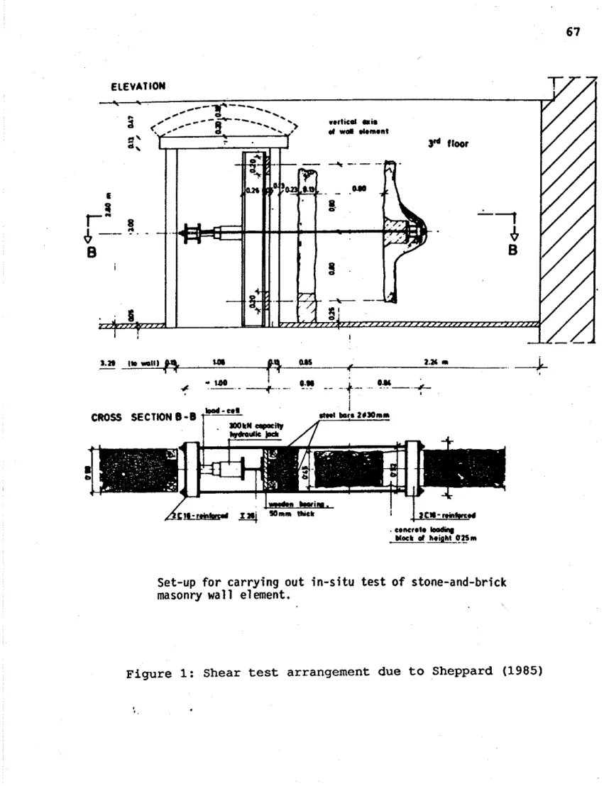
For the shear resistance of a portion of in-situ masonry, Sheppard (1985) used the following method. About 300 mm from a door opening two vertical slits, 1600 mm high and 1000 mm apart, were cut creating an intact wall element 1600 mm high and 800 mm effective width. At wall mid- height a bearing block was fixed to one edge of the wall element so that a horizontal load could be applied with a jack which acted on the wall via two horizontal steel ties fixed
to two transverse I-beams as shown in Fig. 1. The jack's
horizontal reaction was transferred to a vertically-erected I-beam whose points of support 1600mm apart coincided vertically with the two points of support of the tested wall element. This set-up creates two symmetrically-arranged wall elements, 800mm x 800mm, with practically full fixity on one surface (top and bottom respectively). As the horizontal load was increased monotonically and incrementally with intermediate loading steps, horizontal deformations were recorded enabling load-deformation diagrams to be
plotted. Sheppard loaded to the maximum horizontal load when
diagonal cracks occurred. The cracked masonry was repaired using cement grout and the wall was retested. The tests and results were also reported by Angotti et a1 (1991).
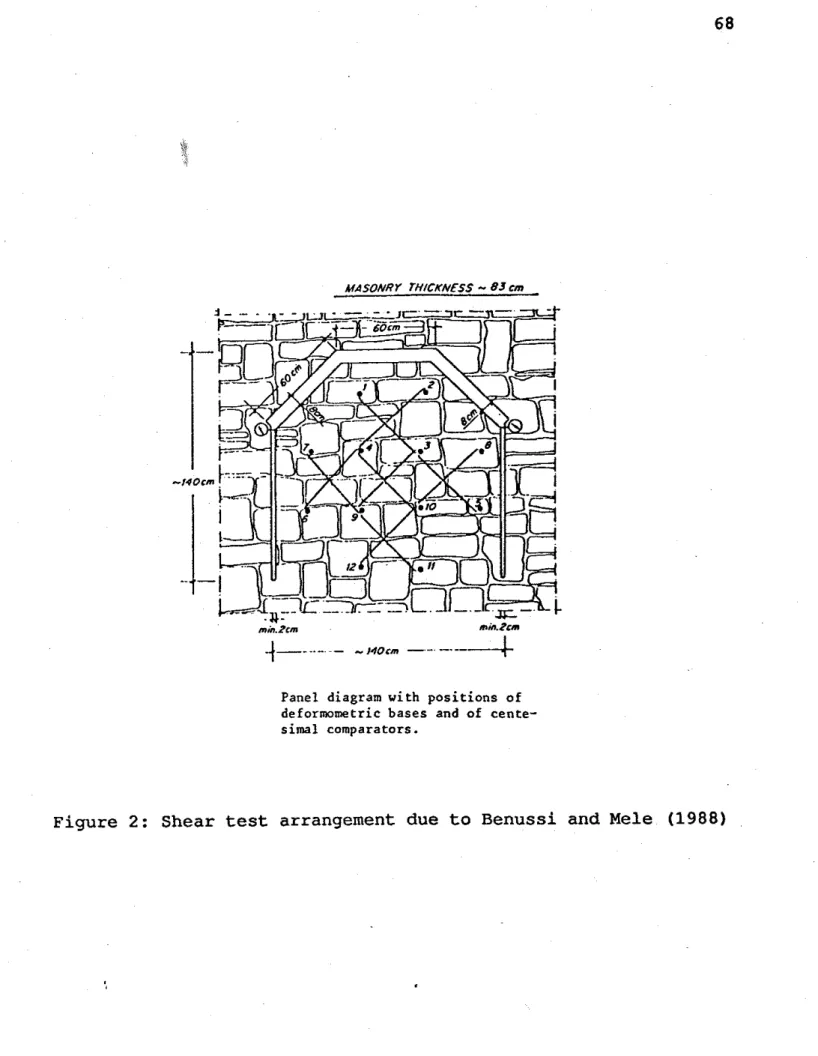
Benussi and Mele (1988) conducted,
"diagonal compression tests of a particularly arranged panel.
A portion of (stone) masonry is partially isolated with cuts,
whose width is the minimum to insert flat circular jacks, loading the panel in cyclic alternate stages. In all stages of the tests the diagonal compression was thrust as far as the beginning of the cracks, not to damage excessively the
structure. The deformations of the panel were read with
instruments, whose location is shown" (see Fig. 2).
Tomazevic and Anicic (1989), for the sliding shear test, removed units on both sides of the unit under test and placed an hydraulic jack in one gap formed. While reacting against the main body of the wall, the jack pushed the test unit into the other gap. The load to cause this represented the sliding shear resistance of the
masonry under its particular vertical load. Their paper also
included two results of (racking) shear tests. They commented upon the insufficiency of experimental data to enable correlation between shove and racking test results.
Using shove test results on four-wythe brickwork cut out of a 1917 brick building, Epperson and Abrams (1989) attempted to evaluate
racking shear wall strength. In the shove test, the tested unit
was pushed into the gap created by removing the head joint (or
perpend) on the end of the unit opposite to the jack. Some
difficulty was experienced in estimatingthe shearing area as there were some voids in the collar and bed joints. Further, as the bricks were frogged and there was no uniformity in orientation of the bricks so that the frog could be up or down, large differences in the mortar bedded areas were possible. This led to considerable
scatter in the shear stress plots. To obtain racking shear
strengths of five walls each subjected to a different level of vertical stress, calculations involving elementary principles of mechanics were used to convert shove test results to racking shear estimates. When the shove test data led to an overestimation of
the racking strengths by an average factor of 2.9, reduction
factors were incorporated so that shear strength estimates contained a margin of safety. There was still an overestimation by
an average factor of 1.5. Epperson and Abrams commented that the
overestimation "may be attributable to the (differences) in the observed modes of failure." The author agrees with this statement, although he would have expressed it more strongly, as the shove test mechanism involves only sliding along a brick-mortar interface whereas the racking test mechanism involves effects of shear in the bricks, flexural cracking, a complex shear stress distribution (a parabolic distribution was assumed by Epperson and Abrams), high compressive stress levels at the wall toe as well as brick-mortar interface sliding. The Epperson and Abrams conclusion is apt:
"Shear strength estimations may be improved by consideration of the mechanics of shear stress transfer indicated in the failure patterns observed for the test walls and a method measuring the diagonal tensile strength of the masonry." Laboratory tests examining horizontal bed joint shear failures and shear load-displacement behaviour of unreinforced brick masonry were conducted by Atkinson et a1 (1989). The tests were on old and new clay units, with different and appropriate mortars, and on field specimens collected from older brick walls damaged during the
" p r e v i o u s s t u d i e s on bed j o i n t s h e a r b e h a v i o u r , w h i l e p r o v i d i n g i n s i g h t i n t o p a r a m e t e r s i n f l u e n c i n g s h e a r s t r e n g t h , do n o t , i n g e n e r a l , p r o v i d e t h e d e t a i l e d i n f o r m a t i o n r e l a t e d t o c o n s t i t u t i v e b e h a v i o u r which would b e r e q u i r e d t o c o n s t r u c t a n a l y t i c a l models t o s i m u l a t e r e s p o n s e under r e a l i s t i c seismic l o a d i n g c o n d i t i o n s . Such a model w i l l r e q u i r e d e f i n i t i o n s o f
[and t h e i r a p p a r a t u s e n a b l e d t h e measurement]:
( a ) s h e a r s t i f f n e s s f o r b o t h i n i t i a l and r e p e a t e d l o a d i n g s t a t e s ;
( b ) peak and r e s i d u a l s t r e n g t h v a l u e s ;
( c ) normal l o a d and s t i f f n e s s e f f e c t s on s h e a r s t i f f n e s s and d i l a t a n c y ;
( d ) r e p e a t e d s h e a r r e v e r s a l s ; and ( e ) dynamic e f f e c t s . "
Atkinson e t a 1 found t h a t :
" I n g e n e r a l under c y c l i c s h e a r l o a d i n g , masonry bed j o i n t s show a peak s t r e n g t h f o r t h e f i r s t c y c l e f o l l o w e d by a r e s i d u a l s h e a r s t r e n g t h . Both peak and r e s i d u a l s h e a r s t r e n g t h s a r e w e l l r e p r e s e n t e d by t h e Mohr Coulomb c r i t e r i o n , w i t h f r i c t i o n c o e f f i c i e n t s r a n g i n g between 0.64 and 0.75 f o r t h e l a b o r a t o r y specimens. The f i e l d specimens show lower s h e a r s t r e n g t h v a l u e s . "
Shear t e s t r e s u l t s a r e n o t reproduced i n t h i s r e p o r t as t h e y a r e s o dependent upon t h e l e v e l of compressive stress on t h e specimen, whether s l i d i n g o r r a c k i n g s h e a r i s b e i n g d e t e r m i n e d . The compressive stress l e v e l i s n o t always r e c o r d e d i n t h e l i t e r a t u r e . Two e x c e p t i o n s a r e t h e r e p o r t s of Atkinson e t a 1 ( 1 9 8 9 ) , who a l s o g i v e a t a b l e of bed j o i n t s h e a r s t r e n g t h s o b t a i n e d by t h e m s e l v e s and o t h e r r e s e a r c h e r s , and of Epperson and Abrams ( 1 9 8 9 ) . I n b o t h p a p e r s s h e a r s t r e n g t h s , o b t a i n e d a t a number o f compressive stress
l e v e l s , a r e g i v e n .
2 . 6 Flexural Tests
A 10-year o l d b u i l d i n g , o f two-wythed brickwork, which w a s due f o r d e m o l i t i o n , had i t s w a l l s t e s t e d i n f l e x u r e ( l a t e r a l l o a d i n g t e s t ) by Hodgkinson e t a 1 ( 1 9 8 2 ) . Walls o f t h e 1 0 y e a r o l d brickwork had a mean s t r e n g t h i n t h e ' p a r a l l e l ' d i r e c t i o n ( i e c a u s i n g c r a c k s i n t h e h o r i z o n t a l m o r t a r b e d s ) h i g h e r t h a n t h e mean s t r e n g t h o f 'new' brickwork c o n s t r u c t e d w i t h s i m i l a r b r i c k s . The s t r e n g t h i n t h i s d i r e c t i o n i s a f u n c t i o n o f bond between b r i c k and m o r t a r s o t h e a u t h o r s commented "it i s t e m p t i n g t o f i n d h e r e e v i d e n c e f o r i n c r e a s e d bond w i t h age." I n t h e 'normal d i r e c t i o n 1 ( i e c a u s i n g
cracks in the vertical mortar joints or across units), the flexural strengths of 'old' and 'new' masonry walls were similar.
2.7 Mortar Bond Tests
Although the literature does not record any tests or results on old masonry for bond of mortar to the units, the equipment and procedure exists to enable such tests to be conducted in-situ. Hughes and Zsembury (1980) developed the 'bond wrench' which basically consists of a long lever one end of which is clamped to a masonry unit and an increasing load is applied to the other end. The moment of the load causing bond failure is a measure of the bond strength. There are now standardised bond wrench tests in the USA (ASTM 1986) and in Australia (SAA 1988). de Vekey (1991) and BRE (1991) reported a development of the bond wrench, the 'Brench',
which allows easier handling (of particular advantage when climbing
a ladder or scaffolding) and is safer as the operator holds the equipment throughout the test and at failure of bond the Brench moves in towards, rather than away from, the wall.
3. MATERIAL AND STRUCTURAL PROPERTIES BY INDIRECT TESTS
Overviews of indirect testing of masonry (often termed non- destructive testing) have been written by Noland et a1 (1983 and 1988), de Vekey (1988), Epperson and Abrams (1989), Rossi (1990)
and Maurenbrecher (1991)
.
It is useful to subdivide indirect tests into several categories: preliminary investigations, sonic and ultrasonic pulse velocity tests, radar method, thermographic analysis, strength of mortar by hardness measurement and monitoring.
3.1 Preliminary Investigations
Before determination ofthe mechanical properties of an old masonry structure, some background knowledge of the structure is needed.
Firstly the history of the construction is required. If at all
possible the original design and plans should be located. Photographs, sketches, reports and newspaper cuttings made at any time may be most useful as often it is found from these that the original structure was altered or strengthened in some way.
Secondly an accurate visual and geometric study of the structure must be made. The location and extent of cracks and other damage, the verticality and alignment of walls and towers, the change to a new material (eg a change of bricks or the use of a different stone) must all be known accurately in order that the current
integrity of the structure can be determined. A description and
be known. These investigations may involve conventional surveying, photogrammetry and photography.
Thirdly it is usually necessary to core drill small diameter holes to collect samples of wall cross sections to determine internal materials, bonding and number of wythes and chemical, physical and mechanical characteristics of the materials. Foundation material and size may be also determined by cores. A small video camera can be inserted into the core hole for further information on the
masonry composition and on internal cracks
-
see Modena et a1(1991).
Potter and Guant (1988) explained the use of precision electronic monitoring systems for the analysis and control of structures. In particular, foundation levels, wall and tower lateral displacements and cracks in historic structures were measured over an extended time period and the data analysed to determine trends and cyclic phenomena.
3.2 Sonic and Ultrasonic Pulse Velocity T e s t s
The testing technique is based on the generation, by mechanical impact or by electrodynamic or pneumatic transducers, of impulses at a point on the surface of a structure or in a bore hole. Receivers placed in various positions, on the same or opposite surface at different heights, collect the transmitted pulses. Measuring the time the impulse takes to travel in the material between the transmitter and the receiver and analysing the signal wave gives information on the material and/or the structure. For
sonic tests low frequency pulses in the range 0.5 to 10 kHz are
used whereas ultrasonic pulse frequencies generally lie in the
range 25 kHz to 1 MHz.
Epperson and Abrams (1989) studied sonic and ultrasonic wave velocity tests for their effectiveness in assessing condition and
in detecting uniformity of wall properties. They found that:
"sonic wave velocity tests showed less scatter of measured data than ultrasonic tests because of the longer wave length. Attenuation of the sonic waves was less than ultrasonic waves and the sonic wave velocities could be measured over distances as long as 10 feet [ 3 ml
."
Although various flaws and flawed regions were indicated by some of the results from both modes of transmission, the specific identification of the type of flaw was not possible.
By use of the sonic test method, Rossi (1990) stated that the following information could be obtained:
- estimate of the deformability modulus
- homogeneity of a structural element
- effect of grout or other strengthening
- presence of cracks in continuous materials.
With 'sonic tomography', which is the taking of some impulses along several directions to cover all of the section under investigation, a detailed map of the sonic velocity distribution on a plane section can be found. The technique has been used in concrete dams and on masonry pillars of a viaduct to determine areas where the material requires strengthening.
Binda et a1 (1982) refer to 'geophysical' techniques which depend, "on the correlation between the propagation velocity of acoustic waves within a material and its mechanical properties
( Young's modulus, Poisson's ratio). Geophysical methods can
be classified as active and passive. The former involve an acoustic excitation of the structure. The latter are based on the principle that cracks developing in the structure are always associated with the emission of elastic waves, which can be picked up at the surface: having at disposal a sufficient number of picking devices the emission point can be identified."
Because of the non-homogeneity and anisotropy of stone and brick masonry, "geophysical methods are better used in this case with the aim of characterizing materials in terms of signal propagation and modes, rather than in terms of dynamic modulus of elasticity". Direct velocity measurement tests of the active type on stone piers of a 16/17th century viaduct gave the following:
- components of maximum amplitude of signals received had
a frequency of 5000 Hz.
-
outside parts of pier of sandstone blocks (2500 - 3000m/s).
-
inside parts of pier of cohesionless materials (<2000-
m/s).
- sonic velocity diagrams revealed a discontinuity in one
pier, due to an additional structural part built up subsequently against one side.
The authors commented that sonic logging surveys can use core holes made in sampling and that it is possible to obtain sonic velocity diagrams by a plotter and "to directly correlate velocity, damping and frequency of sonic signals with the characteristics of the material crossed by the borehole".
Penelis et a1 (1983) conducted 600 'wide range hammer tests' on a brick monument and the results had a high correlation rate of 0.87
with results from compression tests of cores. While 300
'ultrasonic measurements' gave a very low correlation with compression test results, "very good correlation results,
concerning the dynamic modulus of elasticity, which is a quantity indispensable to the analysis as well as to the choice of the type of grout for the repair" were obtained.
Low frequency, 1 to 2 kHz, sonic investigations were used by Forde
et a1 (1987A) to monitor the quality of brickwork and the thicknesses of old masonry bridge abutments, Forde et a1 (1987B) to study the quality of brickwork bridge piers and Birjandi et a1 (1984) to successfully locate the position of cracks in brick walls previously failed in shear.
Berra et a1 (1987) investigated ultrasonic pulse transmission to evaluate grout strengthening of brick masonry prisms.
3 . 3 Radar Method
Rossi (1990) described the method as follows:
"The radar testing technique uses high-frequency electro-
magnetic waves (100 MHz
-
1 GHz) emitted through an antennawith very short impulses (0.5
-
5 s and permits us todetermine location of separate surfaces between materials with different dielectric constants. The investigation is based on reflection (the reflected waves from the contact surfaces between materials of different dielectric constants are received through an antenna and are transformed into electric signals) so internal defects in the masonry (damp areas, cavities, presence of metal structures, piping, flues) can be
located.
. . .
Recently the radar technique has been used on thearches which support the roof of the Cathedral in Parma to determine the position of the joints between blocks of stone that are covered by a fresco."
McCavitt and Forde (1991) successfully used 'ground probing radar' in the investigation of the internal structure of old masonry arch bridges.
3 . 4 Thennographic Analysis
Based on the thermal conductivity of the material, thermographic analysis may be passive, such as natural cycles of thermal stress due to insulation and subsequent cooling, or active, where forced heating is applied, according to Rossi (1990). "Thermal radiation is collected by apparatus sensitive to infrared radiation, and is then transformed into electric signals, which in turn are converted
into images in different shades of colour." It can distinguish
between areas of different material or moisture content.
While the penetration depth of this technique is only a few centimetres, it may be used advantageously on walls covered with plaster which may hide construction details such as blocked openings, flues, ducts and pipes.
3.5 Mortar Strength from Hardness Measurement
The importance of finding the mortar compressive strength in old masonry was discussed in Section 2.2. As it is difficult to get a direct measurement of the compressive strength of existing mortar, non-destructive methods for mortar may be crucial.
Pume (1989) gave a method for mortar compressive strength estimation in which a hand drill was modified with percussion and an impact counter. The depth of penetration into a mortar bed of
an 8 mm diameter drill after 10 impacts at 150 N force was measured
and the mortar strength calculated from an empirical formula. Pume (1991) used the results in an empirical formula to estimate the compressive strength of the mortar and, with the compressive strength of the bricks, he then estimated the compressive strength
of the masonry - see Section 2.1.6.
Another method for mortar compressive strength estimation is given
by Pume (1989). The number of impacts of a 4 mm diameter
cylindrical indentor, each with an energy of 1 Joule, to drive the indentor 5 mm into the mortar is related to the compressive strength of the mortar.
A modification of the Schmidt pendulum hammer for plaster and aerated concrete has been developed by van der Klugt (1991) to measure the hardness of pointing in masonry. This apparatus gives an accurate measure of hardness as opposed to the crude assessment given by the traditional scratching of mortar with a knife, screwdriver or car keys!
3.6 Monitoring
Measuring instruments installed in a building to monitor its behaviour over time can produce results of importance.
Rossi (1990) reported that the principal features which were monitored in Italy and the methods of measurement used were:
- openings of the main cracks in masonry structures, using
removable mechanical extensometers or fixedextensometers
with electric transducers connected to an automatic data collection system;
- absolute horizontal movements of vertical structures,
using a fixed pendulum with a measuring system based on
a 'tele-coordinometer'
-
presumably a theodolite;- relative horizontal movements of vertical structures,
using a long base extensometer equipped with an invar wire kept in tension with a weight and the movement of the weight measured by electric transducers;
-
rotation of horizontal and vertical structures, using fixed or removable clinometers;- internal and external temperature
-
behaviour of soil and rock foundations.Rossi cited six buildings and monuments of importance in Italy, including the Milan Cathedral, which were being monitored.
4. DYNAMIC TESTS
A model of a single-storey stone masonry building, at a 1:5 scale,
was built and tested on a laboratory shaking table by Turnsek et a1 (1978).
" The results of laboratory tests of the strengthening of
stone masonry walls and buildings, together with methods developed for calculating the shear resistance of masonry buildings, have been verified on actual buildings which stood in an area where the two successive earthquakes of May and
September 1976 were of a similar strong intensity (the village
of Lusevera in Friuli)
."
Tomazevic and Anicic (1989) commented on these tests as follows: "Although plain masonry is considered as a brittle material, even old masonry buildings possess a relatively high energy
absorption capacity. As indicated by the analysis of
earthquake
-
damaged buildings, the shaking table tests haveshown that, when damaged during a strong earthquake, the dynamic characteristics of these buildings change, which results in a much lower level of effective seismic loads than expected theoretically."
As the model became more damaged with larger ground acceleration so
the dynamic amplification factor reduced from 3.7 to 1.2.
Tomazevic and Sheppard (1982) conducted shaking tests on laboratory-made specimens, of limestone blocks with mortars equivalent to the lime mortars of old rural houses and public
buildings which had been in an earthquake. Those specimens
reflecting rural houses, with uncoursed stone and low quality mortars of clayey sand and earth, had ductility ratios of 8.2; those with clean sand lime mortars of compressive strength between
0.5 and 1.0 MPa had ductility ratios between 9.0 and 10.7; those reflecting public buildings with partly coursed stone and clean sand lime mortars of compressive strength 1.0 MPa had ductility ratios between 4.7 and 7.3.
In Yugoslavia, UNESCO (1982 and 1983) reported that more than 70 buildings were subjected to forced vibrations using low excitation forces in the elastic range to determine dynamic characteristics ie natural frequencies, modes and damping coefficients. While some of these buildings were of brick masonry, it is not known whether they
were of old masonry. On some buildings, the forced vibration
testing focused on some special effects:
-
influence of non-structural components (eg claddingwalls) on building stiffness, by testing the building before and after the construction of such walls;
- effect of floor diaphragm stiffness, in its own plane, on
the distribution of forces to individual vertical structural components;
- effect of horizontal asymmetry on the occurrence of
torsional oscillations;
- effect of soil-structure interaction;
-
effect of inadequately spaced earthquake expansionjoints.
The natural period of vibration of a brick monument was found by Penelis et a1 (1983) by test to be 0.42 sec and estimated by analysis to be between 0.33 and 0.53 sec. The authors indicated that forced vibration measurements were underway.
Tomazevic and Anicic (1989) reported:
"Ambient vibration tests of two typical old stone masonry buildings in the historic centre of the city of Ljubljana, Yugoslavia have indicated almost the same values of
fundamental frequencies (4.2 and 4.6 Hz respectively),
although the two buildings were different in plan and
elevation. Similar conclusions can be drawn from ambient
vibration tests of several monumental buildings in the city of Dubrovnik and also from ambient vibration tests of post-war multi-storey masonry buildings in Ljubljana."
Dynamic parameters such as natural frequencies, modal shapes and damping ratios can be evaluated, according to Rossi (1990), through spectral analysis of data gathered as a response to dynamic loads 'naturally' applied to structures such as road and rail traffic vibrating the structure through the foundation and the ringing of
bells. Forced vibration tests, of low intensity so that the
vibrations do not affect structural integrity, with the recording and analysis of the displacement, velocity and acceleration response of the system can also supply the dynamic modal parameters. With these parameters the structural response to any type of dynamic load and the seismic vulnerability of old masonry
buildings, can be computed. Rossi reported that the forced vibration technique, together with flat jack tests, enabled the discovery of some structural weaknesses in some towers in Pavia, Italy.
Modena et a1 (1991) measured the ambient vibrations at the top of an old stone masonry tower and used the results in a numerical model analysis.
Two seismic diagnostic techniques were reported by Stockbridge and Crist (1988). In the first, the condition of an historic structure is evaluated by performing a random decrement analysis to develop a baseline response signature. This signature can then be used for comparison with a signature taken after an earthquake to assist in
identifying internal damage. The initial displacement, in the
signal processing technique of random decrement analysis, is normally induced by wind or other random forces, such as vehicular traffic, and the response of the building is measured with a seismometer held in contact with the building and appropriately
oriented. The second technique involves the installation of
recording accelerographs in the historic building. The record
after an earthquake enables the evaluation of the potential for damage in future earthquakes.
5. MODELLING OF OLD MASONRY 5.1 Static Modelling
Binda et a1 (1991) derived simple mathematical models to determine the load distribution between the wythes of multi-wythe masonry walls in two different limit situations. In the first the wythes were so connected by stiff elements that the load was transferred
to the wythes as their axial stiffnesses. In the second the wythes
were only connected by collar joints or by the mortar of the rubble filling so that the load distribution was mainly dependent on the bond strengths between the wythes.
5.2 Dynamic Modelling
A full investigation into the literature pertaining to dynamic
modelling of old masonry is beyond the scope of this report. Further the area has been covered by Bruneau and Boussabah (1991). However there are papers in the area which have been published since the Bruneau and Boussabah report and they are reported below. Calvi and Magenes (1991) conducted the first phase of an experimental evaluation of seismic strength of old masonry structures:
"The experimental testing of masonry elements is the only viable method to investigate the conditions under which
different events may take place, and to quantify the variation
of the basic mechanical properties. Only on this basis
rational and effective numerical models could be developed." The authors considered four possible limit states:
-
flexural cracking, which does not involve collapse butdetermines a variation of the stiffness and the formation of hysteresis loops,
- flexural strength (rocking and toe crushing)
- shear diagonal cracking, which is not an ultimate limit
state if only one direction of loading is considered and if sufficient friction is developed in the cracks, but it might cause an out-of-plane failure.
- shear sliding, which has to be considered as an ultimate
limit state even if, in principle, it does not always involve a significant reduction in the load carrying capacity of the panel.
Compression, tension and shear tests were conducted on specimens of mortar, brick units and triplets which were built with materials
which could simulate historical materials closely. Full scale
panel tests were still in progress at the time of the publication of the paper.
The English abstract to the paper of Baggio and Masiani (1991), written in Italian, stated:
"In a previous work a simplified dynamic model was developed, based on the idea that the collapse of masonry structures does not occur because of the exceeding of a limit strength, but because of the loss of equilibrium due to the formation of a mechanism of rigid bodies, as often observed in actual buildings under seismic action. To check the effectiveness of such an approach experimental work is strongly needed. In this paper some results of preliminary experimental tests on simple models under harmonic excitation are shown and discussed. Results fairly agreed with the theoretical model."
6. FIELD PERFORMANCE OF OLD STONE AND BRICK BUILDINGS IN EARTHQUAKES
In a general paper on earthquake damage to historic masonry buildings, Balderrama (1990) stated:
"Masonry is brittle. It has a high mass and, therefore, a
high inertial response to earthquakes. It is rigid and has low tensile and shear strengths, little ductility and a low
capacity for bearing reversal loads and the redistribution of
stresses. In general, masonry structures are designed for
static conditions and do not conform to the elastic theory. From a limited viewpoint, the characteristics of historic buildings are disadvantageous to earthquake resistance. The poor performance of some forms of masonry has resulted in cautious attitudes that presume the inferiority of masonry
materials and forms of construction. There are, however,
several observations that contradict such a presumption. Firstly, very little research has been done into the seismic response of masonry structures, whether reinforced or unreinforced, with or without a built-in frame. Most of the available knowledge is based largely on inferences from static loading tests.
Secondly, field observations seldom mention the relationship between construction quality and the seismic structural performance of masonry buildings. Evidence has shown that there is a direct link between good quality construction and minimum damage. If properly used, masonry construction can
have a reasonable resistance to earthquake movements. A
common fallacy in field observations after earthquakes is the assumption that the performance of materials and structures is due to their inherent qualities. It is often assumed that certain materials are, in themselves, either good or bad, durable or non-durable, resistant or non-resistant, strong or
weak. In reality, these properties are relative and vary
according to the conditions of exposure of the structure, the level of its loading and its capacity to re-distribute stresses, amongst other factors.
Historic buildings are not necessarily weak because they are
old, or have been built with masonry. Some historic
buildings, like some modern buildings, are weak because they are poorly constructed, or are subjected to abnormal stresses."
The author agrees with the Balderrama thesis that it is incorrect to assume that, simply because a structure is built of unreinforced masonry and therefore of low ductility, its performance in an earthquake will always be disastrous. This fallacious attitude is apparent in many of the reports on earthquake damage which follow. And it is apparent that many old masonry buildings have survived
severe earthquakes. As Baldarrama points out those buildings that have failed have usually been poorly constructed or subjected to abnormal or unusual 'loadings' rather than because of an inherently
weak material. Poor structural layout can also contribute to
premature failure. The author has attempted to keep these points in mind in his reporting of the literature on earthquake damage.