Publisher’s version / Version de l'éditeur:
Canadian Journal of Civil Engineering, 14, 4, pp. 447-454, 1987-08
READ THESE TERMS AND CONDITIONS CAREFULLY BEFORE USING THIS WEBSITE. https://nrc-publications.canada.ca/eng/copyright
Vous avez des questions? Nous pouvons vous aider. Pour communiquer directement avec un auteur, consultez la première page de la revue dans laquelle son article a été publié afin de trouver ses coordonnées. Si vous n’arrivez pas à les repérer, communiquez avec nous à PublicationsArchive-ArchivesPublications@nrc-cnrc.gc.ca.
Questions? Contact the NRC Publications Archive team at
PublicationsArchive-ArchivesPublications@nrc-cnrc.gc.ca. If you wish to email the authors directly, please see the first page of the publication for their contact information.
NRC Publications Archive
Archives des publications du CNRC
This publication could be one of several versions: author’s original, accepted manuscript or the publisher’s version. / La version de cette publication peut être l’une des suivantes : la version prépublication de l’auteur, la version acceptée du manuscrit ou la version de l’éditeur.
Access and use of this website and the material on it are subject to the Terms and Conditions set forth at
Force reduction factors for the seismic provisions of the National
Building Code of Canada
Rainer, J. H.
https://publications-cnrc.canada.ca/fra/droits
L’accès à ce site Web et l’utilisation de son contenu sont assujettis aux conditions présentées dans le site LISEZ CES CONDITIONS ATTENTIVEMENT AVANT D’UTILISER CE SITE WEB.
NRC Publications Record / Notice d'Archives des publications de CNRC:
https://nrc-publications.canada.ca/eng/view/object/?id=8ca60b02-0b99-4351-af1b-0943cffbb1a4 https://publications-cnrc.canada.ca/fra/voir/objet/?id=8ca60b02-0b99-4351-af1b-0943cffbb1a4
S e r
TH1
N21d
Natlonal Research
Consell natlonal
no.1519
CI
c
ouncil Canada
de recherches Canada
c. 2
BLDG
Institute for
lnstitut de
\ - - -
Research in
recherche en
Construction
construction
Force Reduction Factors for the Seismic
Provisions of the National Building Code
of Canada
by
J.H. Rainer
J
Reprinted from
Canadian Journal of Civil Engineering
Vol.
14,
No.
4,
Aug.
1987
p.
447-454
(IRC Paper No.
1519)
Price
$3.00
NRCC
28773
I
B I B L I O T H ~ Q U E
I R C
T h i s p a p e r i s b e i n g d i s t r i b u t e d i n r e p r i n t f o r m by t h e I n s t i t u t e f o r R e s e a r c h i n C o n s t r u c t i o n . A l i s t of b u i l d i n g p r a c t i c e and r e s e a r c h p u b l i c a t i o n s a v a i l a b l e from t h e I n s t i t u t e may be o b t a i n e d by w r i t i n g t o t h e P u b l i c a t i o n s S e c t i o n , I n s t i t u t e f o r R e s e a r c h i n C o n s t r u c t i o n , N a t i o n a l R e s e a r c h C o u n c i l of C a n a d a , O t t a w a , O n t a r i o ,
KlA
0R6. Ce document e s t d i s t r i b u g s o u s f orme d e t i r e - 3 - p a r t p a r 1 ' I n s t i t u t de r e c h e r c h e e n c o n s t r u c t i o n . On p e u t o b t e n i r une l i s t e d e s p u b l i c a t i o n s - d e 1 ' I n s t i r l l t n n r + a n L s u r l e s \ye d e s PUn
c
(e
r~
Id
- - - - -. - --
Force reduction factors for the seismic provisions of the National Building Code of Canada
J. H. RAINER
Institute for Research in Construction, National Research Council of Canada, Ottawa, Ont., Canada KIA OR6 Received July 31 , 1986
Revised manuscript accepted February 17, 1987
A derivation of force reduction factors for the seismic provisions of the National Building Code of Canada (NBCC), 1985, is presented. This includes the following: classification of seismic actions, applicable limit states, change in load factor, derivation of force reduction factors, and classification of structural configurations. Quantitative comparisons are made between the derived force reduction factors and the response modification factors of the Applied Technology Council and good agreement was found. It is suggested that seismic requirements should be considered as accidental actions with a load factor
a, = 1.0. These results can form the basis for possible modifications to the 1985 NBCC seismic provisions. Key words: earthquake resistant structures, building code, loads, load factors.
Une dCrivation des facteurs de rkduction de la force pour fes exigences du Code national du bltiment (1985) relatives aux sCismes est prCsentCe. Ceci inclut : classification de I'activitC sismique, Ctats limites applicables, modification du coefficient de charge, dCrivation des facteurs de rkduction de la force et classification des configurations des structures. Des comparaisons quantitatives sont effectuCes entre les facteurs de rkduction de la force dCrivCs et les facteurs de modification de la rCponse proposCs par le Applied Technology Council, et on a constat6 une bonne correspondance entre les deux. L'auteur suggbre de considCrer les exigences relatives aux sCismes comme des Cvtnements accidentels avec un coefficient de c x ~ = 1.0. Ces rksultats peuvent servir de base k des modifications possibles des exigences du Code national du bltiment (1985) relatives aux sCismes.
Mots clks: structures rksistant aux tremblements de terre, code du bltiment, charges, coefficient de charge. [Traduit par la revue]
Can. J. Civ. Eng. 14,447-454 (1987)
1. Introduction
The objective of the seismic provisions of the National Building Code of Canada (NBCC 1 9 8 5 ~ ) is to protect the occupants of buildings from the destructive effects of earth- quakes. This is achieved by specifying design loads and detail- ing requirements so that the probability of building collapsing or injuring people is acceptably low when the structure is subjected to a certain level of ground motion. At the same time it is admitted that the building or portions of it may sustain minor or major damage (NBCC 1985b). Code requirements for achieving such seismic resistant characteristics of buildings have evolved in a semiempirical manner by simplified mathe- matical and experimental models and from experience of the behaviour of structures in earthquakes. A history of the development of the NBCC seismic provisions has been pre- sented by Uzumeri et al. (1978). Because of the semiempirical development of the code, the basis for some of the loading requirements are sometimes obscured to the user. This tends to impede the rational application of the provisions to specific problems, particularly nonstandard ones, and slows the pro- gress in improving code provisions in light of new research results.
Significant steps toward a rationalization of the NBCC seis- mic provisions were taken in the 1970 edition when a seismic risk map based on probabilistic principles was introduced. Also an explicit ground acceleration parameter A was incorpo- rated into the base shear calculation. Further rationalization occurred in 1985 when two ground motion parameters, accel- eration and velocity, were adopted, resulting in a seismic response factor S that varies with the applicable velocity and acceleration zones 2, and Z, (Heidebrecht et al. 1983; Heidebrecht and Tso 1985). In the following presentation,
NOTE: Written discussion of this paper is welcomed and will be received by the Editor until November 30, 1987 (address inside front cover).
further possible improvements in the seismic design require- ments of the NBCC are suggested. These topics are currently under consideration by the Canadian Committee on Earth- quake Engineering (CANCEE). Before commencing with detailed considerations of seismic resistant design require- ments, however, it is desirable to examine how the seismic phenomenon is treated by the building code.
The natural phenomenon that is to be addressed in seismic design is the ground motion at a given location as a result of a seismic event at some distance. This ground motion is given in terms of displacement, velocity, or acceleration and is termed the "action" (CSA 198 1 ; I S 0 1984). For code purposes, the action corresponds to the design ground acceleration or velocity, or related coefficients, which are obtained from seis- mic risk maps that are derived from a statistical evaluation of historical and geological data corresponding to a small proba- bility of exceedance per annum. This seismic action is inde- pendent of any structure to be considered.
The building to be built at a particular location has to be designed to resist this action. Since the seismic events implied by the specified seismic action occur infrequently, nonlinear material behaviour is accepted, nay encouraged, thereby reducing member sizes. A trade-off is thus made between ductile structural behaviour and accompanying damage and the initial cost of the structure.
The reader will no doubt ask "Why are the seismic design forces not actions?" These forces are not basic loading condi- tions but are derived from the ground motions to represent roughly the inertia forces induced in a structure by the postu- lated or specified seismic action. While the specified action is constant at a particular location, greatly different seismic design forces are obtained for the same structures depending on the degree of ductility assumed and provided for in the design. Thus it is the ground motions that are the basic seismic actions and not the forces derived from a dynamic analysis o r those prescribed in a building code.
448 CAN. J . CIV, ENG. VOL. 14. 1987 2. Classification of seismic actions
The traditional manner of achieving seismic resistant design of structures has been to determine an equivalent static lateral load which is deemed to represent the dynamic loading effects of the earthquake, and then to design the structure to resist these forces. In the design process, the resulting seismic forces have generally been treated in the same way as wind loads, and are together called "lateral loads." They have been assigned a common load factor a = 1.5 (NBCC 1 9 8 5 ~ ) . There are a number of reasons, however, for differentiating between wind and seismic loads in Canada and in other of the world where similar hazards of these natural phenomena exist:
(1) The frequency of occurrence of high winds correspond- ing to the specified design loads is greater than that for earth- quakes. This is reflected in the return periods of 30 years for the design wind speed, whereas it is 475 years for the estab- lishment of the seismic risk maDs (NBCC 1985b). L ..
(2) The statistical behaviour of the two phenomena is quite different. In terms of a plot of amplitude versus probability of exceedance (or return period), the wind speeds start to level off around the 30-year return period whereas the seismic action keeps rising and begins to level off in the order of a few hundred years return period (Ferahian 1971).
(3) Because seismic design forces are large but relatively infrequent, the conscious decision is made - and is incorpo- rated in the seismic code requirements - that large cyclic inelastic deformations are permitted so long as the structure does not collapse. Wind forces, on the other hand, are usually resisted elastically.
While the probability of occurrence of the specified seismic action is small during the life of the structure, it is nevertheless large enough so that it has to be considered as an environmen- tal action. Therefore the structure is designed according to the ultimate limit state and, under these conditions, is considered to be on the verge of collapse. It can thus be argued that the seismic action pertaining to seismic resistant design of build- ings should correspond to an "accidental action." As there is no further "factor of safety" required, the load factor associ- ated with these seismic actions should therefore be 1 .O.
For wind action the design load may be reached once or a few times duridg the life of the structure. It is therefore a "variable action" in the International Standard Organization (ISO) terminology and should have a load factor that reflects the relatively high probability that this load can be exceeded; consequently a = 1.5 is used. Design conditions that could be compared to earthquakes are tornados. These could also be considered as accidental actions, for which the ultimate limit state and ~ossiblv a load factor of 1.0 would be indicated. The distinction between wind and seismic actions presented above corresponds generally to the description of variable actions and accidental actions, respectively, contained in the Guidelines for Development of Limit States Design (CSA 1981) and in ISO/DIS 2394 (IS0 1984). However, in the CSA document, earthquake loads are listed together with wind under "live loads" or variable actions. This may be due to historical reasons. Also, the seismic zoning in effect in 1981 was based on a 100 year return period and could therefore be viewed more like a variable action. With the zoning map for 1985 NBCC based on a return period of 475 years, however, seismic action now corresponds more clearly to an accidental event.
It is instructive to examine the approach taken by the Jap- anese seismic code for buildings (Ishiyama 1985). The seismic
design loads are specified for two levels: (1) For moderate earthquakes a shear coefficient Co of 0.2 is given correspond- ing to ground motions that can be expected a few times during the life of the building. The design for this specified loading is to be carried out elastically and under such an earthquake the building would be expected to sustain little or no damage. (2) For a major earthquake, Co = 1 .O is prescribed, for which the calculation and verification of the ultimate lateral shear strength is required. Nonlinear ductile behaviour and increased damping values can be utilized. Thus the Japanese code in effect specifies both a frequent (variable) and an infrequent (accidental) action, whereas the NBCC only prescribes what amounts to an accidental one.
3. Limit states
The limit states applicable to seismic resistant design are the ultimate limit states concerning safety, and the serviceability limit states which concern restriction of normal use and occu- pancy and durability (CSA 1981; I S 0 1984; Allen 1982). The overwhelming preoccupation of earthquake engineering in the past has been with the prevention of collapse of structures, i.e., the ultimate limit state. There are, however, situations where the serviceability limit state is also of interest. This occurs when continuation of the function or preservation of the contents of a building during and after an earthquake is impor- tant. Examples are hospitals, communications facilities and other "life-lines," and important military installations. There may also be economic reasons for trying to achieve a certain level of serviceability as, for example, in a factory, an office building, or buildings housing precious objects; it may be desired to reduce potential losses of function, investment, production, or irreplaceable artifacts.
Whereas the ultimate limit state is reasonably well defined in terms of prevention of collapse, the serviceability limit state needs to be specified in terms of the desired result that is to be achieved. Such serviceability limit states could be: no major cracking, i.e., no inelastic deformation; a limit on maximum interstorey deformation in order to reduce damage to architec- tural finishes or components; or a limit on the maximum tolerable acceleration in the building. To achieve these objec- tives different design decisions would have to be taken. For most cases of serviceability, however, a knowledge of what constitutes the load level corresponding to the elastic limit and the degree of nonlinear deformation implicit in the design forces needs to be clarified. The following treatment of force reduction factors will facilitate this determination of load lev- els that correspond to the elastic limit of structural behaviour.
4. Relationship between K-factors and force reduction factors
The design forces specified in building codes are consider- ably smaller than the levels corresponding to elastic structural response that results from the given seismic actions. In the NBCC (1985a, b) the force level is a function of K-factors, with an additional overall scaling factor contained in the expression for the seismic response factor S. The K-factors are merely a means of assigning relative merit to different struc- tural systems on the basis of observed or expected behaviour in earthquakes; their numerical values have no absolute rational interpretation. The K-factors can be related, however, to the expected plastic behaviour of a structure and the correspond- ingly lower forces required during the dynamic response to
D U C T I L I T Y R A T I O
P = A ~ / A
B E H A V I O U R
A A , D E F O R M A T I O N
FIG. I
.
Force-deformation relation for simple elastic-plastic systems.RAINER 449
useful to calculate the elastic load level V , that corresponds to the specified seismic action, and then to apply a force reduc- tion factor R:
Here,
S
is an elastic response spectrum similar to but larger than S in [I]. The numerator represents the base shear of the elastic response and R in the denominator accounts for the force reduction on account of ductile behaviour of elastic-plastic systems and (or) increased damping. This is the format em- ployed by the Applied Technology Council seismic code rec- ommendations (ATC-3 1978). For calibration purposes, the case is chosen for which the velocity seismic zone is equal to the acceleration seismic zone, i.e., Z , = Z ,.
This represents an average condition throughout the country.To find the relationship between the currently used K-factors and the corresponding force reduction factors R , [ l ] and [2] are equated, so that
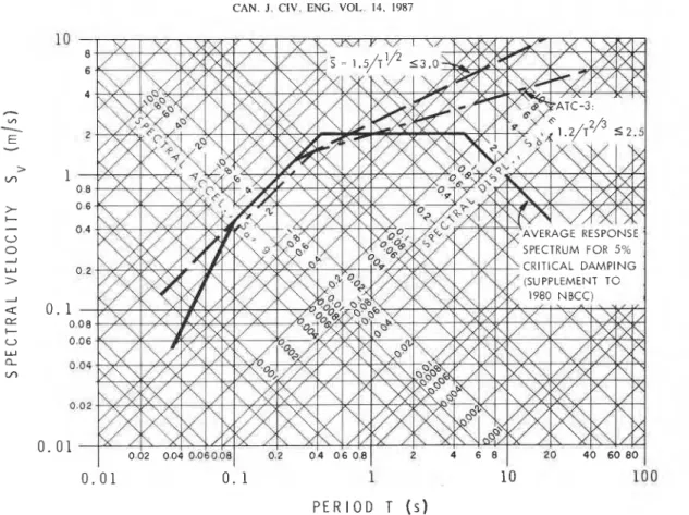
As is taken to represent an elastic response spectrum for a single-degree-of-freedom oscillator, it will need to have an upper bound of 3.0 in the low-period range corresponding to the amplification factor 3.0 applicable to the acceleration por- tion of response spectra for 5% critical damping (Newark
et al. 1973). In the 1985 NBCC, S = 0 . 2 2 / ~ " ~ < 0.44 (Fig. 2); this expression has to be scaled so that = 1 .5/T'I2
S 3.0, in order that the bounding value 3.0 be equal to the elastic amplification factor in the short-period region. Thus [3] becomes
0 0. 2 5 0 . 5 0 0 . 75 1 . 0 0 1. 25
[4] 0.22K = 1.51R P E R I O D T ( s )
FIG. 2. Seismic response factor S for the 1985 NBCC. [5] R = 6.8lK seismic ground motions. As such, these factors are an indicator
of a "system ductility" - not to be confused with "member ductility." Although system ductility for multistorey structures cannot yet be defined simply, the notion is useful in qualitative terms and can be applied quantitatively to single-degree-of- freedom (SDOF) oscillators. Reference to the SDOF oscillator has to be made until such time that a simple quantitative definition for more complex structures becomes available.
The K-factors in the NBCC (1985a, b) are usedias multi- pliers in the calculation of base shear V:
This results in the following correspondence between K for the 1985 NBCC and the force reducxtion factor R of [2]:
K-factor Derived (1985 NBCC) force reduction factor R
where v = zonal velocity ratio; S = seismic response factor for the structure (see Fig. 2); 1 = importance factor; F = foundation factor; W = dead load plus some live or storage loads; and K = factor related to structural behaviour.
The base shear V thus calculated assumes a certain level of ductile behaviour in the structure and corresponds to the yield level required for the seismic response of the structure. This is shown diagrammatically in Fig. 1. If the structure were to remain elastic, a much higher elastic capacity V, would be required. The difference between these two force levels needs to be provided by the ductile behaviour of the structure and its members.
While it is not usually practical to design a structure to remain elastic under severe seismic loading, it is nevertheless
The above result shows that in order to achieve elastic behav- iour against the ground motions that are implied by the building code, the specified code forces would have to be multiplied by R corresponding to the applicable K-factors listed above.
The correspondence between K and R has been established assuming that identical load factors apply to both calculations. This load factor is aQ = 1.5 specified in the 1985 NBCC for service loads and other environmental loads such as wind and earthquakes. As was pointed out, however, there are strong arguments for treating the specified seismic effects in the building code as accidental actions for which the load factor % should be 1 .O. For the ultimate seismic loads to remain constant and changing IXQ from 1.5 to 1.0 requires dividing the R-values
CAN. J. CIV. ENG. VOL. 14. 1987 I
FIG. 3. Normalized average response spectrum and design seismic response factors. K-factor Force reduction factor R
(aQ = 1.5) (aQ = 1 .O)
The above derivation of R is merely a change in format from [I] to [2], and does not involve a change in seismic design forces or seismic resistance of buildings. The advantages of this new format will be discussed later.
Just as the K-factor in the 1985 NBCC is a measure of the ductility of the structure, so is the proposed R-factor but in the inverse ratio. Increasing values of R generally denote greater structural ductilities, but a simple quantitative relationship for multi-degree-of-freedom structures is currently not available.
5. Comparison of K and R of NBCC and ATC-3
With aa equal to 1.0 there is now a consistent basis for comparing the "response modification factors"
R,'
suggested by the Applied Technology Council (ATC-3 1978), since it also uses a = 1.0 as a load factor. For comparable conditions, however, ATC-3 employs the relationship l.2/TZf3 =Z 2.5 rather than the scaledS
= 1 . 5 / ~ ' / ' 3.0. This is shown in Fig. 3, and in the short- and medium-period range amounts to a difference of about 20%. This difference will not be utilized '~lthough the symbol R is used in ATC-3,R
will be used here for clarity.in the subsequent comparison, but could of course be applied to the final result if this were desired. -
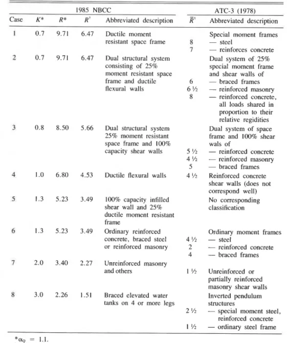
The comparison between K, R , and R is shown in Table 1, where the structural types in NBCC and ATC-3 have been matched in the most suitable manner. The derived R's for the NBCC and the R's of ATC-3 show good agreement in general. The largest discrepancies occur for case 1, the most ductile category, for which ATC-3 gives higher values, and cate- gory 7, unreinforced masonry or other structural categories, for which ATC-3 gives a lower rating than 1985 NBCC.
6. Classification of structural systems and K-factors
In the seismic provisions of the National Building Code of Canada (and similarly of the Structural Engineers Association of California (SEAOC 1980) and the Uniform Building Code (UBC 1985)), various structural systems are assigned relative values of K, where K is defined in the NBCC 1985 as "numerical coefficient that reflects the material and type of construction, damping, ductility and (or) energy-absorptive capacity of the structure as given in Sentence . . ." Although the table for K in the 1985 NBCC appears at first sight without any inherent rationale, the following grouping can be dis- cerned: (1) primary structural forms; (2) combined systems; and (3) special or sensitive structural forms.
(I) Primary structural forms: These consist of the following structural types with the associated K-factors: (a) Ductile frame, K = 0.7; (b) Ductile flexural wall (ductile reinforced concrete, K-braced or tension-compression braced frames), K = 1.0; (c) Regular shear wall (infill frame, reinforced masonry, regular reinforced concrete), K = 1.3; and (d) Cross-braced frames (tension-tension system), K = 1.3.
( 2 ) Combined systems: These are structural forms that con-
RAINER
TABLE 1. Comparison fo K of 1985 NBCC, derived R, of ATC-3
1985 NBCC ATC-3 (1978)
Case K* R* R' Abbreviated description Ei Abbreviated description Ductile moment
resistant space frame
Special moment frames
- steel
- reinforces concrete
Dual system of 25%
special moment frame and shear walls of
- braced frames - reinforced masonry
- reinforced concrete, all loads shared in proportion to their relative regidities Dual system of space frame and 100% shear wals of
- reinforced concrete
- reinforced masonry
- braced frames
Reinforced concrete shear walls (does not correspond well) No corresponding classification Dual structural system
consisting of 25% moment resistant space frame and ductile flexural walls
Dual structural system
25% moment resistant space frame and 100% capacity shear walls
Ductile flexural walls
100% capacity infilled shear wall and 25% ductile moment resistant frame
Ordinary reinforced concrete, braced steel or reinforced masonry
Ordinary moment frames
- steel
- reinforced concrete
- braced frames Unreinforced masonry
and others Unreinforced or
partially reinforced masonry shear walls Inverted pendulum structures
- special moment steel, reinforced concrete
- ordinary steel frame Braced elevated water
tanks on 4 or more legs
system by themselves. Their combined action under major seismic motion is considered to be beneficial on account of increased redundancy, and aIso because of the notion of a
with those that correspond to the principal element. This grouping is illustrated in Fig. 4.
backup system in case the major load-resisting element fails. These combined systems include the following, with the applicable K-factors and reference to above primary systems
7. Suggested modifications of NBCC seismic
requirements
given in parentheses: (a) flexural wall (lb), together with an interactive ductile frame (la), K = 0.7; (b) regular shear wall (lc) or braced frame (Id), together with ductile frame (la) (100% V taken by wall, 25% by ductile frame), K = 0.8. (3) Special or sensitive structural forms: This includes struc- tural systems not included above: (a) all others not included
The above considerations and comparisons indicated three main areas in which the seismic requirements of the NBCC could be modified: (a) load factors for earthquake loads; (b) assignment of force reduction factors; and (c) classification of structures. Following are further reasons in support of such possible changes.
(a) Load factor for earthquake loads: The arguments for changing the load factor for seismic loads from 1.5 to 1 .O have already been presented. In addition, the suggested change is desirable in connection with a possible introduction of force reduction factors so that these will result in reasonable values, rather than the somewhat excessive quantities that would be needed if the present load factor of 1.5 were retained. above (e.g., unreinforced masonry, single element structural
forms), K = 2.0; (b) cross-braced elevated water towers, K = 3.0.
For the primary systems the K-factors increase inversely as the actual or perceived increase in ductility of the systems, resulting in higher design forces for the less ductile ones. For the combined systems, the K-factors are reduced as compared
452 CAN. J . CIV. ENG. VOL. 14. 1987
DUCT1 LE FRAME DUCTILE K-BRACED SHEAR WALL CROSS-BRACED
FLEXURAL WALL FRAME FRAME
K = 0 . 7 K = 1.0 K = 1 . 0 K = 1.3 K = 1.3 ( a ) P R I M A R Y S Y S T E M S FLEXURAL WALL OR K-BRACED FRAME t DUCTILE FRAME INTERACTIVE ANALYSIS ( b ) C O M B I N E D S Y S T E M S UNREINFORCED MASONRY K = 2 . 0 SHEAR WALL OR CROSS-BRACED FRAME + DUCTILE FRAME 25% FRAME 100% WALL K = 0.8 CROSS-BRACED WATER TOWERS K = 3 . 0 CROSS-BRACED FRAME + DUCTILE FRAME 25% FRAME 100% BRACING K = 0.8 ( c ) S P E C I A L S T R U C T U R A L F O R M S
FIG. 4. Classification of structural systems. (b) Assignment of force reduction factors R: The change in
format for the base shear calculation from [l] to [2] is advo- cated as a desirable development for the following reasons: ( I ) The force reduction factor R becomes an explicit param- eter that is applied to the elastic-calculated base shear, thus clarifying the basis for the seismic resistant design calcula- tions.
(2) In such a format it is relatively simple to compare the performance of different structural configurations in a qualitative sense, and even quantitatively if some simplifica- tions are adopted.
(3) For new structural systems or materials the assignment of appropriate force reduction factors is simplified when com- pared to the rather empirical manner of the current K-factors. Since the elastic base shears are readily calculated by [2] or by more sophisticated means such as response spectrum of time history analysis, the force reduction factor can be established by comparing the results with nonlinear dynamic analyses. This introduces the possibility of direct quantitative determina- tion or validation of these code coefficients by analysis or tests. Such an approach could also be employed for classifying new
structural forms or innovative 'ways of reducing earthquake effects on buildings, such as rubber-steel sandwiches (Tarics
et al. 1984), roller isolators (Stiemer and Barwig 1985), fric- tion slip devices (Pall 1983), and possibly others. If a certain value of R can be shown to be provided by the device as demonstrated by special analyses or tests, then these greater force reductions (up to a reasonable upper limit) could be recognized to satisfy the minimum requirements of building codes.
(4) This proposed new formulation may provide the basis for and an incentive towards the development of a simple method of formulating expressions for system ductility. This would provide a useful tool for the simplified seismic analysis of structures. For single-degree-of-freedom structures the system ductility can be related to the force reduction factor (Newmark 1970), but for multistorey buildings the relationship is more complex.
(5) Since the code calculations involve the determination of an elastic base shear, a direct link can be made with results obtained from elastic time history and response spectrum analysis.
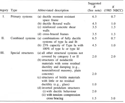
TABLE 2. Suggested force reduction factors R and corresponding K of 1985 NBCC Suggested
R K
Categoly Type Abbreviated description (See note) (1985 NBCC) I. Primary systems (a) ductile moment resistant
space frame
(b) ductile flexural walls (c) reinforced concrete shear
walls
(d) cross-braced frames
11. Combined systems (a) combinations of fully ductile systems of type Ia and Ib (b) 25% capacity of Type la with
100% of type Ic or type Id 111. Special structures (a) all other structural systems not
covered by category I or I1 (b) structures of nonductile
materials with some residual ductility and damping (e.g., nonreinforced masonry, plain concrete)
(c) structures of brittle materials with little or no residual ductility (e.g., glass) (d) inverted pendulum structures
(i) with ductile behaviour (ii) with tension-compression
cross bracing
NOTE: Assuming load factor a~ = 1.0 and S = 1.5/T'I2 G 3.0.
(c) Class$ication of structures: It is suggested that buildings can be classified into three categories: (1) primary systems, (2) combined systems, and (3) special structures. Subdivision of each category would then consist of the description of the various structure types and the corresponding value of K for the 1985 NBCC and the suggested R. This is indicated in Table 2. The calculated values of R in Table 1 have been rounded to the nearest 0.5 value.
Under combined systems, the principle of load sharing with a ductile secondary element of 25% nominal capacity is given favourable rating by decreasing K (or increasing R) by one level as compared with the bare primary element structure. Coupled shear walls with ductile connecting beams could also be included in category 2a along with other combined ductile types of construction.
Special structures would include those not included above and constitute mainly those types that are considered nonearth- quake resistant or those that have fared poorly in previous earthquakes; this includes unreinforced masonry or other struc- tural forms with low ductility, nonredundant systems, or the elevated cross-braced water tower.
8. Summary and conclusions
Some basic considerations that underlie the structural seis- mic design requirements of the 1985 NBCC have been exam- ined. These include load classification of seismic action, load factors, limit states to be considered, classification of structural systems, and correspondence of K-factors with derived force reduction factors R. The following conclusions are reached:
ing to the accidental seismic action should be changed to 1.0 from the current value of 1.5. This would introduce a desirable distinction between seismic loads and wind to account for theif significantly different characteristics.
3. The correspondence between K-factors and a force reduc- tion factor R has been demonstrated, where the latter refers to a constant in the denominator of the base shear formula and indicates the force reduction relative to the expected elastic response of the structure.
4. A new classification of structures and corresponding K- factors and R-factors has been presented. Structures can be grouped into primary systems, combined systems, and special structures that include those with little or no ductility.
5. When a load factor of 1.0 is used for earthquake design loads, the derived values of force reduction factor R corre- spond well with the response modification factors proposed by the Applied Technology Council (ATC-3 1978).
6. The above results can provide a basis for possible future changes of the NBCC seismic provisions.
Acknowledgement
This presentation is based in part on discussion papers that the author presented to the Canadian National Committee on Earthquake Engineering (CANCEE). The writer wishes to acknowledge the stimulating discussions with members of CANCEE and D.E. Allen. The opinions expressed are those of the author and do not neccessarily reflect those of CANCEE or the Associate Committee on the National Building Code.
-
1. Seismic actions should be treated as accidental actions A ~D. E. ~ 1982. ~~ ~istates ,~ design. i ~CBD 221, ~ i ~of i ~ i ~ ~ rather than as variable actions as is currently done in the 1985 Building Research, National Research Council of Canada, Ottawa,
NBCC. Ont
.
454 CAN. J. CIV. ENG. VOL. 14, 1987
regulations for buildings. National Bureau of Standards, Special Publication 510, Applied Technology Council, Washington, DC. CSA. 1981. Guidelines for the development of limit states design. CSA Special Publication S408-1981, Canadian Standards Associa- tion, Rexdale, Ont.
FERAHIAN, R. H. 1971. Comparison of probabilities of wind and earthquake loads in the NBC 1970. Building Research Note No. 72, Division of Building Research, National Research Council of Canada, Ottawa, Ont.
HEIDEBRECHT, A. C., and Tso, W. K. 1985. Seismic loading provision changes in National Building Code of Canada 1985. Canadian Journal of Civil Engineering, 12: 653-660.
HEIDEBRECHT, A. C., BASHAM, P. W., RAINER, J. H., and BERRY,
M. J. 1983. Engineering applications of new probabilistic seismic ground-motion maps of Canada. Canadain Journal of Civil Engi- neering, 10: 670-680.
I S 0 1984. General principles on reliability for structures. I S 0 2394.1986, International Standards Organization, Geneva, Switzerland.
ISHAYAMA, Y. 1985. Comparison of NBC (1985) seismic provisions with Japanese seismic regulations (1981). DBR Paper No. 1297, Division of Building Research, National Research Council of Canada, Ottawa, Ont.
NBCC. 1985a. National Building Code of Canada. Associate Com- mittee on the National Building Code, National Research Council of Canada, Ottawa, Ont.
1985b. Supplement to the National Building Code of Can- ada. Associate Committee on the National Building Code, National Research Council of Canada, Ottawa, Ont.
NEWMARK, N. M. 1970. Current trends in the seismic analysis and design of high-rise structures. In Earthquake engineering. Edited by R. L. Wiegel. Prentice-Hall Inc., Englewood Cliffs, NJ, pp.
1
403-424.NEWMARK, N. M., BLUME, J. A., and KAPUR, K. K. 1973. Seismic design spectra for nuclear power plants. ASCE Journal of the Power Division, 99(P02): 287-303.
PALL, A. S. 1983. Friction devices for aseismic design of buildings. Proceedings, Fourth Canadian Conference on Earthquake Engi- neering, Vancouver, B .C., pp. 475-484.
STIEMER, S. F., and BARWIG, B. B. 1985. Seismic base isolation for steel structures. Canadian Journal of Civil Engineering, 12: 73-81. SEAOC. 1980. Recommended lateral force requirements and com-
mentary. Seismology Committee, Structural Engineers Association of California, San Francisco, CA.
TARICS, A., WAY, D., and KELLY, J. M. 1984. Rubber pads protect building from seismic shock. Civil Engineering, ASCE, August, p.
12.
UBC. 1985. Uniform Building Code. International Conference of Building Officials, Whittier, CA.
UZUMERI, S. M., OTANI, S., and COLLINS, M. P. 1978. An overview of Canadian code requirements for earthquake resistant concrete buildings. Canadian Journal of Civil Engineering, 5: 427-441.
![FIG. 2. Seismic response factor S for the 1985 NBCC. [5] R = 6.8lK seismic ground motions](https://thumb-eu.123doks.com/thumbv2/123doknet/14282759.491800/6.875.41.380.375.621/fig-seismic-response-factor-nbcc-seismic-ground-motions.webp)