READ THESE TERMS AND CONDITIONS CAREFULLY BEFORE USING THIS WEBSITE.
https://nrc-publications.canada.ca/eng/copyright
Vous avez des questions? Nous pouvons vous aider. Pour communiquer directement avec un auteur, consultez la
première page de la revue dans laquelle son article a été publié afin de trouver ses coordonnées. Si vous n’arrivez pas à les repérer, communiquez avec nous à [email protected].
Questions? Contact the NRC Publications Archive team at
[email protected]. If you wish to email the authors directly, please see the first page of the publication for their contact information.
NRC Publications Archive
Archives des publications du CNRC
This publication could be one of several versions: author’s original, accepted manuscript or the publisher’s version. / La version de cette publication peut être l’une des suivantes : la version prépublication de l’auteur, la version acceptée du manuscrit ou la version de l’éditeur.
Access and use of this website and the material on it are subject to the Terms and Conditions set forth at
Gloucester Street watermain rehabilitation - research aspect
Zhao, J. Q.; Daigle, L.; Desnoyers, R.
https://publications-cnrc.canada.ca/fra/droits
L’accès à ce site Web et l’utilisation de son contenu sont assujettis aux conditions présentées dans le site LISEZ CES CONDITIONS ATTENTIVEMENT AVANT D’UTILISER CE SITE WEB.
NRC Publications Record / Notice d'Archives des publications de CNRC:
https://nrc-publications.canada.ca/eng/view/object/?id=62d7937b-3a0e-4122-848a-7d869481e29b https://publications-cnrc.canada.ca/fra/voir/objet/?id=62d7937b-3a0e-4122-848a-7d869481e29b
Gloucester Street watermain rehabilitation
-research aspect
Zhao, J. Q. ; Daigle, L. ; Desnoyers, R.
A version of this paper is published in / Une version de ce document se trouve dans : Infra 99 International Conference, Montreal, Nov. 22-24, 1999, pp. 1-21
www.nrc.ca/irc/ircpubs
GLOUCESTER STREET WATERMAIN REHABILITATION – RESEARCH ASPECT
J.Q. Zhao, Ph.D., P.Eng. L. Daigle, P.Eng. R. Desnoyers
Research Officer Technical Officer Technical Officer
Institute for Research in Construction National Research Council Canada
November 24, 1999
Infra 99 International Convention November 22 to 24 1999 Palais des Congrès de Montréal
ABSTRACT
The Region of Ottawa-Carleton chose the trenchless sliplining method to renovate its 915-mm (36”) diameter cast iron watermain under Gloucester Street, one of the busiest streets in downtown Ottawa. This paper describes the research aspect of this project, which comprises a performance assessment and implementation of
performance monitoring instrumentation in the field.
The performance assessment was carried out to obtain stresses under different loading and thermal conditions and service life expectancy. Both grouted and ungrouted options were evaluated and compared. Laboratory testing of specimens taken from an old cast iron pipe, a high density polyethylene (HDPE) pipe segment and grouted sliplined pipe sections were conducted. The assessment showed that a grouted pipe should perform better. The second part describes the methods for the field installation of sensors on the two pipe materials and the challenges of protecting the sensors during insertion process and completing the installation within the
constraints and schedule of the contract work. A layout of the complete instrumentation, datalogging and communication system is presented.
INTRODUCTION
Sliplining is one of several trenchless techniques used for the rehabilitation of buried municipal pipelines. The method involves pulling (or pushing) a new pipe into an existing host pipe that is in need of rehabilitation due to its degraded hydraulic or structural performance. The annular space between the new and host pipe can be either grouted or left ungrouted. Although it costs less and is easier for construction, the ungrouted option results in higher stress levels in the new pipe wall when the host pipe is still structurally sound. The fact that the existing host pipe is to be rehabilitated does not usually mean it will fail in the immediate future. In many cases it continues to be structurally sound for many years to come, which will provide additional time span to the service life of the new pipe. The probability of collapse of the host pipe is reduced after the rehabilitation because the stress levels in its pipe wall are reduced. The Region of Ottawa-Carleton engaged the Institute for Research in Construction of the National Research Council Canada prior to the contract tender for the
performance assessment of the watermain to be rehabilitated by the trenchless sliplining using HDPE pipe. The cast iron watermain, located under Gloucester Street in downtown Ottawa, was originally constructed between 1916 and 1917. Its
operating pressures range from 275 to 715 kPa, with transient pressures up to 1,035 kPa (Willmets 1998). The 840 mm (33”) O.D. HDPE pipe with a dimension ratio (DR) of 17 was chosen to slipline the 82-year-old cast iron pipe. The pressure rating for DR 17 HDPE pipe is 714 kPa.
Although the sliplining technology has been applied in Europe and the United States, there is little field data available, especially for climatic areas like the Ottawa-Carleton region. To obtain the much-needed field data on long-term performance, a
performance monitoring system installed during the field rehabilitation of the Gloucester Street watermain. The details of the instrumentation and challenges of installing and protecting the sensors are also summarised in this paper.
PERFORMANCE ASSESSMENT OF HDPE SLIPLINING
The performance assessment of the sliplined watermain was carried out in two phases - Phase I: preliminary performance assessment of HDPE sliplining, grouted vs. ungrouted; Phase II: detailed performance assessment. The assessment of stress levels in pipe walls can help understand the effect of various factors such as modulus ratio, diameter ratio and thickness ratio. The service life of the rehabilitated pipe is discussed in relation to stress levels.
In Phase I, a preliminary assessment was carried out in terms of circumferential stress under internal and external loading, thermal stress, shear stress, buckling under internal vacuum and external loading, and service life expectancy. Both grouted and ungrouted sliplining options were evaluated and compared. The
assessment showed that a grouted pipe was expected to perform better with a longer service life (Zhao 1998).
In Phase II, a detailed performance assessment of the grouted sliplining option was carried out. As part of the assessment, laboratory tests were conducted on
specimens taken from an old cast iron pipe, two HDPE pipe segments and grouted sliplined pipe sections. The tests included mechanical, ring bending, thermal
expansion/contraction, and friction coefficient measurements. Mechanical Testing
Tensile, flexural and compression strengths of HDPE specimens were tested using specimens prepared from an HDPE pipe made with PE 3408 resin. The test results are summarized in Table1. The mean tensile yield strength, based on four tests, of 23.9 MPa is almost identical to the typical value given by PPI (1993) and the mean flexural yield strength, based on two tests, of 24.2 MPa is almost identical to the typical value given in ASTM D 638-96. The modulus of elasticity values determined in the tensile and compression tests, are close to the lower limit of the given range, and that determined from the bending tests close to the upper limit. ASTM D 790-96a mentions that the modulus determined from bending tests may not correlate with the modulus determined from tensile testing. The test results confirmed the short-term mechanical properties of PE 3408 polyethylene pipe material.
Table 1. Tested short-term strengths of HDPE specimens.
Property Mean tested
value, MPa
Value in reference, MPa
Reference source
Tensile yield strength 23.9 24.3 ASTM D 638-96
Flexural yield strength 24.2 24.3 ASTM D 638-96
Compression strength not reached N/A
Modulus of Elasticity by tensile test 370 380 to 700 Driscopipe 1996a; PPI 1993 Modulus of Elasticity by compression test 301 380 to 700 Driscopipe 1996a; PPI 1993 Modulus of Elasticity by flexural test 830 380 to 700 Driscopipe 1996a; PPI 1993 Laboratory Ring Bending Test
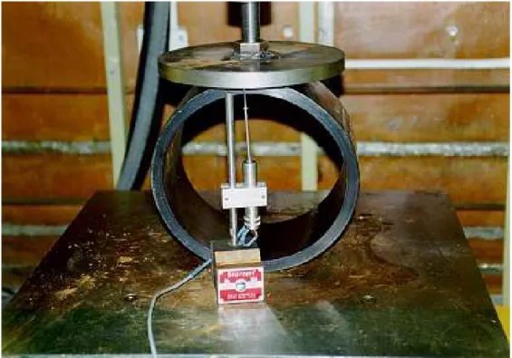
Ring bending tests were performed with ring specimens prepared from the cast iron pipe, HDPE pipe, composite cast iron-grout pipe (two materials) and composite cast iron-grout-HDPE pipe (three pipe materials) (Figures 1 to 4).
Figure 2. Testing of a cast iron pipe ring.
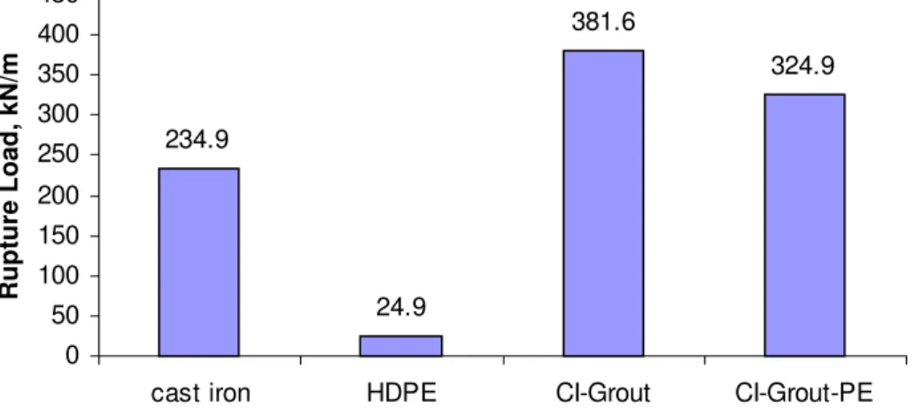
Figure 4. Testing of a cast iron-grout-HDPE pipe ring (three materials). Figure 5 shows the rupture loads for the four types of ring specimens tested. The average rupture load of the cast iron rings, based on four tests, is 234.9 kPa, whereas the average collapse load (termed “rupture load” in Figure 5) of the HDPE rings, based on three tests, is 24.9 kPa. The tests of 11 cast iron-grout-HDPE rings yielded an average rupture load (cast iron ruptured) of 324.9 kPa. The tests of four cast iron-grout rings (with HDPE rings removed) gave an average of 381.6 kPa. The load carrying capacity of the cast iron-grout pipe and the cast iron-grout-HDPE pipe were 62.5% and 37.7% higher than the cast iron pipe alone. Theoretically, the resistance of the three material composite pipe should be higher than the two material composite. The cast iron-grout-HDPE pipe specimens were tested at 8, 42 and 51 days after grouting, whereas the cast iron-grout pipe specimens were tested at 84 days. The additional curing time of 33 days may have increased the strength of the grout ring, resulting in a 17% increase in load carrying capacity.
Figure 6 summarises the pipe stiffness based on the rupture loads and measured vertical deflections. The results show clearly that the grout played an important role in improving the structural capacity of the grouted pipe. A similar increase in load carrying capacity was reported by Osako et al (1998). In their study, a box culvert was lined with a spiral wound liner and the cavity was grouted.
Figure 5. Comparison of pipe rupture loads.
Figure 6. Comparison of pipe stiffness factors.
The modulus of elasticity of the HDPE pipe, calculated based on the ring bending tests, is 653.1 MPa, which is close to the upper limit of the 380 – 700 MPa range given by Driscopipe (1996a).
The thickness of the grout ring was not uniform due to offset of the HDPE pipe from the axis of the cast iron pipe. Ring bending tests were conducted with different
orientations of the thinnest grout point to determine its effect on the ring performance. The tests showed that all the composite ring specimens failed with cracking either near the crown or the invert regardless of the direction and magnitude of offsetting. This offset did not seem to affect the rupture load, either.
8.9 0.2 13.6 14.5 0 2 4 6 8 10 12 14 16
cast iron HDPE CI-Grout CI-Grout-PE
Pipe stiffness factor, MPa
234.9 24.9 381.6 324.9 0 50 100 150 200 250 300 350 400 450
cast iron HDPE CI-Grout CI-Grout-PE
Rupt ure Loa d, k N /m
The load carrying capacity so determined is directly proportional to that of a buried field pipe. The pipe field strength relates to the (2-point or 3-point) bearing test strength by a bedding factor, which depends on the type of bedding and material. Support from the bedding and backfill materials improves the load carrying capacity of the pipe. For this assessment, the load carrying capability refers to that determined using the two-point loading method.
Load Sharing
The HDPE, grout and cast iron pipe in a grouted sliplined pipe act together to resist portions of internal and external loads. Two unique features of the pipe system are: 1. A portion of the internal load is required to expand the HDPE pipe to close a small
annular gap caused by the differential thermal contraction due to seasonal
temperature variations (∆T = 20ºC) and grout shrinkage. Only the remainder of the internal loading is distributed to the three pipe rings according to their relative hoop stiffness as:
where Hoop Stiffness (HS) is defined:
Ei – Modulus of elasticity of material i (i = PE, CI and GR, representing HDPE,
cast iron and grout, respectively),
ti – thickness of the pipe ring,
Di – mean pipe ring diameter.
RPE, RCI, RGR - portions of the internal load taken by the HDPE, cast iron and
grout pipe ring, respectively.
2. The trenchless sliplining technique allows HDPE insertion and annular grouting while the host pipe is under continuous external soil loading. As a result, the host
i i i i D t E HS = CI GR PE GR GR HS HS HS HS F R + + = ' CI GR PE PE PE HS HS HS HS F R + + = ' CI GR PE CI CI HS HS HS HS F R + + = '
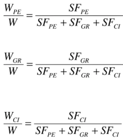
cast iron pipe takes the full external soil load before, during and after the construction. The three pipe materials in the grouted pipe share only additional surface loads transferred through the soil. Neglecting the bond strength at the interfaces, these additional loads are distributed according to their relative pipe stiffness factors as:
where pipe stiffness factor (SF) is defined as (Howard 1981):
WPE, WCI and WGR - portions of external load carried by the HDPE, cast iron
and grout ring, respectively
W - total external load Ii - moment of inertia.
Stress Levels and Service Life
Mechanical properties of HDPE pipe depend on many factors such as temperature, stress levels, rate and duration of loading and the process used to manufacture the pipe. Its service life is known to depend on stress levels and temperature (PPI 1993, 1997, 1998; ASTM D2837-92; Driscopipe 1996a). Charts are available for
determining service life based on temperature and stress levels (Driscopipe 1996a). In general, the lower the stress levels, the longer the service life.
Table 2 shows the stress levels in the HDPE pipe for the load combinations
considered. Based on an allowable strength of 11,030 kPa for DR 17 HDPE pipe, the factor of safety is:
Factor of safety CI GR PE PE PE SF SF SF SF W W + + = CI GR PE GR GR SF SF SF SF W W + + = CI GR PE CI CI SF SF SF SF W W + + = 3 i i i i r I E SF = 7 = = 1,600 11,030
This factor of safety is in addition to the factor of safety of 2 incorporated into the allowable strength (Driscopipe 1996b; Sclairpipe 1996b).
Table 2. Circumferential stresses in HDPE pipe
Load combination
Maximum circumferential stresses (kPa) 1: internal operating pressure + external earth load +
external surface traffic load + thermal load
1,590 2: internal operating pressure + internal surge pressure +
external earth load + thermal load
1,600
3: internal transient vacuum pressure + external earth load -810
4: external earth load + external surface traffic load 40
The service life of HDPE pipe is projected to be more than 50 years for a stress level of 5,516 kPa (800 psi) (Driscopipe 1996a). Based on a maximum stress level of less than 1,600 kPa (232 psi), the HDPE pipe will be stressed only to 7% of its yield strength as long as the host cast iron retains its structural capacity. The inserted HDPE pipe will act as a watertight liner until the host pipe fails.
Furthermore, the laboratory tests show that a grouted old cast iron pipe can withstand higher external loads. Hoop tensile stresses in the host cast iron make up 16%, 0% and 5% of the total stresses for the original, ungrouted and grouted pipe, respectively. The results show that external loading has a greater impact on the stress levels of the cast iron pipe than internal loading. The flexural stress in the grouted pipe is 15% less than that in the original pipe. Lower stress levels in the host cast iron pipe mean that the cast iron pipe lasts longer, or provides longer protection to the inserted HDPE pipe. As a result, the service life of the watermain will be much extended.
Some literature indicates that voids may be created in thick-walled HDPE pipe as a result of the manufacturing process (Barker et al 1983; Bjorklund and Janson 1981). These flaws can become crack initiation locations under high cyclic stresses.
Scratches on the exterior surface of the HDPE pipe caused by protruding points on the interior surface of the host pipe during installation can also become potential crack initiation locations. When a critical strain limit of 6% to 7% is reached, crack propagation in the HDPE pipe is accelerated (PPI 1993). Thus, low stress/strain levels in the HDPE pipe wall reduce the potential for crack development and propagation.
FIELD INSTRUMENTATION
Sensors were installed on the east and west sides of the Gloucester Street/Bay Street intersection. This location was one of two locations considered because of the presence of a valve chamber where the datalogging equipment could be installed. The other location also had a valve chamber but was rejected because of the higher flow of traffic that might be hindered during the course of the sensor installation. The sensors installed include strain gauges on both the host and liner pipes,
thermocouples on the pipe surface and in the soil backfills, a pressure transducer on the watermain and two-time domain reflectometry probes for in-situ moisture content measurements.
Strain Gages
Strain gages are used to measure the deformation on the cast iron host pipe and on the HDPE liner. Monitoring of the gages will continue for a three to five-year period depending on the life span of the sensors. Of all the sensors installed for this project, strain gages are the most delicate and their performance and life expectancy depend strongly of the quality of the installation.
Prior to the installation of strain gages on cast iron and HDPE pipes, many trial installations were carried out in the laboratory to select the most suitable methods of bonding and coating on both materials. The strain gages themselves were selected to account for different mechanical and thermal properties of the two materials. The ease and time required for the installation as well as the magnitude of expected loading during the lining process and in service were also important factors considered in their selection. Other critical factors considered for the installation include:
• surface preparation requirement,
• minimized interference with contractor’s work, and
• protection of the pre-installed gages and cables during the insertion process. Two lengths of HDPE liner, measuring 3 m each, were sent to NRC’s laboratories for installation of the strain gages. The process included the preparation of the HDPE surface to allow a proper bonding of the gages, the bonding and the application of a protective coating against humidity and to minimise friction on the gage and lead attachments during the liner insertion. Surface preparation is crucial. Scratches and irregularities were removed by abrasive paper. The surface was oxidised and
neutralised to improve the bondability. Two-element 90° rosette gages were bonded with a special epoxy following the manufacturer’s recommended procedure. The gages had a nominal resistance of 1000 ohms (instead of the widely-used 350 ohm gage) to reduce the heating effect created by the voltage supplied while reading the
gage and the poor thermal conductivity of the plastic. The protective coating consisted of a 150 mm x 150 mm piece of fiberglass impregnated with epoxy,
covering the entire strain gage assembly area. A general-use epoxy was applied over the fiberglass and around the cable entry to make the fiberglass less permeable and more resistant to abrasion during insertion.
A total of sixteen strain gages were installed on each pipe length as shown in
Figure 7. The dual gauge sensors were positioned at 12, 3, 6 and 9 o’clock positions around the pipe circumference. This circular array was repeated two times at an interval of 0.5 m on both lengths of pipe (Fig. 8). Thermocouples were installed close to the strain gages on the HDPE pipe at the 12, 6 and 9 o’clock positions. Each cable was then bundled and strapped to the pipe for delivery to the site. The HDPE pipe sections with attached sensors were handled with great care to prevent damage during transportation and delivery.
The installation of strain gages on the cast iron pipe was carried out on site. The challenge was to find a quick and suitable technique that could be used by persons in the confined space of a 915-mm diameter pipe. Weldable strain gages were chosen for their ease of installation and for the minimal surface preparation. The strain gages used were T-rosette biaxial gages with pre-attached lead wires.
Sensors were installed at 6.5 m and 7.3 m from the access hole. The soil on top of the strain gage locations was maintained undisturbed for at least 2 m around to ensure monitoring of a trenchless installation.
EAST SECTION - HDPE
NORTH SIDE NORTH SIDE SOUTH SIDE SOUTH SIDE 9 1 0 11 12 13 14 1 5 16 2 5 26 27 28 29 30 31 32 4 2 STRAIN GAGE STRAIN GAGE NUMBER 33 34 35 36 3 7 38 39 40 3 4 5 6 7 8 SECTION 1 SECTION 2 SECTION 2 SECTION 1
BAD STRAIN GAGE
THERMOCOUPLE
WEST SECTION - HDPE
1 2
Grouting Chimney E1 TC array E2 TC array E3 TC array
EAST SIDE OF VALVE CHAMBER
CI SG
HDPE SG
CI SG
HDPE SG
WEST SIDE OF VALVE CHAMBER
W1 TC array Valve Chamber 2.1 m 0.6 m 7.7 m 5.0 m 7.3 m 0.4 m 0.5 m 1.6 m 6.0 m 7.0 m 0.5 m 0.35 m
Cast Iron Pipe HDPE Pipe CPP
Cast Iron Pipe HDPE Pipe CPP SG : STRAIN GAGE TC : THERMOCOUPLE CPP: CONCRETE PRESSURE PIPE
Figure 8. Site layout of thermocouple and strain gage locations.
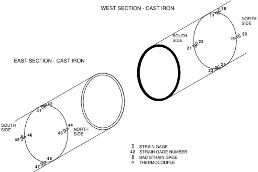
To install the strain gages, large surface areas needed to be prepared in order to find a suitable location free of graphite. A smooth finish was given using abrasive paper. Strain gages were then spot-welded in place at 12, 3, 6 and 9 o’clock positions. Figure 9 illustrates the arrangement of the strain gages and thermocouples on the cast iron pipe. Cables were housed inside 1½" PVC conduits cut in half and fastened to the inner pipe wall using copper straps. Finally, gage areas were protected with a layer of fiberglass covered with epoxy (Fig. 10).
HDPE Pipe Insertion
A 50 m length of HDPE liner, including the NRC instrumented section, was pushed in at the Bay Street insertion pit in a westward direction. The end of the liner section was already fitted out with a metal flange followed by a fused HDPE flange. All sensor cables were taped flat along the pipe wall.
WEST SECTION - CAST IRON
EAST SECTION - CAST IRON
NORTH SIDE NORTH SIDE SOUTH SIDE SOUTH SIDE 1 7 1 8 1 9 2 0 2 1 2 2 2 3 2 4 4 1 4 2 4 3 4 4 4 5 4 6 4 7 4 8 4 2 STRAIN GAGE STRAIN GAGE NUMBER BAD STRAIN GAGE THERMOCOUPLE
Figure 9. Strain gage locations on cast iron host pipe.
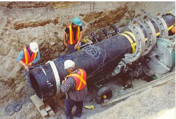
A first attempt was made to insert the liner, but the presence of too many utilities crossings over the insertion pit made it impossible to bend the liner pipe enough for insertion. A longer pit was then dug and the insertion process resumed (Fig. 11). Four bearings were installed at the entry of the host pipe to centre the liner during the insertion and to avoid damaging the cables installed inside the cast iron pipe.
As the sensors were entering of the host pipe, no significant rotation of the strain gage location was observed. The final position of the liner was adjusted over the following days when final connections were made at the western end. The
instrumented sections on the HDPE and cast iron pipe lie within 500 mm of each other.
The insertion of the east section liner proceeded differently from the west side. A standard liner length (non-instrumented) was pushed inside the cast iron pipe from an eastern pit located at the intersection of Gloucester and Lyon Streets. To fuse the instrumented section, the liner was pushed past the cast iron pipe end into the pit. Then, the fusing machine was lowered into the pit where the fusion of the
instrumented section to the already inserted piece of liner took place. After the instrumented section was attached, the liner was pulled back so that the sensors would reach their desired final positions (Fig. 12).
Resin coated Fiberglass
Figure 10. Strain gage sensors and cable protection.
Figure 12. Insertion of east section of instrumented HDPE pipe. During the insertion process, six cables snapped and were immediately repaired. After the insertion was completed, all cables and sensors were checked and repaired where possible. Of the 48 strain gages installed on both cast iron and HDPE pipes, 8 are apparently not responding.
Thermocouple, TDRs and Pressure Transducer
Type T thermocouples having a precision of 71.0 °C and a working range of –60 °C to 100 °C were used. Prior to field installation, all thermocouples were calibrated in a temperature-controlled environmental chamber. Single pair cables were used for installation on the cast iron pipe and HDPE pipe close to the strain gage locations. Twelve pair cables were cut and soldered in the laboratory and mounted on wood stakes as vertical thermocouple arrays in the field.
Soil temperatures at different depths are measured at four different locations. The vertical thermocouple arrays extend from the top of the pipeline to the bottom of the asphalt layer. The location of each array is shown in Figure 8.
Time domain reflectometry (TDR) probe measures the volumetric water content in the soil. Two TDR probes were installed into the soil backfill from the trench walls near the eastern instrumentation section. The deeper one is located at the same elevation as the top of the cast iron pipe or approximately 1480 mm from the pavement
surface. The shallower one is installed horizontally from the trench side wall at a depth of approximately 800 mm from the pavement surface.
The watermain pressure is measured with a pressure transducer ranging from 0 to 1380 kPa (200 psi) with an overload capacity of 2760 kPa (400 psi). The sensor was installed by the contractor in a nipple off the pipeline inside the valve chamber. The performance of the pressure transducer was verified at the NRC Laboratories. Datalogging Equipment
Two dataloggers/controllers are used to take readings from all the sensors. They are fully programmable, battery powered and tested to operate at temperatures ranging from –40 °C to 50 °C. A CR10 datalogger along with three 16-channel multiplexers are used to control and take measurement readings from all the strain gages, the TDR probes and the pressure transducer every hour. The 63 thermocouples installed for this project are connected to a CR7 datalogger for hourly measurements of the ground and pipe temperatures.
For each datalogger, the data is stored in its internal memory and in a storage back-up module. Each datalogger is also connected to its own modem and then to a common line-sharing device which allows the use of a single telephone line. The three 16-channel multiplexers are housed in a separate environmental enclosure but are linked and controlled by the CR10. Communication with the dataloggers can be established directly through a computer RS-232 link to download the program,
monitor sensor measurements, transfer stored data to a computer file and many other tasks. Remote communication is established through telephone link directly from NRC Laboratories to download the collected data (Figure 13).
SUMMARY AND CONCLUSIONS
A detailed performance assessment was conducted of the proposed sliplined watermain under Gloucester Street in Ottawa, prior to the construction tender. The evaluation included laboratory testing on tensile, bending and compression properties of HDPE pipe using test specimens prepared from a 510 mm diameter DR 26 HDPE pipe. Ring bending tests were also conducted on pipe specimens prepared from an HDPE pipe, a cast iron pipe and a composite pipe made of these two pipes by grouted sliplining.
Theoretical formulas were derived and verified using the test results. These formulas were then used to determine the stress levels in the proposed rehabilitated 915-mm diameter watermain. The performance assessment was made based on
CR7 - Datalogger Mpx. 1 1000 Ohms Mpx. 2 1000 Ohms Mpx. 3 350 Ohms 12 V Batt. 12 V
Batt. Storage module -CR10 Storage module -CR7 CR10 - Datalogger Multiplexers CR10 Modem CR7 Modem Line sharing device
TELEPHONE JACK ELECTRICAL JACKS TRANSFORMERS Strain gages Strain gages Strain gages TDR - Pressure sensor Thermocouples CR10 Datalogger, communication and back -up systems
16" x 18" Fiberglass environmental enclosure On site
On site
NRC
Figure 13. Dataloggers and communication set-up. Performance Assessment
The following conclusions can be drawn based on the laboratory testing and performance assessment:
• Mechanical testing has confirmed the properties of PE 3408 HDPE pipe as reported in the literature.
• Grouting the annulus with a cement-based grout can improve the structural capability of the rehabilitated pipe. Rupture load was increased by approximately 38% in the grouted test rings compared to the cast iron test rings only. Grouting in conjunction with a liner pipe can be considered as an effective method for
strengthening deteriorated pipe sections in underground pipeline.
• Internal loading is distributed to the three pipe materials in a grouted sliplined pipe according to their relative hoop stiffness, whereas external loading is distributed according to their relative pipe stiffness.
• The maximum circumferential stress in a grouted HDPE pipe is only about 15% of the allowable strength in the worst load combination. This means that the HDPE pipe acts essentially as a watertight liner while the strength of the existing cast iron pipe is fully utilized.
• The stress level in the grouted cast iron pipe is about 15% lower than that of the original pipe. This reduction in stress means longer remaining service life for the existing host pipe.
• Based on the stress level in the HDPE pipe and the fact that the grouting strengthens the host cast iron, the renovated pipe will have a service life well beyond 50 years.
Field Performance Monitoring
A field instrumentation system has been successfully installed to monitor the performance of the HDPE sliplined cast iron watermain in Ottawa. This monitoring system contains dual strain gauges on the host cast iron pipe and on the liner HDPE pipe at two separate sections. Thermocouples were also installed on the pipes and in the backfill soils above the instrumented pipe sections. Two TDR probes were
installed in the backfill soils to measure the in situ moisture contents. A pressure transducer was also installed to measure the hydrostatic pressure inside the
watermain. Remote communication with the monitoring system is done via a modem and telephone line.
The challenges included installing strain gages onto HDPE pipe in the laboratory and onto the rusty cast iron pipe in the field. Insertion of the HDPE liner pipe with sensors and cables attached required the collaborative effort of the research team, the Region of Ottawa-Carleton inspectors and the contractor. The installation was accomplished within the constraints and schedule of the contract work.
ACKNOWLEDGEMENTS
Funding for this research was jointly provided by the Region of Ottawa-Carleton and the National Research Council Canada. Assistance from Messrs. Michael Willmets, Michel Robitaille and Derel Upton of the Region of Ottawa-Carleton and Mr. Derek Potvin of Robinson Consultants during the course of the project is gratefully
acknowledged. The collaboration of Mr. Bill McShane and the on-site employees of Dufferin Construction is gratefully acknowledged. Comments from Dr. Balvant B. Rajani for the preparation of this paper are greatly appreciated.
REFERENCES
ASTM D 638-96. 1996. Standard Test Method for Tensile Properties of Plastics. American Society for Testing and Materials.
ASTM D 790-96a. 1997. Standard Test Methods for Flexural Properties of
Unreinforced and Reinforced Plastics and Electrical Insulating Materials. American Society for Testing and Materials.
ASTM D 2837-92. 1992. Standard Test Method for Obtaining Hydrostatic Design Basis for Thermoplastic Pipe Materials. American Society for Testing and Materials.
Barker, M.B. and Bevis, J.B. 1983. The performance and causes of failure of
polyethylene pipes subjected to constant and fluctuating internal pressure loadings. Journal of Materials Science, 18:1095-1118.
Bjorklund, I., Janson, L.E. 1981. Swedish Experience of the Use of Thermoplastic Pipes for Water and Sewer Transport. Proc. of the International Conference on Underground Plastic Pipe, ASCE, pp. 385-399.
Driscopipe. 1996a. Engineering Characteristics. Phillips Driscopipe. Driscopipe. 1996b. Systems Design. Phillips Driscopipe.
Howard, A.K. 1981.The USBR equation for predicting flexible pipe deflection. Proc. Int's Conf. on Underground Plastic Pipe, B.J.Schrock (ed.) ASCE, pp.37-55
Osako, K., Takahashi, Y., Kitahaasi, N., Akimoto, E., Nakatsui, K. and Nakano, M. 1998. Renovation technology and evaluation of load carrying capacity for sewage pipe renewal method. a paper submitted to Conference on Infrastructure
Regeneration and Rehabilitation, Improving the Quality of Life Through Better Construction, A Vision for the Next Millennium, UK, June 28 – July 2, 1999. Potvin, Derek. 1998. Private communication. Robinson Consultants, Ottawa.
PPI. 1973. Weatherability of Thermoplastic Piping, Technical Report TR-18/73, The Plastics Pipe Institute.
PPI. 1993. Engineering Properties of Polyethylene. The Plastics Pipe Institute. PPI. 1997. Hydrostatic Design Bases and Maximum Recommended Hydrostatic Design Stresses for Thermoplastic Piping Materials, TR-4/97b. The Plastics Pipe Institute.
PPI. 1998. HDB Policies, TR-3. The Plastics Pipe Institute.
Robinson. 1998. Gloucester Street Watermain Rehabilitation. Prepared for the Municipality of Ottawa-Carleton, Robinson Consultants Inc.
Sclairpipe. 1996b. High Density Polyethylene Pipe Systems Design. KWH Pipe. Willmets, Michael. 1998. Private communication. Region of Ottawa-Carleton. Zhao, J.Q. 1998. Preliminary Performance Assessment of HDPE Relining of Gloucester Street Watermain. Client Report B-5105.1. Institute for Research in Construction, National Research Council of Canada.