OF MODEL COMPOUNDS IN A TRICKLE BED REACTOR
by
SHAN HSI YANG
S.B., National Tsing Hwa University (1972)
Ph.D., Brandeis University (1976)
SUBMITTED IN PARTIAL FULFILLMENT OF THE REQUIREMENTS FOR THE DEGREE OF
DOCTOR OF SCIENCE at the
MASSACHUSETTS INSTITUTE OF TECHNOLOGY October, 1982
©
Massachusetts Institute of Technology 1982l. , ./
Signature of Author
Department of Chkmic6 Engineering October 7, 1982 Certified by Charles N. Satterfield Thesis Supervisor Accepted by
Archve
MASSACHUSETTS INSTITL OF TECHNOLOGY DEC 3 1982 Glenn C. Williams Chairman, Departmental CommitteeITE on Graduate Students
LIBRARIES
OF MODEL COMPOUNDS IN A TRICKLE BED REACTOR
by
SHAN HSI YANG
Submitted to the Department of Chemical Engineering on October 7, 1982 in partial fulfillment of the requirements for the Degree of Doctor of Science.
ABSTRACT
The hydrodenitrogenation reaction network of quinoline was studied over a sulfided NiMo/A1203 catalyst at temperatures of
350°, 3750 and 3900C and a pressure of 6.9 MPa, using
quinoline or various intermediate reaction products in the presence of an inert paraffin liquid. Equilibrium between quinoline and 1,2,3,4 tetrahydroquinoline is rapidly attained.
The hydrogenolysis of CN bond follows the hydrogenation of heterocyclic or aniline ring. Propylcyclohexane was the
predominant hydrocarbon product, though the ring isomerization of propylcyclohexene was observed.
A Langmuir-Hinshelwood type kinetic model was employed. The reaction rate constants for the various reactions in the network are very similar to those for the same reactions in the vapor phase, although the liquid tends to equalize the adsorptivities of the various N-compounds present. Over a wide range, for a specified pressure and temperature, the
percent conversion as a function of contact time is remarkably similar for iquid and vapor phase processing. In both cases, the overall ;.DN reaction is essentially zero order under the
conditions sudied.
The presence of H2S (generated in situ from CS2) in the
overall reaction network somewhat inhibits hydrogenation and dehydrogenation reactions but markedly accelerates
hydrogenolysis reactions, for a net increase in the overall rate of hydrodenitrogenation. H S has little effect on the activation energies for the hydrogenation and dehydrogenation reactions, but significantly reduces those for the
hydrogenolysis reactions. The presence of H S also significantly increases the ring isomerization of
propylcyclohexene in quinoline HDN. Two kinds of catalytic sites, sulfur anion vacancies and Brosted acid sites, are proposed to explain the effect of H2S on HDN reactions. An H2S molecule under reaction conditions can convert one sulfur vacancy to one Brsted acid site on the surface of sulfided
-1-NiMo/A1203.
The presence of tetralin in the liquid inhibits the overall hydrodenitrogenation reaction, indicating that
inhibition by competitive adsorption is more important than the accelerating hydrogen-donor capability that tetralin exhibits in some homogeneous reactions.
The hydrodeoxygenation (HDO) reaction networks of alkylphenol, benzofuran, and benzylether were separately studied at 375C and 6.9 MPa. The HDO of alkylphenols and benzofuran proceeds via hydrogenation of the heteroring or phenolic ring followed by the rapid formation of water and two
isomers of alkylcyclohexene which then react further.
In selected binary mixtures of a heterocyclic nitrogen compound and phenolic or heterocyclic oxygen compound and in the presence of H2S, the rate of hydrodeoxygenation (HDO) was considerably decreased in comparison to that observed with same compound individually at the same reaction conditions. The rate of hydrodenitrogenation (HDN) of quinoline was
increased and the effect on the HDN rate of o-ethylaniline depended on the specific oxygen compound. Traces of water vapor increase hydrodenitrogenation if H2S is also present.
The results are interpreted in terms of the relative importance of competitive adsorption, water formed by the HDO reaction, alteration of the catalyst structure and possibly hydrogen bonding between species.
The method of presulfiding of a commercial NiMo/A1203 catalyst has a significant effect on its inherent activity for the hydrodenitrogenation of quinoline (HDN). In addition, during reaction the addition of H2S increases the HDN rate and its removal decreases it in a reversible manner. The optimal
sulfiding conditions for hydrodesulfurization (HDS) and HDN are discussed. The effect of H2S on the kinetics of a variety of hydrodenitrogenation, hydrodesulfurization, and
hydrogenation reactions on molybdenum catalysts reported by several researchers are seemingly controversial. Such results can be rationalized in terms of the H2S effect on two kinds of
sites, sulfur anion vcancies and Brested acids proposed in this work.
Thesis Supervisor: Dr. Charles N. Satterfield Title: Professor of Chemical Engineering
Acknowledgement
First and foremost, I wish to thank my thesis advisor, Professor Charles N. Satterfield. I am grateful for the
opportunity to work in catalysis and reaction engineering with him, and am especially indebted to him for his guidance,
stimulation and critical evaluation.
I would like to thank Professor Glen C. Williams for his encouragement and advice.
I wish to express my gratitude to Professors James Wei, William M. Dean, John P. Longwell, Robert C. Armstrong, and Robert C. Reid for their illuminating lectures and valuable discussions. Thanks also go to other professors in the department. The whole department has made my stay at MIT interesting and rewarding.
I wish to thank Al J. Pukt, Jr. and Frank L. Woodword for their help in the course of constructing the experimental
apparatus.
Dr. Cathy E. Costello, Robert A. Bethem, and Kin Chiu of NIH Mass Spectrometry Facility are acknowledged for the ana-lyses of gas chromatography/mass spectrometry. I am espe-cially grateful to kin for his analysis at the very last stage of the thesis work.
I am thankful to Dr. Fred A. Putnam for letting me use his high vacuum system. Dr. Jim A. Simm, Bob Dicosimo, and Jim C. Mitchner were helpful in the phase of IR Adsorption
study which is not reported in this thesis.
Dr. Donald J. Berets at the Stamford Research Center of American Cyanamid is acknowledged for providing the character-ization of HDS-3A catalyst and the alumina support.
I am grateful to many fellow graduate students (some have graduated) for their friendship and valuable discussions. In particular Myongsook Lee, Jim N. Michaels, Chris E. Schwier, Jeff J. Weimer, Chi-Wen Hong, Hisham Ettouney, Cathy E. Teage, Calvin T. Chew, Denise L. Carter, and my labmates Ian A. Webster and Bob A. Ware.
The Department of Energy is acknowledged for supplying the financial support for this work.
Finally I wish to thank my husband Mai for all the love and understanding he has given to me while we were two
TABLE OF CONTENTS:
Page Chapter I: Introduction and Background 19
I.1. Introduction 19
I.2.Processes 22
I.3.Characterization of Heteroatoms in Syncrudes 22 I.4.Reactions on Hydrotreating Catalysts 26
I.4.1.Hydrodesulfurization (HDS) 28 I.4.2.Hydrodenitrogenation (HDN) 30 I.4.3.Hydrodeoxygenation (HDO) 33 I.5.Reaction Kinetics 34 I.6.Catalyst 35 I.6.1.Composition 36 I.6.2.Structure 39
I.6.3.S/Mo Ratio and HDS Activity 40
I.6.4.Catalyst Sites 42
I.7.Trickle Bed Reactor 45
I.7.1.Hydrodynamics 45
I.7.2.Effective Catalyst Wetting 46
I.7.3.Catalyst Dilution in a Laboratory-Scale
Trickle Bed Reactor 47
I.8.Thesis Objectives 49
I.8.1.Design a Laboratory-Scale Trickle Bed
Reactor 49
I.8.2.Quinoline HDN in a Trickle Bed Reactor 51 I.8.3.The Effect of H2 S on Quinoline HDN and
Selectivity of sulfided CoMo/A1203 catalyst 52 I.8.4.Simultaneous HDO and HDN of Model Compounds 52 I.8.5.Catalyst Structure and Catalytic Activity 53
I.8.5.1.Effects of Presulfiding on HDN
Activity 54
I.8.5.2.Effect of H2S on HDN, HDS, and HDO 54
Chapter II: Experimental 57
II.l.Experimental Apparatus 57
II.1.2.Liquid Feed System 60
II.1.3.Trickle Bed Reactor 61
II.1.4.Gas Liquid Separation and Sampling 64
II.1.5.Automatic Safety Design 65
II.1.6.Clean Up System 66
II.2.Experimental Procedure 68
II.2.1.Start Up Trickle Bed Operation 68
II.2.2.Sampling 69
II.2.3.Shutdown Procedures 70
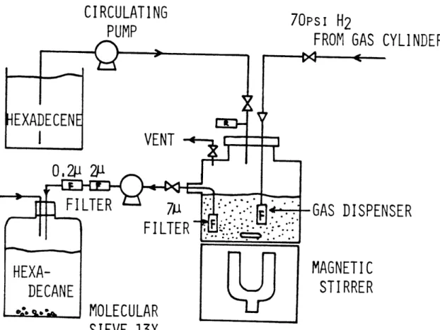
II.3.Liquid Carrier 70
II.3.1.Search for a Suitable Carrier Liquid 70 II.3.2.Hydrogenation of d-Hexadecene 71 II.3.3.Thermocracking of Liquid Carrier 76
II.4.Sample Analysis 78
II.4.1.Gas Chromatographic Condition 78
II.4.2.Product Composition 80
II.4.3.Mass Balances 89
II.5.Catalyst 90
II.6.Gas and Liquid Flow Rates 92
II.6.1.Gas/Liquid Ratio 92
II.6.2.The Choice of Liquid Flow Rates 93
II.6.3.Complete Catalyst Wetting 96
II.7.The effect of Gas Flow Rate on Reaction 96
II.8.Trickle Bed Reactor Design 100
II.8.1.Reactor Performance 100
II.8.2.External Mass Transfer 102
II.8.3.Pore Diffusion Limitations 106
II.8.4.Heat Effects 108
Chapter III: Catalytic Hydrodenitrogenation of
Quinoline 110
III1. Introduction 110
III.2.Catalytic Activity and Reaction Conditions 111
III.2.1.Catalytic Activity 111
III.2.2.Reaction Condition 115
III.3. Results 118
III.3.1.Products Formed in Quinoline HDN 118 III.3.1.1.Saturated Cyclic Hydrocarbons 120 III.3.1.2.2-Propylcyclohexylamine 128
III.3.1.3.Hydrogenolysis of Decahydroquinoline 130 III.3.1.4.HDN of o-Propylaniline 130
III.3.1.5.C-C Bond Cracking 131
III.3.1.6.Side Reactions 132
III.3.1.7.Heavier Products 132
III.3.1.8.Final Products 135
III.3.2.Homogeneous Hydrogen-Donor reaction 135 III.3.3.Homogeneous Reaction of Quinoline 138
III.3.4.Overall Reaction Order 140
III.3.5.Equilibrium between Quinoline and
Py-tetrahydroquinoline 143
III.4.Kinetic Modelling 143
III.4.1.Pseudo First Order Kinetics 147 III.4.2.Langmuir Hinshelwood Type Kinetics 147 III.4.3.Detailed Modelling in L-H type Kinetics 151 III.4.4.Consistency of L-H Type Modelling 167 III.5.Interpretation of Rate Constants 175
III.5.1.Hydrogenation Reactions 175
III.5.2.Hydrogenolysis Reactions 179 III.5.3.Effect of Concentration to Rate Constants 180 III.6.Comparison of Quinoline HDN in Liquid Phase and
Vapor Phase 183
Chapter IV: The Effect of H2S on Quinoline HDN 188
IV.l.Introduction 188
IV.2.Catalyst Activity 189
IV.3.Results 190
IV.3.1.Effects of CS2 concentration 190
IV.3.2.Kinetic Analysis 197
IV.3.3.Effects of H2S on Hydrogenation and
Hydro-genolysis 201
IV.3.4.Plugging Problem 214
IV.3.5.Effect of a Hydrogen Donor Liquid 218 IV.3.6.Effect of Hydrogen Pressure 220
IV.4.Nature of the Active Sites 223
IV.5.Discussion of CS2 effects 228
V.1.Introduction 231
V.2.Experimental 233
V.3.Hydrodeoxygenation Reactions 238
V.3.1.Effect of a Nitrogen Compound on
Hydrodeoxygenation 238 V.3.1.1.m-Ethylphenol 238 V.3.1.2.o-Ethylphenol 242 V.3.1.3.Benzofuran 246 V.3.1.4.Benzylether 246 V.3.1.5.Benzodioxane 246
V.3.2.Discussion of Hydrodeoxygenation Reactions 246 V.3.2.1.Competitive Adsorption 250 V.3.2.2.HDO Reaction Networks of Model
Compounds 252
V.4.Hydrodenitrogenation Reaction 257
V.4.1.Enhancement of Quinoline HDN by Oxygen
Compounds 257
V.4.2.m-Ethylphenol or Water Accelerates Quinoline
HDN in Presence of H2S 259
V.4.3.Effect of Oxygen Compounds on HDN of
o-Ethylaniline (OEA) 266
V.4.4.Proposed Mechanisms 266
V.4.5.Interactions of Hydrogen Sulfide and of
Water on Quinoline HDN 271
V.5.Relative Reactivities of Oxygen and Nitrogen
Heterocyclic Compounds 275
Chapter VI: Structure and Catalytic Activities 282
VI.l.Introduction 282
VI.2.Experimental 284
VI.2.1.Presulfidation Methods 284
VI.2.2.HDN Activity 285
VI.2.3.Effect of H2S on HDN reactions 287 VI.2.4.Catalyst Deactivation during HDN 289
VI.3.Results 290
VI.4.Discussion 291
VI.4.1.Presulfidation Procedures 291
VI.4.2.Nonstoichiometry 295
VI.4.3.S/Mo Ratio and HDS Activity 297 VI.4.4.Nature of the Active Sites 299
VI.4.5.HDN of Quinoline and o-Ethylaniline 302
VI.4.6.HDS of Thiophene 304
VI.4.7.Hydrogenation and Cracking of Hexene 306
VI.4.8.HDS of Dibenzothiophene 309
VI.4.9.HDO of Dibenzofuran 311
VI.4.10.Kinetics 312
VI.5.Conclusions 312
Appendix 313
Appendix I.Physical Properties of Relevant Compounds 313 Appendix II.Specifications for Chemical Used 314 Appendix III.Specifications for Gases Used 315 Appendix IV.Rate Constants of Quinoline HDN from
Several Trial Kinetic Models 316 Appendix V.Retreatment of Kinetic Data of Vapor Phase
Quinoline HDN 317
Appendix VI.Computer Programs Used in Kinetic Modelling 320 Appendix VII.Location of Original Data 340
LIST OF FIGURES
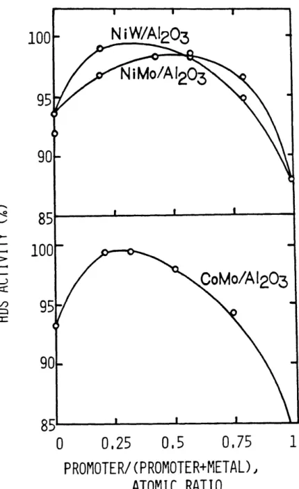
Page I-1 The effect of Promotor on HDS Activity. Pro- 38
motor: Co or Ni, Metal: Mo or W (Ahuja et al., 1970)
I-2 (a) The Correlation between S/Mo Ratio and HDS 41 Activity, (b) the correlation between S/Mo
Ratio and Pyridine Adsorbed (Okamoto et al., 1980; o-Preduced, a-oxide form, *-presulfided catalyst)
I-3 Hydrogenation Activity increates with the 43 Intensity of ESR signal of W
(Voorhoeve,1971)
I-4 Residence Time Distribution with or without 48 the Dilution of Catalyst Bed (van Dongen and
van Klinken, 1980)
II-1 Schematic Diagram of Experimental Apparatus 58 II-2 Liquid Feed Arrangement for the Trickle Bed 63
Reactor
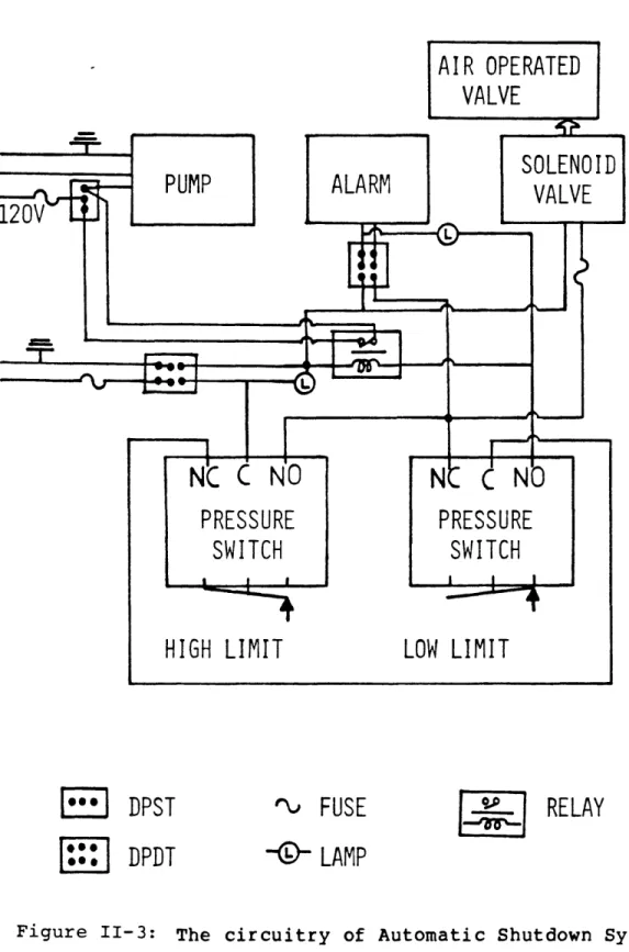
II-3 The circuitry of Automatic Shutdown System 67
II-4 Hydrogenation of d-hexadecene 73
II-5 (a) The GC Spectrum of the Liquid Carrier, (b) 75 The GC spectrum of a Liquid Carrier that
underwent Thermocracking at a Condition of 4200C, 0.25 minc/min Liquid Flow Rate and under H2 Flow
II-6 The GC Spectrum of Products from Quinoline 83 Hydrodenitrogenation
II-7 The GC Spectrum of Products from o- 84 Ethylaniline Hydrodenitrogenation
II-8 The GC Spectrum of Products from m-Ethylphenol 85 Hydrodeoxygenation
II-9 The GC spectrum of Products from o-Ethylphenol 86 Hydrrodeoxygenation
II-10 The GC Spectrum of Products from Benzofuran 87 II-11 The GC Spectrum of Products from Simultaneous 88
HDO/HDN of Benzylether and Quinoline
II-12 The Hydrodynamics of a Three Phase Cocarrent 95 Downflow Reactor (Froment and Bischoff, 1979;
Satterfield, 1975)
II-13 Quinoline Hydrodenitrogenation Influenced by 98 the Gas/Liquid Ratio
II-14 Product Distribution of Quinoline Hydrodeni- 99 trogenation by Using Various Gas/Liquid Ratio
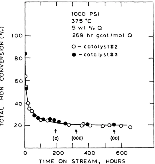
III-1 Catalyst Histories for catalyst #2 and # 3 112 III-2 Catalyst Activity Changes without Resulfida- 114
tion
III-3 Revised Reaction Network for Quinoline Hydro- 119 denitrogenation
III-4 The Total Ion Plot of GC/MS Analysis Accom- 121 panied with Structure Assignments for Products
from Quinoline Hydrodenitrogenation
III-5 Mass Spectrum of the Major Saturated Hydrocar- 124 bon, Identified as Propylcyclohexane
III-6 Mass Spectrum of the Isomer of Propylcyclohex- 125 ane, Identified as Methylpropylcyclopentane
III-7 Standard Mass Spectra of n-Butylcyclopentane, 126
1,2-methylpropylcyclopentane,n-propylcyclohexane, i-propylcyclohexane (Heller and Milne, 1978; Meyerson et al., 1963)
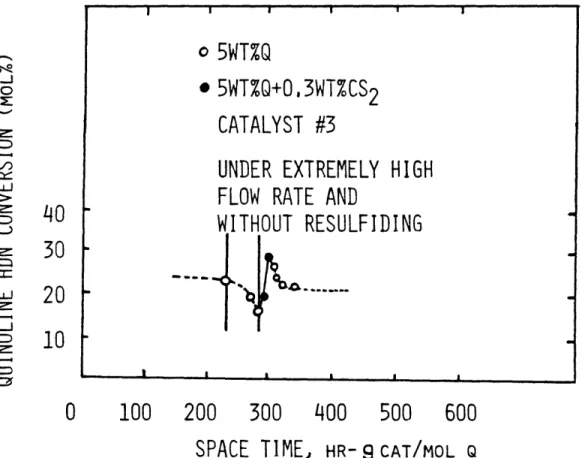
III-8 Mass Spectrum of 2-Propylcyclohexylamine 129 III-9 HDN Conversion of Quinoline is Essentially 142
Proportional to Space Time as Defined
III-10 Product Distribution of Hydrodenitrogenation, 144
III-11 Equilibrium Ratio of PyTHQ and Q is Essen- 145 tially the Same in Vapor Phase and Liquid
Phase
III-12 Simplified Quinoline Reaction Network in the 146 Kinetic Modelling
III-13 The Sectioning of Quinoline Reaction Network 152 in the Kinetic Modelling
III-14 Comparison of Langmuir-Hinshelwood Kinetic 156 Models for o-Propylaniline
III-15 Schemes Tried for Zone II in Modelling BzTHQ 159 Kinetic Data
III-16 Schemes Tried for Zone III in Modelling Quino- 163 line Kinetic Data (Rate Constants in Boxes are
Treated as Knowns in the Mathematic Manipula-tion)
III-17 The Arrhenius Plots of k and k2 for set (0), 168
(00), and (000)
III-18 The Arrhenius Plots of k5, k6 and k7 for set 169
(0), (00) and (000)
III-19 The Arrhenius Plots of k3 , k k8 and kg for 170
set (0), (00) and (000)
III-20 The Ratio of k8/k is the Same as the Concen- 171
tration Ratio of PyTHQ and Q at Equilibrium
-Set (0)
III-21 Comparisons between Simulated Product Distri- 172 butions and Experimental Data for Set (0)
III-22 Comparisons between Simulated Product Distri- 173 butions and Experimental Data for set (00)
III-23 Comparisons between Simulated Product Distri- 174 butions and Experimental Data for set (000)
III-24 The Ratio of k /k6 is Essentially the Same as 176 the Concentration Ratio of DHQ and BzTHQ at
Equilibrium - Set (0)
III-25 Comparisons of Quinoline HDN Results between 5 181 wt% Q Feed and 1 wt% Q Feed - Catalyst #2
III-26 Comparisons of Quinoline HDN Results between 5 182 wt% Q Feed and 1 wt% Q Feed - Catalyst #3
III-27 Product Distributions of Quinoline HDN in 185 Vapor Phase and Liquid Phase
IV-1 The Enhancement Effect of H2S on Quinoline HDN 191 IV-2 Product Distributions are Affected by the 192
Presence of H2S (Catalyst #3)
IV-3 Increase in Concentration above 1.5 wt% CS2 193
Shifts Intermediate Product Distribution Markedly, but with Little Effect on HDN Conversion
IV-4 The Enhancement Effect of H2S on Ring Isomeri- 195 zation
IV-5 The Effect of CS2 on HDN Conversion is Rever- 196 sible
IV-6 The Enhancement Effects of H2S are Similar in 199 Liquid and Vapor Phase Reactions
IV-7 Sample History of Set (0), (1), (2), (3) on 200 Catalyst #3
IV-8 The Arrhenius Plots of k and k2 for Set (0), 203
(1), (2) and (3)
IV-9 The Arrhenius Plots of k5 k6 and k7 for Set 204
(0), (1), (2) and (3)
IV-10 The Arrhenius Plots of k , k4, k8 and k for 205
set (0), (1), (2) and (3
IV-ll Comparisons between Simulated Product Distri- 206 bution and Experimental Data for Set (1)
IV-12 Comparisons between Simulated Product Distri- 207 bution and Experimental Data for Set (2)
IV-13 Comparisons between Simulated Product Distri- 208 bution and Experimental Data for Set (3)
IV-14 CS Reduced Hydrogenation and Dehydrogenation 209 Rate Constants
IV-15 CS2 Markedly Increases Hydrogenolysis Rate 210 Constants
IV-16 The Ratio of Hydrogenolysis Rate Constant to a 212 Hydrogenation Rate Constant is about
Propor-tional to CS2 Concentration
IV-17 H2S Does Not Effect Ratio of Saturated to 213
Unsaturated Hydrocarbon Products
IV-18 Tetralin Moderately Inhibits the HDN Reaction, 219 but its Hydrogenation Rate is Slow in
Tetralin/Quinoline Feed
IV-19 Quinoline Conversion Increases with Hydrogen 221 Pressure
IV-20 Equilibrium Value'of C TH/(CyTH Q + CQ) as a 222
Function of Hydrogen Pressure
IV-21 The Interaction of a H S Molecule with a Sul- 225 fur Vacancy on catalyst Surface
IV-22 The CS2 Effect on Catalyst 2 and 3 229
V-l Structures of Oxygen Compounds Studied 234 V-2 Hydrodeoxygenation of m-Ethylphenol alone or 240
in Presence of o-Ethylaniline (OEA) or of Quinoline (Q)
V-3 Distribution of Major Products from HDO of m- 241 Ethylphenol, Quinoline Present, 6.9 MPa and
375°C
V-4 Hydrodeoxygenation of o-Ethylphenol alone or 244 in Presence of o-Ethylaniline (OEA) or of
Quinoline (Q)
V-5 Distribution of Major Products from HDO of o- 245 Ethylphenol, Quinoline Present, 6.9 MPa and
V-6 Hydrodeoxygenation of Benzofuran alone or in 248 Presence of o-Ethylaniline (OEA) or of
Quino-line (Q)
v-7 Distribution of Major Products from HDO of 249 Benzofuran, Quinoline Present, 6.9 MPa and
3750C
V-8 HDO Reaction Network of Ethylphenols 254 V-9 HDO Reaction Network of Benzofuran 255 V-10 HDO Reaction Network of Benzylether 256 V-ll Oxygen Compounds Enhance HDN of Quinoline (Q) 258 V-12 m-Ethylphenol Alters the Distribution of 260
Intermediate Products in HDN of Quinoline (Q)
V-13 o-Ethylphenol Exerts Similar Effect on Quino- 261 line HDN as m-Ethylphenol
V-14 Benzofuran Exerts Similar Effect on Quinoline 262 HDN as m-Ethylphenol
V-15 Benzylether Exerts Similar Effect on Quinoline 263 HDN as m-Ethylphenol
V-16 Addition of m-Ethylphenol or Water Increases 265 the HDN of Quinoline, H2S Present
V-17 Phenols Increases the HDN of o-Ethylaniline 267 (OEA) but Benzofuran Decreases it, Numbers in
Parentheses are the % HDO of the Oxygen Com-pound
V-18 H-bonding between Nitrogen and Oxygen Com- 268 pounds
V-19 Enhancement of Quinoline HDN by m-Ethylphenol 272 or Water is Less in Absence of H2S
V-20 The Possible Interaction of a Water molecule
with a Surface Vacancy on Sulfided NiMo/A1203 274 Catalyst
V-21 In a Mixture the HDO of o-Ethylphenol is 277 Decreased Markedly and the HDN of
o-Ethylaniline is Increased Moderately, H2S Present
V-22 In a Mixture the HDO of Benzofuran is 278 Decreased and the HDN of Quinoline is
Increased
V-23 Relative Reactivity of Four Oxygen Compounds 279 in Presence of Quinoline
VI-1 Activity History of Six Catalyst Charges (See 286 Text)
VI-2 Presence of H S Increases HDN of Quinoline, 288 Catalyst #3 ad #6
VI-3 Presulfidation to Produce Lower S/Mo Ratios on 298 Catalyst Increases Thipohene HDS Activity.
*Catalyst Weight Taken to be 250 mg
VI-4 H2S Increases the HDN of Quinoline but Inhi- 303 bits that of o-Ethylaniline
VI-5 Thiophene HDS Reaction Network Proposed by 305 Desikan and Amberg (1964)
VI-6 Effects of H2S Partial Pressure on Thiophenol 308 HDS and Olefln Hydrogenation. (1) Satterfield
and Roberts, 1968; (2) Lee and Butt, 1977; (3) Ramachandran and Massoth, 1981
VI-7 Dibenzothiophene Reaction Network Proposed by 310 Broderick and Gates (1981)
LIST OF TABLES
Page I-1 Elemental Analysis of Synthetic Liquids and 20
Petroleum Crudes
I-2 Conditions for Hydrotreating Processes 23 I-3 Representative Nitrogen Compounds in Syncrudes 25 I-4 (a) Representative Oxygen Compounds in Syn- 27
crudes (b) Representative Sulfur Compounds in Syncrudes
I-5 Properties of Typical Commercial Hydrotreating 37 Catalysts
II-1 Thermocracking of Liquid Carrier 77 II-2 Analytical Conditions for Carbowax 20M Capil- 81
lary Column
II-3 Analytical Conditions for SE-54 Capillary 82 Column
II-4 Typical Properties of American Cyanamid AERO 91 HDS-3A CATALYST (NiMo/A1203)
II-5 Typical Gas and Liquid Flow Rates Used in 94 Trickle Bed Operation
III-1 Experimental Conditions for Liquid Phase 116 Quinoline HDS without H2S Present
III-2 Heavy Products from Quinoline HDN Reaction, 133 Identified by GC/MS
III-3 Equilibrium Constants of Six Hydrogen Donor 137 Reactions
III-4 Tests for Homogeneous Reactions 139 III-5 Homogeneous Reactions of Quinoline 141 III-6 Basicity of Reaction Species in Quinoline HDN 150
III-7 Hydrodenitrogenation of Alkylaniline 155 III-8 Detailed Procedures in Modelling Quinoline 162
Kinetic Data for Set (0) at 3750C
III-9 Rate Constants of Quinoline Reaction Network 166 for Set (0), (00) and (000)
III-10 (a) Resonance Energy of Reaction Intermediate, 178 (b) Change in Resonance Energy for Special
Reactions
III-11 Comparison of Kinetic Rate Constants in Vapor 186 Phase and Liquid Phase Reaction
IV-1 Experimental Conditions for Liquid Phase 198 Quinoline HDN with H2S Present
IV-2 Rate Constants of Quinoline Reaction Network 202 for Set (0), (1), (2) and (3)
IV-3 Activation Energies of Quinoline Reaction Net- 215 work with and without H2S Present
V-1 Detailed Reaction Conditions for Simultaneous 237 HDO/HDN Reaction
V-2 Product Distribution from m-Ethylphenol HDO 239 Reaction
V-3 Product Distribution from o-Ethylphenol HDO 243 Reaction
V-4 Product Distribution from Benzofuran HDO Reac- 247 tion
V-5 Basicities of Selected Model Compounds in HDO 251 and HDN Reactions
Effects of Sulfidation Treatment on S/Mo Ratio 293 VI-1
Introduction and Background
I.1. Introduction
Because of the depletion of conventional petroleum
resources, synthetic liquid fuels derived from coal, oil shale and tar sands will be assuming a role of increasing importance in the future. Such synthetic feedstocks and heavier
petroleum fractions are characterized by high concentrations of heteroatoms such as sulfur, nitrogen and oxygen.
Table I-1 illustrates typical nitrogen, sulfur and oxygen contents of some representative synthetic liquid fuels, light petroleum crude and heavy residuum. Some coal liquids, shale oil and tar sand oil contain ten times as much nitrogen as is present in most crude petroleum refined today. Besides, coal
liquids also contain substantial amounts of oxygen species. Hydrotreating processes are used in petroleum refining to remove the heteroatoms such as sulfur, oxygen, nitrogen and metals from feedstocks. Since sulfur is the dominating
heteroatom in petroleum feedstocks, catalytic hydrodesulfuri-zation (HDS) has been an important commercial process for
sometime. Such processes and catalysts are optimized for sul-fur removal, though hydrodenitrogenation (HDN), hydrodeoxyge-nation (HDO), hydrocracking and hydrogehydrodeoxyge-nation all occur
-19-O Oa C de -{ de ,O O 0 11q 0
0
0
coo
0 0 N N 0 0o
o( u3 0 o o H' N 0 ,i n co o * 0 4 * (Y01-
r- 0 r- L) L108C
dP dP dP 4-3 4-3 4-3 4z m o) r-0~H Cd 43 a) a) r-q (a U H4 U) ) o E o $4 aD u C $4 > N 03 (N _ _ _ 4_ _4 U) a) E a) 4J U) 'U .-I .1-H4
U U) :. U) 4a) w a) ro E 0 ro o H 4) > U) U o0 U U) ____ _ _ _ _ C r-UI) C LA-simultaneously to various degrees.
Nitrogen compounds in fuels may result in poor color and instability and contribute to NOx emission on combustion. In
refining feedstocks nitrogen compounds poison the acidic catalysts used in reforming, cracking and hydrocracking
processes. Catalytic reforming processes require feedstocks containing not more than a few ppm nitrogen, and catalytic cracking feedstocks can tolerate only a few hundred ppm nitro-gen. Furthermore, some heterocyclic nitrogen compounds may be carcinogenic.
It is not clear whether the removal of oxygen species is required during this hydrotreating in order to achieve desired product specifications but in any event if oxygen species are
present, they may react and because of the high oxygen content of coal liquids this can cause significant additional hydrogen consumption and may complicate nitrogen removal.
Generally nitrogen compounds are more resistant to remo-val than sulfur compounds of similar molecular weight under comparable conditions. Low nitrogen contents can be obtained by very severe HDN treatment, which requires a high hydrogen consumption and can be costly. The existing hydrotreating processes and catalysts, which have been developed for HDS reaction, may not be optimum for HDN reaction.
1.2. Processes
Typically, the sulfur and nitrogen contents are lowered by a hydrotreating process in a trickle bed reactor at hydro-gen pressure in the range of 3.45 Mpa (500 psi) to 13.8 Mpa
(2000 psi) and temperature in the range of 3000C to 4200C. Usually a catalyst of CoMo, NiMo or NiW supported on alumina is employed. In general, the operating conditions are much more severe for synthetic fuels and heavy residua than for light petroleum feedstocks, as shown in Table I-2; they
require higher temperature and pressure, and consume more hydrogen. Upon removing heteroatoms, hydrogen sulfide, ammonia or water is ultimately formed; also, the highly aromatic molecules in coal liquids can also be hydrogenated.
In the industrial operation, the temperature of a trickle bed reactor is gradually increased with time to compensate for catalyst deactivation and to maintain constant conversion. Usually the catalyst is regenerated by burning off the coke. The catalyst deactivation can be extremely severe with coal
liquids because of their high coke-forming tendencies. 1.3. Characterization of Heteroatoms in Syncrudes
The nature of nitrogen and oxygen compounds in petroleum is summarized by Snyder (1970). It was found that similar types of nitrogen-containing compounds are present in syn-thetic fuels as well (Aczel and Lumpkin, 1977; Qader et al.,
0
No
o
o
0
N 0
0
o cu O 0O~a 0 o o I'do
o
o oo
0
LA0
0
Cr) No
o
I Io
0 0 LAo
o
o LA I Io
0 0 00
Io
00
0
0 CN C; I oo
00
0
0
I'-
00
0
0
0
I I CN 0 u) N I H {D - 03 : -- 0r 43 E-, -7 OrI r4 a) U) -H a a)a)
___d
NN 10 -I X Ut Cdr 3 :> Url C Cd 0 a _- N m -HI .
1 0 U -a) 0 U) rd to, .4 Cd z a, U) U) o3 0 h .4 "4 0C 4D) a) 0 E-4 -H 4-) ou
1969; White et al., 1978; Paudler et al., 1979; Scheppele et al., 1977). Nitrogen is largely in the form of heterocyclic compounds having five or six membered rings such as pyridines, quinolines, acridines, pyrroles, indoles, and carbazoles; it is also in the form of aromatic amines and aliphatic amines, as shown in Table I-3.
Aczel and Lumpkin (1979) further indicated that the
heteroaromatic components in cool liquids possed one-to-eight ring condensed aromatic skeletons, associated with functional groups including pyrrolic, pyridinic, thiophenic, furanic, hydroxylic, and carboxylic groups; and that compounds with more than one functional group are also present in coal
liquids. Buchanan et al. (1980) found primary aromatic amines and azaarenes to be the major nitrogen compounds in coal
liquids. The aromatic amines range in size from one to three aromatic rings and with alkyl substitution up to six carbons, in which the degree of alkyl substitution decreases with an increase in the number of aromatic rings. Azaarenes range in size from two to six rings including, for example, quinolines, dibenzoquinolines, azafluorenes, azabenzopyrenes. Buchanan et al. also found that shale oil contain less primary aromatic amine and the azaarenes in shale oil are generally smaller in ring size than those observed in the coal derived subfrac-tions.
Table I-3
Representative Nitrogen Compounds in Synthetic Fuels
otczo
Pyridine Quinoline Acridine
CNrbzl
Carbazole Azapyrene AzacholanthreneC
3,5-Methylbutylaniline Pyrrole Indole NPhenol derivatives predominate among the oxygen compounds in liquid fuels derived from coal, oil shale and tar sand. For example Ignasiak et al. (1977) reported that 75% of the oxygen present in an Athabasca asphaltene was in the form of hydroxyl functions. In a detailed analysis of an anthracene oil, Scheppele et al. (1981) reported that 81% of the acids were hydroxylated aromatics. Furans, Carbonyls and carboxyl groups are also found. Representative ones are shown in Table
I-4.
The sulfur contents are low in synthetic crudes largely due to the desulfurization in the liquefaction or retorting process. The sulfur compounds appear mainly as the thiophenic
type in syncrudes, as shown in Table I-4.
I.4. Reactions on Hydrotreating Catalysts
Hydrotreating studies have been conducted with actual feedstocks, or with model compounds dissolved in simulated feedstocks. Most commonly a feedstock of interest is
hydroprocessed and the percent removal of sulfur, nitrogen and oxygen is reported as a function of reaction conditions.
Often such studies are empirical and little fundamental under-standing is gained about the nature of the reaction occurring. Model compound studies on HDN, HDS and HDO not only lead to a fundamental understanding of the reactions themselves but also shed light on the development of improved catalysts and
Table I-4
A.Representative Oxygen Compounds in Synthetic Fuels
Dihydroxylfluorene
,L
C3H 7
CH
3Benzonaphthofuran
KŽC
COOH
°
B.Representative Sulfur Compounds in Synthetic Fuels
H
Dibenzothiophene
Benzopyrenothiol
s---processes. In this thesis only the relevant model compound studies are reviewed.
I.4.1. Hydrodesulfurization (HDS)
The literature concerning HDS reactions has been reviewed in detail by Schuit and Gates (1973) and by Schuman and Shalit
(1970). The results on HDS reactions of thiophene, ben-zothiophene and dibenben-zothiophene are briefly mentioned here, which will be helpful in the understanding of catalytic sites on hydrotreating catalysts.
Owens and Amberg (1961) studied the thiophene HDS reac-tion over chromia and cobalt molybdate and determined the
relative rates for various steps in its reaction network. The initial step in HDS is the direct extrusion of sulfur to form butadiene which undergoes hydrogenation to 1-butene rapidly. 1-Butene is then isomerized to cis and trans 2-butene, or further hydrogenated to butane, as shown in pathway A in the following:
PATHWAY (A)
PW% /
SThe rate-limiting step is the hydrogenation of butene. Later Desikan and Amberg (1964) studied the HDS reaction of tetrahy-drothiophene and suggested that thiophene can also undergo hydrodesulfurization through a minor pathway B by hydrogena-tion of its ring prior hydrogenolysis of hydrothiophene.
Givens and Venuto (1970) reported the HDS reaction net-work of benzothiophene over CoMo/A1203 : benzothiophene is
hydrogenated on its thiophenic ring to form
dihydroben-zothiophene, prior to the hydrogenolysis of C-S bond to form ethylbenzene. Furimsky and Amberg (1976) found Styrene among the products resulting from the HDS reaction of benzothiophene on an unsupported MoS2 catalyst. The authors therefore argued that benzothiophene should undergo direct sulfur extrusion on supported cobalt molybdate as well, but the intermediate
styrene is then hydrogenated rapidly to ethylbenzene and left no trace in the final product stream.
The HDS studies on dibenzothiophene (Houalla et al., 1978; Broderick and Gates, 1981) clearly demonstrated that both the hydrogenation of thiophenic ring and the direct extrusion of sulfur occur on CoMo/A1 203 as indicated in the
_
r . __. ... ... ] ...
_ -- _---I II ~L '
\\l
1~
_
X,.
....
|~ ~
~
~
~
...~
~
ll(B... l~~~~~~~~~~' ...' ,__
In pathway A, sulfur is directly removed from dibenzothiophene resulting in diphenyl, while dibenzothiophene is hydrogenated to form tetrahydrodibenzothiophene through pathway B.
Tetrahydrodibenzothiophene is in equilibrium with hexahydrodi-benzothiophene which in turn loses sulfur and is converted to phenylcyclohexane. The unambiguous result of the two reaction pathways is due to the fact that biphenyl, the product from
direct sulfur extrusion, is quite stable against further hydrogenation and remains in the product stream.
1.4.2. Hydrodenitrogenation (HDN)
The hydrodenitrogenation of heterocyclic nitrogen com-pounds occurs via a complex reaction network involving
hydrogenation of the heterocyclic rings followed by carbon-nitrogen bond scission, in contrast to hydrodesulfurization which involves largely direct extrusion of sulfur from
Most of the work on monocyclic nitrogen compounds has been done with pyridine, while pyrrole has seldom been used because of its thermal instability. The HDN reaction network
of pyridine was studied by McIlvried (1971) on sulfided
CoNiMo/A1 203 and by Sonnemans et al. (1973, 1974) on reduced
Mo/A1203, as shown in the following:
Pyridine is hydrogenated to piperidine following hydrogeno-lysis of the C-N bond to form pentane. Sonnemans et al. also found a significant amoung of N-pentyl piperidine resulting from an alklyl transfer reaction.
Doelman and Vlugter (1963) studied the quinoline HDN reaction over a prereduced CoMo/A1203, and concluded that
rapid hydrogenation of quinoline on the heterocyclic ring occurs first, followed by ring rupture and deamination. Recently Satterfield and coworkers (1981) carried on
research on quinoline HDN in a vapor phase flow reactor using sulfided NiMo/A1 203. Shih et al. (1977) investigated the same
reaction in a bath reactor also using sulfided NiMo/A1203. Both reported a similar and more complete reaction network for quinoline HDN.
m)
X
HNH 2J
+2H1 i 3H2| |~
OC3H?
C3H7
_ +NH 3
Under all reactions investigated, quinoline is rapidly hydro-genated to py-tetrahydroquinoline reaching thermodynamic
equilibrium. Saturation of the heterocyclic ring is required before hydrogenolysis of C-N bonds and nitrogen removal reac-tions can process. The aromatic ring in quinoline can also be saturated, either as the initial reaction step or during the nitrogen removal process. The major hydrocarbon product is propylcyclohexane.
The thermodynamics of HDN reactions have been reported (Cocchetto and Satterfield, 1976). Equilibrium constants for HDN reactions of various heterocyclic nitrogen compounds were estimated.
1.4.3. Hydrodeoxygenation (HDO)
An extensive literature exists on hydrodesulfurization (HDS), a lesser amount on hydrodenitrogenation (HDN), but relatively little attention has been paid to how oxygen species may affect HDS, HDN, or the nature of the reaction networks of hydrodeoxygenation. Furimsky (1978, 1979) studied the hydrodeoxygenation of a heavy hydrocracked gas oil from hydrocracking of Athabasca bitumen, Qader et al. (1968) of a low temperature coal, Sullivan et al. (1978) of shale oils. Badilla-Ohlbaum et al. (1979,a,b) and Rollmann (1977) studied the simultaneous HDS, HDN, and HDO reactions occurring in a mixture of several model compounds. In both cases dibenzo-furan was used to represent the oxygen compound in the model feedstock. Rollmann further determined the reactivity of several other phenol and furan derivatives by substituting them one at a time for dibenzofuran in the model mixture. Recently Krishnamurthy et al. (1981) did a detailed kinetic study on the HDO of dibenzofuran. Weisser and Landa (1973)
reviewed the earlier literature on hydrogenation of alcohols, ketones, aldehydes, and phenols over sulfide catalysts.
In hydrodeoxygenation of phenol over a MoS2 catalyst (Weisser and Landa, 1973), hydrogenation of the phenoic ben-zene ring is far more dominant than hydrogenolysis of the phenolic hydroxyl group at high pressures (about 10 MPa) and the dehydration of cyclohexyl alcohol is by far the most rapid
reaction under severe reaction conditions. Rollmann (1977) proposed similar routes for the alkylphenols which he studied on sulfided CoMo/A1203.
1.5. Reaction Kinetics
Most of the kinetic studies on HDN have employed a pseudo first order kinetic model and reported a decrease of the first order rate constant with increased initial nitrogen concentra-tion (Cox and Berg, 1962; Flinn et al., 1963; Sonnemans et al., 1973; Shih et al., 1977). Such behavior suggested that the adsorption of nitrogen compound on the catalyst surface inhibits the reaction rate and can be interpreted in terms of a Langmuir-Hinshelwood kinetic model.
Several forms of Langmuir-Hinshelwood rate expressions have been used in modelling pyridine HDN. McIlvried (1971) fit his kinetic data by taking ammonia as the only strongly adsorbed compound on a sulfided NiCoMo/A1203.
Goudriaan (1974) found that pyridine HDN on a sulfided CoMo/A1203 is best modelled by the following equation
1 + KNPN
where Ppyridine is the partial pressure of pyridine, PN is the sum of partial pressures of all nitrogen compounds, and KN is
the effective averaged adsorption constant for pyridine and
its reaction products.
Indeed, there is evidence that the strength of adsorption of nitrogen compounds may vary significantly. In a study of shale oil HDN, Koros et al., (1967) found that the indole type compounds are less reactive than quinoline-type, but that
indole is more reactive than quinoline when studied individu-ally. This can be explained by competitative adsorption
between quinoline and indole; the more basic quinoline is pre-ferentially adsorbed and reacted.
Satterfield and coworkers (1981) used the Langmuir-Hinshelwood rate expression to model each individual step in the quinoline HDN reaction network for their vapor phase study on sulfieded NiMo/A1 203. The adsorption of all the nitrogen
compounds in the network, including reactant quinoline, final product ammonia, and reactin intermediates, were included in
the Langmuir-Hinshelwood expressions. Assumptions were made to simplify the modelling. The secondary amines
Py-tetrahydroquinoline and decahydroquinoline are assumed to
adsorb equally strongly. Equal adsorptivities of the aromatic amines are assumed for quinoline, Bz-tetrahydroquinoline and o-propylaniline.
1.6.1. Composition
The catalyst typically consists of CoMo, NiMo or NiW sup-ported on Y-alumina, in which MoO3 or W03 is the main consti-tuent, and CoO or NiO serves as the promotor. CoMo/A1203 catalyst is normally used for HDS reactions while NiMo/A1203 are more active for HDN reaction (Ahuja et al., 1970; Shih et al., 1978) because nickel has higher hydrogenation activity.
The industrial hydrotreating catalysts contain 3 to 5 wt% CoO or NiO, 12 to 15 wt% MoO3, and very small amount of minor promotors or impurities such as silicate, phosphate, sulfate, and sodium. The weight percent of WO3 in commercial hydro-treating catalyst is higher than that of MoO3 for tungsten has a greater atomic weight than molybdenum, 232 versus 144. As shown in Table I-5, the major chemical compositions of commer-cial hydrotreating catalysts do not vary much. Many research-ers have related the relative amount of promoter (Ni or Co) and main metal (Mo or W) to the catalyst activity. One typi-cal study by Ahuja et al., (1970) is shown in Fig. I-1, in which HDS activity goes through a maximum value as the amount of promotor on the catalyst increases. Indeed most of the commercial hydrotreating catalyst have the atomic ratio of Co/Co+Mo (or Ni/Ni+Mo, or Ni/Ni+W) in a range of 0.3 to 0.5 as shown in Table I-5.
The physical properties of commercial hydrotreating
0 co Ln Ln r 00 U) I I LA o en N (N 0O r4 4O 0 'IO
0
U)o
d' ' CN 0u0
o CO -' Co LA -4 0 .H *Ho,s Ln0
003 O 4 O 1 C rc ro dP :3 i o m(0 N 0 0 i, a) 'H (N q.4 (D O3 O O o Nr +d-o
o
c -0
c;o
-N 0 O 0 .14 Cd 4C) 0 4Ju .150
Ln CN 0 mO 1--(N In O o~o
0
3
,-4 Z O30
N -i 0 : -0u
\o Cr) 1-4 m (N Oz rC)Z 3 Q ln _ CdQod-rrj Id n Cd O 1-4 C3 U C ~LA 1-4 cc N co
(4 '
r 1--Ln ,r 0 U) .3 1-4 4.,Cd U 4-) Cd ao 0 O 4 Cd ro '4-a) a) 0 -4 04 rr] E-·rA (1 . LA cN1--0
54 0 0 0 a 0 4Z C4 E-4Z_ _ 0Q .. .CdH -, g.H ·rd dr _ _V _0
14 00
0 u .o9 -4 r, 0 U I
-
I-I= 0 0.25 0.5 0,75 PROMOTER/(PROMOTER+METAL), ATOMIC RATIOFigure 1-1: The effect of Promotor on HDS Activity. Promotor: Co or Ni, Metal: Mo or W
(Ahuja et al., 1970)
vary significantly. Katzer and Sivasubramanian (1979) have reviewed the effect of physical properties of the support on catalytic hydrodenitrogenation. The commercial hydrotreating catalyst may differ from each other greatly in the minor pro-motor added.
1.6.2. Structure
Much research has been carried out on the structure of hydrotreating catalysts, particularly of CoMo/A1203.
Tech-niques such as x-ray photoelectron spectroscopy (XPS), x-ray diffraction (XRD), electron spin resonance (ESR), infrared spectroscopy (IR), edge x-ray absorption fine structure
(EXAFS) have been used to study the structure of molybdenum and cobalt on the catalyst surface, the role of promoter cobalt to the catalyst, and the interaction of cobalt and molybdenum with alumina support. Recently the subjects have
been reviewed by Grange (1980), Furimsky (1980), Ratnasamy and Sivasanker (1980), and Massoth (1978).
The sulfide form of hydrotreating catalyst may have quite a different surface structure from its oxide precusor, and it is also much more active than the oxide precusor for the HDS, HDN and HDO reactions. In the industrial operation, the
catalyst is converted to sulfide form in situ either by a flow of H2S-H2 or by a feedstock containing sulfur compounds.
Here only the structure of sulfide catalyst is briefly reviewed. When a commercial HDS catalyst, typically consist-ing of CoO in the range of 3-5% and MoO3 in the range of 12-15%, is sulfided, the major part of the molybdenum is con-verted to MoS2 and CoO is transformed to Co and Co8S9
(Patter-son et al., 1976; Declerck-Grimee et al., 1978; Brinen and Armstrong, 1978). Smaller amounts of oxysulfides, polymeric
sulfur, and Mo(V) and Mo(VI) may also be present. It has been demonstrated that MoS2 exists in a two dimensional form on an
alumina support (Brinen and Armstrong, 1978; Pollack et al., 1979). The interaction of MoS2 with support is weaker than that of MoO3 with support.
1.6.3. S/Mo Ratio and HDS Activity
Most of the studies to relate the structure of a catalyst to catalytic activity were done on the thiophene HDS reaction over a Mo/A1203 catalyst. Mossoth and Kibby (1977) and
Okamoto et al., (1980a, 1980b) studied the relationship between the HDS activity and the degree of sulfidation of Mo/A1203. Okamoto et al. demonstrated that the HDS activity depended! simply on the degree of sulfidation of molybdenum determined by XPS, for the catalysts in oxide form, reduced form or presulfided form, as shown in Fig. I-2(a). The max-imum HDS activity was obtained when the atomic ratio of S/Mo is about 1. They also found a similar relationship between the amount of pyridine adsorbed on catalyst and the degree of
1,0 2.0 SULFUR/MoLYBDENUM ATOMIC RATIO
Figure 1-2: (a) The Correlation between S/Mo Ratio and HDS Activity, (b) the correlation between S/Mo Ratio and Pyridine Adsorbed (Okamoto et al., 1980; o-Preduced, o-oxide form, -presulfided
catalyst)
0.4
1-o
0
I-0
Z: 1-0,3 CD UL ., LL 0-cn C,2 14c)
XIs
C) C,)=
12 10 8 6 4 2 0sulfidation of molybdenum, as shown in Fig. I-2(b). It was concluded that a partially sulfided Mo/A1203 catalyst, at a ratio S/Mo of 1, has a greater capacity for pyridine adsorp-tion and a greater activity for HDS reacadsorp-tion.
I.6.4. Catalyst Sites
The catalytic sites on hydrotreating catalyst have been suggested from various surface investigation and kinetic results.
ESR studies of sulfided Mo/A1203 and NoMo/A1203 suggested the existence of surface vacancies on these catalysts (konings et al., 1978, 1981). Voorhoeve (1971) related benzene
hydrogenation and the ESR intensities of W+ 3 ions in a series of sulfided NiW/A1203, as shown in Fig. I-3. The good corre-lation suggested that hydrogenation reaction occurs on surface anion vacancies which are formed by the loss of sulfur from WS2 structure. Lipsch and Schuit (1969) proposed a mechanism for thiophene hydrodesulfurization on the oxide form of
CoMo/A1203 through the interaction of thiophene with surface
vacancy. Tanaka and Okuhara (1977) suggested a correlation between the coordination on the surface and the hydrogenation and isomerization of olefins. It is often assumed that hydro-gen and the heteroatom compounds adsorb on different catalyst sites. On sulfide catalysts, hydrogen is believed to adsorbed dissociatively on sulfur atoms, forming hydrosulfide groups
1 101 Lr
I
<10°
H -) L 10-1 LLJ PJ10-2
Z
CD 10-3 C= 10° 101 102 103INTENSITY OF ESR SIGNAL/ 9 CATALYST, ARBITRARY UNIT Figure I-3: Hydrogenation Activity increases with the
Intensity of ESR signal of W
(Voorhoeve, 1971)
I I ,
0
I(Weisser and Landa, 1973, p.78; Massoth, 1975). The active catalyst sites are most likely associated with defects in the metal sulfides.
Owens and Amberg (1961) observed that H2S inhibited
hydrogenation of butene and thiophene hydrogenolysis, and that H2S had very little effect on cis-trans isomerization, double bond shifts, and butadiene conversion to butene. The results suggested that more than one kind of sites is involved in hydrodesulfurizaition.
Desikan and Amberg (1964) studied the poisoning effect of pyridine on thiophene hydrodesulfurization, and suggested two kinds of catalytic sites on CoMo/A1203. Site I is responsible for olefin hydrogenation and thiophene HDS, and has strong affinity for thiophene and pyridine; site II is weak electro-philic and facilitates hydrogenolysis of hydrothiophenes.
From the adsorption study, Lipsch and Schuit (1969) con-cluded that pyridine is adsorbed on two types of sites on
CoMo/A1203, and suggested that one type is related to molybde-num and has hydrogenation and hydrodesulfurization activity while the other type is associated with support and does not have catalytic function. However the study was done on the oxide form of CoMo/A1203.
Later Satterfield et al. (1975) also proposed two cata-lytic sites on CoMo/A1203 in their work of simultaneous
sensitive to nitrogen base; site II is much less active for HDS, and less susceptible to pyridine poisoning.
1.7. Trickle Bed Reactor
Trickle bed reactors have been developed by the petroleum industry for hydrodesulfurization, hydrocracking, and hydro-treating of various petroleum fractions of relatively high boiling point. A trickle bed reactor can offer several
advan-tages. In comparison to slurry reactors, it approaches plug-flow behavior and the low ratio of liquid to catalyst in the
reactor minimizes the extent of homogeneous reaction. In com-parison to vapor-phase operation of a fixed bed, it provides
significant energy savings. I.7.1. Hydrodynamics
For cocurrent gas-liquid downflow over a packed bed, various flow regimes such as trickle-flow, pulsed flow, spray
flow, and bubble flow may occur. The hydrodynamics of a trickle bed reactor depend on the following factors:
(1) Gas and liquid flow rates,
(2) Size and shape of the catalyst particles, (3) Fluid and catalyst wetting characteristics,
(4) Fluid properties such as viscosity, density, and surface tension,
(5) Liquid distributor.
At sufficiently low liquid and gas flow rates, the flow pattern is in the trickle-flow regime, in which the liquid
trickles over the packing in a laminar film or in rivulets, and the gas flows continuously through the voids of the bed. As gas and/or liquid flow rates are increased, one encounters pulsing flow, in which gas-rich and liquid-rich slugs pass through the catalyst more or less alternately. Most commer-cial operations are carried out in the trickle-flow or pulsed flow regime.
The hydrodynamics of trickle bed reactors have been
extensively studied but are quite complicated. Pressure drop, hold-ups and residence time distribution have been measured by many authors. The subject is reviewed by Satterfield (1975) and discussed in the book by Shah (1979).
1.7.2. Effective Catalyst Wetting
The effectiveness of catalyst wetting depends on many factors. In commercial operation nearly complete wetting is reached when the liquid flow rate is increased to a value in the range of about 1 to 5 kg/m2s. In laboratory-scale trickle bed reactors the liquid flow rates are much lower than this. It has been observed that in some cases the reaction rate in the large pilot plant is about twice of that in a laboratory unit (Weekman, 1976). Many studies on laboratory-scale
trickle bed reactors have been suspect because the low liquid flow rate can give rise to serious flow channeling and hence to inefficient use of the catalyst.
1.7.3. Catalyst Dilution in a Laboratory-Scale Trickle Bed Reactor
For kinetic studies, essentially a plug flow is desired for the liquid phase in a trickle bed reactor.
Catalyst dilution techniques developed by Akzo Chemie (de Bruijn, 1977) and Shell Laboratorium (van Klinken and van
Dongen, 1980) make it possible now to obtain meaningful data at very low liquid flow rates in a trickle bed reactor. The
technique consists essentially of careful packing of the catalyst bed with finely divided inert material and choosing the proper sizes of catalyst particles and inert particles.
Van Klinken and van Dongen measured the residence time distribution of the liquid flow in a trickle bed reactor by radioactive tracer. They found that the residence time is increased, and thus the liquid hold-up is increased, if the catalyst bed (particle size 1.5 mm) is diluted with fine inert particles of 0.2 mm diameter, as shown in Fig. I-4. From the
test of hydrodenitrogenation of a vacuum distillate under industrial conditions, it was concluded that the dilution of the catalyst bed substantially reduces axial dispersion of the reactor to the extent that liquid plug flow can be assumed.
z
0
b-4I-z
z
_J0
20
40
60
RESIDENCE TIME, MIN
Figure 1-4: Residence Time Distribution with or without the Dilution of Catalyst Bed (van Dongen and van Klinken, 1980)
The much higher liquid hold-up in the diluted beds leads to improved wetting and utilization of the catalyst particles. 1.8. Thesis Objectives
The ultimate goal is to have a fundamental understanding of the HDS, HDN, and HDO reactions as well as of the
hydro-treating catalysts, with a view to improve the catalysts and processes for future utilization of the synthetic fuels. This
thesis focusses on the following five subjects.
I.8.1. Design a Laboratory-Scale Trickle Bed Reactor
The conditions of hydrotreating utilized in industrial practice are (1) steady-state operation, (2) two-phase flow in a trickle bed reactor, (3) 350-4500C and (4) 6.9-13.8 Mpa. The majority of the laboratory experiments obtained to date have used a vapor-phase or a liquid phase flow reactor at
steady state, or a liquid phase, batch autoclave reactor. Each of these systems has potential pitfalls when extrapolat-ing results to industrial conditions.
The vapor-phase, flow reactor has two major difficulties: (i) If high molecular weight compounds are formed as inter-mediates in HDN, they will tend to build up on the catalyst in a vapor-phase reactor, whereas they may more readily desorb by dissolution into the liquid phase in a trickle-bed reactor.
be different in the vapor and liquid phase because the pres-ence of a liquid solvent may modify the activity of the
solutes.
The liquid phase flow reactor has a limited source of hydrogen which is presaturated in the liquid prior to the
reaction. The concentration of reactant is restricted by the limited amount of hydrogen presaturated in the liquid if the reaction is carried under a condition having hydrogen
stoichiometrically in excess. For example, the concentration of quinoline cannot be higher than 1 wt% corresponding to a value less than 0.1 wt% of nitrogen, which is lower than the typical nitrogen content in synthetical fuels and heavy resi-dua. For a study of a mixture of model compounds, even lower concentrations have to be used.
The liquid phase batch autoclave reactor does not have these problems, but it has others which may be more limiting in extrapolating results. It has been shown that the rate of HDN and HDS varies with time when reactor is started. This initial transient phenomenon is due to changes in the
catalyst. Such transients in the liquid batch system imply that the kinetics observed does not reflect the steady-state kinetics. Moreover, the high ratio of liquid to solid in an autoclave may magnify homogeneous thermal processes which would not be significant in a trickle-bed reactor.
Based on the dilution technique developed by van Dongen and van Klinken a laboratory trickle bed reactor was built, and tested to ensure a homogeneous liquid distribution over the catalyst bed. Essentially a liquid plug flow is assumed for the kinetic study of quinoline HDN.
1.8.2. Quinoline HDN in a Trickle Bed Reactor
The catalytic hydrodenitrogenation of quinoline has been studied in a vapor phase flow reactor (Satterfield and Coc-chetto, 1981). In this thesis quinoline HDN in liquid phase is investigated in great detail in a trickle bed reactor under the conditions used in industrial practice. A complete quini-line HDN reaction network were studied, including the ring isomerization of a hydrocarbon product and the formation of heavy molecular weight compounds. A model is developed to understand each reaction step in the reaction network kineti-cally.
The reaction network of quinoline HDN in the liquid phase is compared with that of in the vapor phase, under the same temperature, pressure and catalyst. The detailed kinetic stu-dies provides a basis for characterizing similarities and
differences between the same reaction as carried out in the vapor phase and liquid phase. The HDN reactions of alkylani-lines are also studied to investigate the effect of homologue and steric hindrance on hydrodenitrogenation.
1.8.3. The Effect of H2S on Quinoline HDN and Selectivity of NiMo/A1203 Catalyst
In previous vapor phase studies, it was shown that the rate of catalytic hydrodenitrogenation of quinoline is
increased in the presence of H2S, and reaches a plateau when H2S appears in an equimolar amount as quinoline (Satterfield and GUltekin, 1981). In their kinetic analysis, by using equimolar quantities of H2S and quinoline in the vapor phase it is found that H2S slightly inhibits hydrogenation while significantly enhancing hydrogenolysis in quinoline HDN.
In the present work the effect of H2S on quinoline HDN in the liquid phase is explored. Various concentrations of CS2 are added to feed in the kinetic study in order to understand how H2S affects the selectivity between hydrogenation and
hydrogenolysis the quinoline reaction network, and to investi-gate whether beyond certain concentration, H2S exerts no
further influences on such reaction. The nature of catalyst sites is proposed to explain the changes in selectivity due to the presence of H2S under reaction conditions.
1.8.4. Simultaneous HDO and HDN of Model Compounds
Upon reacting the heteroatoms in hydroprocessing, hydro-gen sulfide, ammonia and water are ultimately formed. The effect of water vapor on sulfide catalysts is not yet clear. Lipsch and Schuit(1969)reported a poisoning effect of water on the oxide form of cobalt molybdena catalyst. Satterfield and
Carter (1981) found that 13.3 kPa of water in a hydrogen pres-sure of 6.9 Mpa exerted little influence on quinoline HDN in the vapor phase over a sulfided nickel molybdena catalyst, but with no hydrogen sulfide added to the feed. In a brief study with a sulfided CoMo/A1203 catalyst at 3000C and 7.3 Mpa and in the presence of 200 kPa of H2S Goudriaan (1974) reported that the concentration of water vapor had no effect on the conversion of pyridine but enhanced the hydrogenolysis of the intermediate piperidine, for an overall increase in HDN; but the effect occurred chiefly at water partial pressures above 100 kPa.
The purpose of this work was four-fold:
(1) to study the hydrodeoxygenation of several phenol furan, and ether types of oxygen molecules.
(2) to study the mutual interactions between HDO and HDN, which has not been reported on previously.
(3) to explore the effect of water and oxygen compounds on the hydrogenolysis and hydrogenation activities of a sul-fide catalyst.
(4) to compare the reactivities of representative nitrogen and oxygen heterocyclic compounds.
1.8.5.1. Effects of Presulfiding on HDN Activity
It is well known in a general way that the method of presulfiding a hydrotreating catalyst such as NiMo/A1203 may have a marked effect on its subsequent activity and commercial catalyst manufacturers prescribe one or more presulfiding pro-cedures for the catalysts they supply that can be readily used on their customer's premises. A deeper understanding of the relationships between presulfiding procedures and catalyst activity is complicated for a variety of reasons: there include the complex nature of sulfided molybdenum catalysts, and the fact that catalyst composition can be affected by pro-cessing conditions and feedstock composition, which in turn can affect the intrinsic catalyst activity. In the thesis, these subjects are explored for a hydrotreating catalyst
NiMo/A1203. the optimal presulfiding conditions are discussed for hydrodenitrogenation as well as for hydrodesulfurization.
1.8.5.2. Effect of H2S on HDN, HDS, and HDO
Hydrogenitrogenation and hydrodesulfurization have been studied by many researchers. There are contradictory results
reported in the literature. The last objective is to ration-alize those results based on the understanding gained in the thesis.
It is known that hydrogen sulfide can depress the HDS reactions of thiophene (Satterfield and Roberts, 1968; Lee and
Butt, 1977), and of dibenzothiophene (Broderick and Gates, 1981). It also depresses the hydrogenation of 1-butene (Lee and Butt, 1977). However it enhances the HDN reactions of pyridine (Satterfield et al., 1975; Goudriaan, 1974), and of quinoline (Satterfield and Gultelin, 1981), and the HDO reac-tion of dibenzofuran (Krishnamurthy et al., 1981). Ramachan-dran and Massoth (1981) report that H2S enhances the cracking of hexene, but had no effect on hydrogenation of hexene. In the HDS of thiophene, both the hydrogenolysis and hydrogena-tion reachydrogena-tions in the overall reachydrogena-tion network are hindered by H2S; while in HDS reaction of dibenzothiophene, H2S depresses
hydrogenolysis and leaves hydrogenation intact. In quinoline HDN, the hydrogenolysis reactions are markedly enhanced and hydrogenation reactions somewhat inhibited by H2S. It would seem that the catalytic sites facilitating C-S bond breaking in HDS are not the same sites as those for C-N bond breaking in HDN, and that the catalytic sites facilitating hydrogena-tion in HDS are not the same sites in HDN. Yet competitive adsorption, for example that observed between thiophene and pyridine (Satterfield, et al., 1975), hints that at least to some extent the same catalytic sites are involved in HDS and HDN reactions.
The Effect of H2S on the kinetics of HDN, HDS, HDO and hydrogenation reactions on molybdenum catalyst can be
explained in terms of its effect on two kinds of sites; sulfur anion vacancies and Bransted acids. Such understanding sheds
light on the design of hydrotreating catalysts according to each specific reaction.
Experimental
The hydrodenitrogenation and hydrodeoxygenation reactions were carried out in a trickle bed reactor employing a sulfided NiMo/A1203 catalyst. The reaction temperatures ranged from
3500C to 3900 C and pressures from 3.5 MPa (500 psi) to 13.8 MPa (2000 psi). The detailed reaction conditions are
speci-fied in Chapter III, IV, V and VI, where the related results are presented.
II.1. Experimental Apparatus
The overall process flow sheet is shown in Fig. II-1. The system can be divided into following sections: gas feed control, liquid feed system, trickle bed reactor, gas liquid separation and sampling, automatic safety design, and clean up system.
II.1.1. Gas Feed Control
Reactant hydrogen is supplied through a manifold (Mathe-son) which connects three high pressure hydrogen cylinders
(3500 psi, 322 ft3). A cylinder of helium gas is also con-nected to the manifold for flushing out the system. A single stage regulator (Matheson high pressure 4-350) is installed at the manifold to control the hydrogen pressure.
-57-co 0) r-ia r. .,.l ) 4-b-i .-H H w · rl .H P4l .p