Publisher’s version / Version de l'éditeur:
Vous avez des questions? Nous pouvons vous aider. Pour communiquer directement avec un auteur, consultez la première page de la revue dans laquelle son article a été publié afin de trouver ses coordonnées. Si vous n’arrivez pas à les repérer, communiquez avec nous à [email protected].
Questions? Contact the NRC Publications Archive team at
[email protected]. If you wish to email the authors directly, please see the first page of the publication for their contact information.
https://publications-cnrc.canada.ca/fra/droits
L’accès à ce site Web et l’utilisation de son contenu sont assujettis aux conditions présentées dans le site
LISEZ CES CONDITIONS ATTENTIVEMENT AVANT D’UTILISER CE SITE WEB. 28th American Towing Tank Conference [Proceedings], 2007
READ THESE TERMS AND CONDITIONS CAREFULLY BEFORE USING THIS WEBSITE. https://nrc-publications.canada.ca/eng/copyright
NRC Publications Archive Record / Notice des Archives des publications du CNRC :
https://nrc-publications.canada.ca/eng/view/object/?id=f3cc2ff3-8e83-45df-b5ea-1e441d3435fb https://publications-cnrc.canada.ca/fra/voir/objet/?id=f3cc2ff3-8e83-45df-b5ea-1e441d3435fb
NRC Publications Archive
Archives des publications du CNRC
This publication could be one of several versions: author’s original, accepted manuscript or the publisher’s version. / La version de cette publication peut être l’une des suivantes : la version prépublication de l’auteur, la version acceptée du manuscrit ou la version de l’éditeur.
Access and use of this website and the material on it are subject to the Terms and Conditions set forth at Modeling paravanes for seakeeping tests of fishing vessels
MODELING PARAVANES FOR SEAKEEPING TESTS OF
FISHING VESSELS
Ayhan Akinturk1, David Cumming1 and Donald Bass2 1
: National Research Council (NRC), Institute for Ocean Technology (IOT) St John’s, Newfoundland and Labrador, Canada
2
: Memorial University of Newfoundland (MUN), St John’s, Newfoundland and Labrador, Canada
Contact: Ayhan Akinturk
National Research Council, Institute for Ocean Technology
St John’s, Newfoundland and Labrador, Canada Email: [email protected]
Abstract
In a recent study to evaluate the occupational risks induced by ship motions on the fishing fleet of Newfoundland, a model of a 65’ fishing vessel fitted with paravanes was tested in the Offshore Engineering Basin (OEB) of IOT. This project was done under a larger umbrella community initiative called SafetyNet to evaluate health and safety issues of the fishing industry. The particular focus of this project was to evaluate motion
induced interruptions onboard the fishing vessels for various operational scenarios. Paravanes are the most common motion reducing devices used on Newfoundland fishing vessels. Paravanes were initially modelled by scaling down both the geometry and the weight using Froude scaling laws. This modeling strategy proved to be unsuccessful and several modifications to the paravanes were required throughout the test program. This paper describes the model seakeeping tests done at IOT with particular focus on the challenges encountered in modeling the paravanes. Some of the model test, sea trial and numerical prediction results obtained with and without paravanes deployed are included in the paper.
Introduction
This study was conducted as part of a larger initiative called SafetyNet [1] to understand and mitigate the health and safety risks associated with employment in a marine
environment. SafetyNet is the first federally funded research program investigating occupational health and safety in historically high risk Atlantic Canada marine, coastal and offshore industries. One of the projects under this initiative is called Fishing Vessel
Safety, which had six integrated components covering various aspects of Fishing
Industry. One of the components- Safer Fishing Vessel Seakeeping, involved sea trials of five fishing vessels, all members of the Canadian Coast Guard Auxiliary (CCGA), ([2] to [6]) of various sizes. It was followed by physical and numerical modelling with the objective of mapping Motion Induced Interruptions (MII) ([7] to [10]) and developing ways to reduce them for various operational scenarios for the fishing fleet under consideration.
One of the five fishing vessels investigated had paravanes, which are the most common motion reducing devices used on larger Newfoundland fishing vessels. This paper describes the model seakeeping tests of this fishing vessel with particular focus on the challenges encountered in physically modeling the paravanes.
Experiments
Test Facility
The IOT Offshore Engineering Basin (OEB) has a working area of 26 m by 65.8 m with a depth that can be varied from 0.1 m to 2.8 m. Waves are generated using 168
individually computer controlled, hydraulically activated, wet back wavemaker segments fitted around the perimeter of the tank in an ‘L’ configuration. Each segment can be operated in one of three modes of articulation: flapper mode (± 15º), piston mode (± 400 mm), or a combination of both modes. The wavemakers are capable of generating both regular and irregular waves up to 0.5 m significant wave height. Passive wave absorbers are fitted around the other two sides of the tank. The facility has a recirculating water system based current generation capability with current speed dependent on water depth. The facility also has extensive video coverage and is serviced over its entire working area by a 5 tonne lift capacity crane. A sketch of the OEB layout for these experiments is provided in Figure 1.
Description of the Model
The model is a 1:11.25 representation of the CCGA Miss Jacqueline IV fishing vessel (see Table 1 for full scaleparticulars), designated IOT745, was fabricated of wood and glass conforming to surfaces generated from 2-D lines/table of offsets. The vessel was also fitted with a pronounced bulbous bow added after the ship was built. The model was constructed according to IOT standard construction procedures described in [11]. The hull was made using a Styrofoam HI 60 polystyrene foam core with a ¾” plywood floor and Renshape was used in areas requiring reinforcement. A simple Styrofoam superstructure simulating the wheelhouse was included forward. The model was marked with standard station and test waterline as described in [11]. No turbulence stimulators were fitted to the hull or appendages. Body plan, profile and plan view drawings are provided in Figure 2. A photograph of the completed hull is provided in Figure 3. The model static stability condition was adjusted to conform to the stability condition as derived during an inclining experiment carried out on the ship just prior to the sea trial carried out off St. John’s in October 2004 [2].
A stern eyebolt, anchored to a RENSHAPE block, was fitted on the model longitudinal centerline just above the waterline to accommodate a tag line that provided a method to arrest and retrieve the model at the end of each run. A LEXAN cover over the main deck was provided as a precautionary measure to prevent the electronics from being damaged in the event of water splashing on the deck.
The model was outfitted with a half-inch diameter propeller shaft and a LEXAN four bladed, right hand propeller, driven by a Model 1000DC Aerotech brush type rotary DC servo motor. A simple flat plate rudder (Figure 4) was installed with a rudder servo to control the azimuth angle.
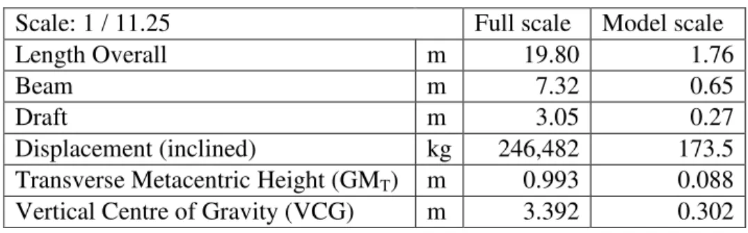
Table 1: Particulars of CCGA Miss Jacqueline IV
Scale: 1 / 11.25 Full scale Model scale
Length Overall m 19.80 1.76
Beam m 7.32 0.65
Draft m 3.05 0.27
Displacement (inclined) kg 246,482 173.5 Transverse Metacentric Height (GMT) m 0.993 0.088 Vertical Centre of Gravity (VCG) m 3.392 0.302
Model Paravanes
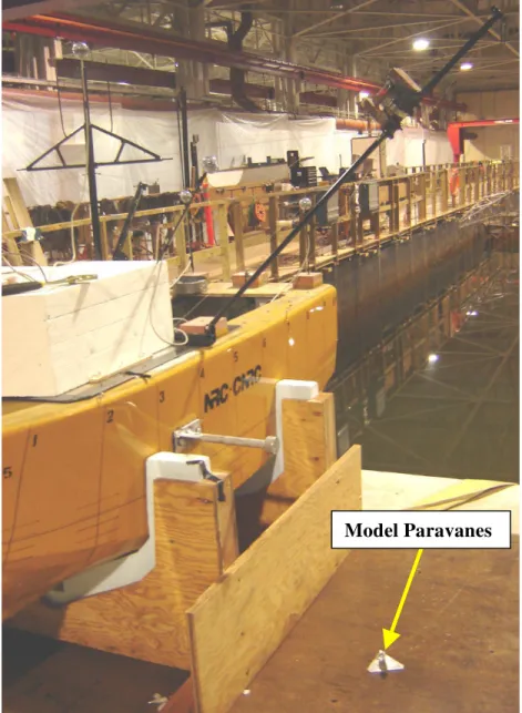
The ‘Miss Jacqueline IV’ is outfitted with paravanes. They are suspended from vertical hinged outriggers port and starboard, which are located directly behind the wheelhouse on the upper deck near amidships (Figure 5 and Figure 6). The paravanes were scaled using Froude scaling laws similar to the modeling strategy described in [12], [13]. The weight of the paravanes and their principle dimensions were matched appropriately. However, the thickness of the aluminiumplate sections used in the construction of these model paravanes wasthicker than the scaling law suggested to use conveniently
available. The towline used was a fishing line with minimal stretching.
During the seakeeping test at the wave basin, the test runs would start while the model is stationary in waves. If it was one of those tests with the paravanes deployed, then the model would start the test run with the paravanes already deployed to save on the run length.
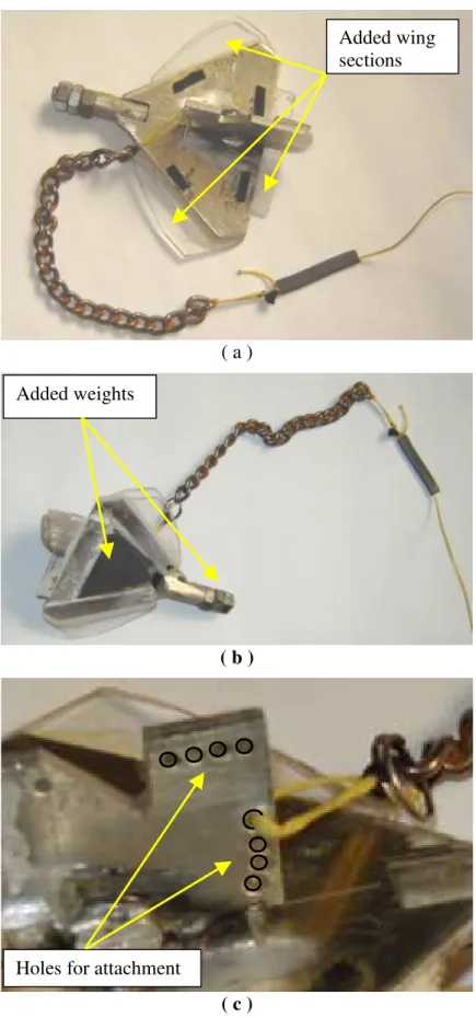
Before commencing the tests with paravanes in waves, calm water tests were performed at the corresponding model speeds to check whether the model paravanes would behave as expected, that is, stay submerged throughout runs and maintain a nominallyconstant orientation with respect to the calm water surface. It became immediately clear in the first attempt that the original model paravanes shown in Figure 6 (c) were not functioning properly. As the model hull accelerated, the paravanes would rise(similar to a plane taking off) and break the water surface. In order to addressthis problem, the hole that the towline was attached was shifted one by one on the top row of the holes shown in Figure 7 (c). The shifting the attachment point to any of the other holes did not cure the
planar rotation. In order to prevent this, a chain segment was introduced between the paravanes and the towline (Figure 7). The outcome was again unsatisfactory, thus additional weights were added to the bottom and the front tip in the form of a flat triangular section and nuts respectively (Figure 7 (b)) to counter balance the unbalanced hydrodynamic moments. As mentioned in [12], the equilibrium position of the paravane + towline system is important and depend on the forces exerted on the paravane (lift, drag and weight) in addition to the towing force. Hence, the design of paravane as well as the towline and the bridle system become important parameters. It is desirable that this equilibrium position be beneath the surface at a certain depth and remains this way. Otherwise, as observed in these tests, the paravanes would fail in two ways. Either they would steadily riseand break the water surface or the front tip would dip in, become vertical and break the surface. By the time they worked properly, four more holes on the side and three Plexiglass™ wing sections were added to the paravanes. With these additions, the model paravanes were probably heavier than the full-scale counterparts. The full scale paravanes had also some length of chain attached to them. Unfortunately, there was no way of scaling the weight of the towline + paravane system. Some design considerations for the future modeling of paravanes would be:
• The connection (bridle system) between the towline and paravanes is important. It should enable the paravanes to swivel about the connection point.
• In these model paravanes, though the principle dimensions and the total weight were scaled correctly, the mass distribution was not. However, the centre of mass is an important parameter together with the total weight in counter balancing the hydrodynamic moments.
Description of the Instrumentation
This section describes the instrumentation and calibration methodology used for each parameter measured:
Model Motions
Two independent systems were used in the experiment to measure the model motions – a MotionPak II and the QUALISYS system. As these systems are based on different principles, more confidence can be placed in the systems if they achieve similar results. Output from the MotionPak II was also verified against two linear accelerometers located at the bow of the model.
BEI Systron Donner Inertial Division MotionPak II: The MotionPak II is a solid state,
six degree of freedom, inertial sensing system used to measure angular rates and linear accelerations. Three orthogonally mounted GyroChip quartz rate gyroscopes are used to measure the three angular velocities; roll, pitch and yaw. Three orthogonally mounted silicon accelerometers measure the three linear accelerations; heave, sway and surge. Both the angular velocities and linear accelerations were manually calibrated. Angular velocities were calibrated relative to the output from a turntable that could be rotated at specified angular rates. Accelerations were calibrated in terms of g’s, where the
angles and the angle was measured with a digital inclinometer. The acceleration was computed using: A = 1*cos (angle).
Dedicated MotionPak II motions data analysis software was run to compute motions at the center of gravity in an earth fixed co-ordinate system. The following 18 channels were output: three orthogonal angular accelerations/rates/angles (roll, pitch and yaw) and three orthogonal linear accelerations/velocities/displacements (surge, sway and heave).
QUALISYS: Several infrared emitting bulbs were strategically placed on the model so
that the QUALISYS cameras could track its 3D position. The QUALISYS system is used to determine six motions: orthogonal linear displacements (X, Y, Z), which are translated to the model’s center of gravity, the heading angle, and the pitch and roll angle in a body co-ordinate system.
Bow Accelerometers: Two linear accelerometers were installed well forward of the
MotionPak II to measure lateral and vertical acceleration solely to provide verification of the MotionPak II analysis algorithm. The sensors were calibrated using the same
procedure as was used to calibrate the accelerometers in the MotionPak II.
Rudder Angle
Rudder angle was measured by installing a rotational potentiometer on the pivot point of the rudder. This parameter was calibrated relative to a protractor fitted adjacent to the linkage. No effort was made to duplicate the ship’s rudder slew rate model scale.
Shaft Rotation
The shaft rotation was measured using a tachometer integral with the propulsion motor. The tachometer provided an analog signal linearly proportional to shaft speed and was calibrated using a laser tachometer aimed at a piece of reflective tape on the shaft.
Wave Elevation
Wave elevation was measured using four capacitance wave probes located at different positions in the OEB. Wave matching was conducted using a separated wave probe nominally located at the OEB’s test center – an arbitrary central point in the OEB.
Data Acquisition
All analog data was low pass filtered at 10 Hz, amplified as required, and digitized at 50 Hz. All data acquired from the model was conditioned on the model before transfer to onshore data acquisition computer through radio telemetry. The wave and QUALISYS data were conditioned/digitized using a NEFF signal conditioner, transferred to the data acquisition system via cable and stored in parallel with the model data. Synchronization between the NEFF data and telemetry is nominally within 0.2 s.
A list of analyzedsignals measured is provided in Table 2. All signals were calibrated using the standard sign convention described in [14].
The OEB was configured to the following requirements:
Water Depth: The water depth was set at 2.8 meters for the seakeeping experiments. This allowed the assumption that the model was operating in deep water so there were no shallow water hydrodynamic effects.
Wave Generation: Several multi-directional irregular waves, corresponding to the waves as measured at sea during the full scale trial using two moored directional wave buoys, were matched with a dominant wave direction relative to the OEB south wall of 25 degrees and 65 degrees. Two wave directions were used to provide some flexibility regarding the model direction. The full scale wave repeat period was nominally 25 minutes in length.
Video Cameras
Three digital video (DV) cameras were used to record the test runs, all located at different positions:
Model Control System:
The model’s shaft speed and rudder angle were controlled using software installed on an on-shore desktop computer that communicated with the model via wireless modem. Model shaft speed settings were determined iteratively to achieve the desired calm water model and shaft speed remained constant throughout the run. No autopilot was fitted in model IOT745 due to weight constraints although all non-zero ship trial runs were executed using autopilot control. The rudder angle was manually controlled using a commercial video game steering wheel.
Table 2: List of Analyzed Signals
CHANNEL DESCRIPTION UNITS 1] North Center Wave Probe m 2] Shaft RPM RPM 3] Rudder Angle deg. 4] MP_Surge_Displacement m 5] MP_Surge_Acceleration m/s2 6] MP_Sway_Displacement m 7] MP_Sway_Acceleration m/s2 8] MP_Heave_Displacement m 9] MP_Heave_Acceleration m/s2 10] MP_Heading_Angle deg. 11] MP_Yaw_Velocity deg./s 12] MP_Pitch_Angle deg.
13] MP_Pitch_Velocity deg./s 14] MP_Roll_Angle deg. 15] MP_Roll_Velocity deg./s 16] Model Speed knots 17] QUALISYS Vertical Displacement m 18] QUALISYS Heading Angle deg. 19] QUALISYS Pitch Angle deg. 20] QUALISYS Roll Angle deg. NOTE: MP – MotionaPak II
A Note on the Numerical Prediction Program ‘MOTSIM’
In the results section of this paper, comparisons include three sets of results: from sea trials, model tests and numerical simulations using MOTSIM. MOTSIM is a non-linear time domain panel code that simulates six degrees of freedom motion [15]. The principle characteristics of this computational intensive software are:
- non-linear Froude-Krylov forces based on the calculated wetted surface of the hull at each time step; and
- radiation and diffraction forces are determined as a single set of scattering forces (based on relative motions) and obtained from memory functions, which are evaluated based on linear theory using a three dimensional panel code.
Over the last several years, MOTSIM has been validated against a number of full scale and model scale data sets, and improvements such as a manoeuvring prediction capability as well as a capability to predict Motion Induced Interruptions (MIIs) have been added.
Results and Discussions
From Figure 8 to Figure 15 are given the results for comparisons among the three sets of data: sea trials, model tests and numerical simulations using MOTSIM. A more
comprehensive correlation study for the three sets of data is given [16]. During the seakeeping trials, there were no direct measurements of the forces exerted by the paravanes. Therefore, in the succeeding comparisons, a successful physical/numerical model would generate similar motion responses as was measured during the sea trials. In the Figures 8 to 15, the following designations are used for the heading descriptions.
Figure 8 shows the comparison of the roll angles among the three sets: sea trials, model tests and the numerical simulations. Model tests with paravanes show a good match only bow and beam seas. For other headings the correlations are rather poor. MOTSIM simulations for this case also had similar results.
Heading Head Bow Beam Quartering Following Angle (deg) -105 -60 30 120 165
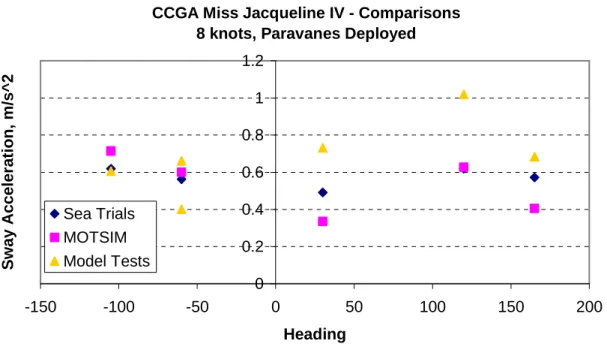
For pitch angle, bow, quartering and following seas had good correlations for model tests (Figure 9). MOTSIM results show much better correlations for yaw angles (Figure 10). For surge, sway and heave accelerations similar correlations to angular motions were obtained (Figures 11 to 13).
For Figures 14 and 15, the following headings are used:
Figure 14 presents the comparisons for roll, pitch and heave motions for sea trials only between no paravanes and with paravanes cases. The vessel speed was 8 knots. There is a clear reduction in roll motion when the paravanes were deployed. Pitch remained almost unchanged, as ideally would happen. Heave motion does not have a clear trend for this comparison.
In Figure 15, the same comparisons were performed for model seakeeping tests. The effects of paravanes seem to be a classic textbook response.
Overall, correlations for results with and without paravanes deployed as reported in [16] are rather on the poor side. There are various factors contributing to this and it cannot be solely attributed to the modeling of the paravanes.
Full Scale Data: For seakeeping, by far the most important issue with respect to the correlation is the integrity of the wave data. The variation of the wave field with time, the spatial variation of the wave field along with the actual measurement issues
associated with a moored directional wave buoy combine to provide a challenge in quantifying the environmental excitation. The fact that heave is significantly under predicted model scale and the peak roll amplitude is offset in terms of wave direction implies that the wave buoy mooring may have had an undesirable influence on the full scale directional wave data acquired.
The lack of an autopilot on model IOT745 is also assumed to be a significant correlation complication given the rather erratic steering noted.
Physical Model Data: For the seakeeping tests, emulating a real multi-directional wave field in the relatively small OEB is compromised by the inevitable spatial variation in the field combined with beach reflection induced anomalies. Dedicated research is required to address these issues and collaboration with other wave basins facing similar challenges is recommended.
The other major limitation related to carrying out seakeeping experiments in the OEB is the relatively short run lengths and small model scale. Ongoing efforts are underway to devise test strategies to mitigate the negative aspects of the small basin size.
Heading Head Bow Beam Quartering Following
The poor description of the full scale ship geometry and the difficulty duplication the full scale hydrostatics model scale was also a significant source of error.
Conclusions
In the preceding, model seakeeping tests and corresponding results were presented for a fishing vessel model with paravanes. Difficulties encountered in modeling the paravanes are presented. Some of the points that should be noted in modeling the paravanes are:
• In these model paravanes, though the principle dimensions and the total weight were scaled correctly, the mass distribution was not. However, the centre of mass is an important parameter together with the total weight in counter balancing the hydrodynamic moments.
• The connection (bridle system) between the towline and paravanes is important. It should enable the paravanes to swivel about the connection point.
Acknowledgements
This project is collaborative project between SAFETYNET, Memorial University of Newfoundland, National Research Council of Canada – Institute for Ocean Technology, and Canadian Coast Guard. The authors would like to thank the crew of the all the fishing vessels used in the sea trials, for their enthusiastic and professional support, the CCG for the loan of survival equipment and permission to use their berth facility at the Coast Guard Base (St. John’s), Jack Foley of MUN Oceanography for assistance designing the wave buoy mooring and deploying the wave buoy, Mr. Reg Fitzgerald of Oceans Ltd. for their wave buoy support and IOT technical staff for their efforts throughout the planning and execution of the trial. Support from Oceanic Consulting Corporation for transport support and the Offshore Safety and Survival Centre (OSSC) for Marine Emergency Duty (MED) survival training for IOT staff was much appreciated. Funding support from the Search & Rescue (SAR) New Initiatives Fund (NIF) and the Canadian Institutes of Health and Research (CIHR) is gratefully acknowledged.
References
[1] “SafetyNet – a Community Research Alliance on Health and Safety in Marine and Coastal Work”, www.SafetyNet.MUN.ca, February 2007.
[2] Cumming, D., Fleming, T.,”Description of Seakeeping Trial Carried Out on CCGA Miss Jacqueline IV– October 2004”, IOT Trials Report TR-2004-15, December 2004.
[3] Barrett, J, Cumming, D., Hopkins, D.,”Description of Seakeeping Trials Carried Out on CCGA Atlantic Swell – October 2003”, IOT Trials Report #TR-2003-28, December 2003.
[4] Cumming, D., Hopkins, D., Barrett, J.,”Description of Seakeeping Trial Carried Out on CCGS Shamook – December 2003”, IOT Trials Report #TR-2004-01, January 2004.
[5] Fleming, T., Cumming, D.,”Description of Seakeeping Trial Carried Out on CCGA Nautical Twilight – November 1, 2004”, IOT Trials Report TR-2004-13, December 2004.
[6] Cumming, D., Fleming, T.,”Description of Seakeeping Trial Carried Out on CCGA Roberts Sisters II – November 2004”, IOT Trials Report TR-2005-09, July 2005.
[7] Stevens, S.C., Parsons, M.G., “Effects of Motion at Sea on Crew Performance: A Survey”, SNAME Publication Marine Technology, Vol. 39, No. 1, January 2002, pp. 29 – 47.
[8] Boccadamo, G., Cassella, P., Scamardella, A., “Stability, Operability and
Working Conditions Onboard Fishing Vessels”, 7th International Conference on Stability of Ships and Ocean Vehicles, Launceston, Tasmania, Australia,
February 7-11, 2000.
[9] Crossland, P., Rich, K.J.N.C., “A Method for Deriving MII Criteria”,
Conference on Human Factors in Ship Design and Operation, London, U.K., September 27 – 29, 2000.
[10] Graham, R., “Motion-Induced Interruptions as Ship Operability Criteria”, Naval Engineers Journal, March 1990.
[11] Institute for Ocean Technology Standard Test Method: “Construction of Models of Ships, Offshore Structures and Propellers”, V9.0, 42-8595-S/GM-1, October 28, 2004.
[12] Dodge, R. A., Smith, H. J. and Sonneman, G. “A Study and Development of Paravanes of the High Lift-Drag Ratio Type and the High-Lift Type.” Technical Report, Engineering Research Institute, the University of Michigan Ann
Arbour, July 1955.
[13] Goudey, C. A. and Venugopal, M. “Roll Damping on Two New England Trawlers: An Experimental Study”, Marine Technology, Vol 26, No 2, April 1989, pp 160-167.
[14] Institute for Ocean Technology Standard Test Method: “Model Test Co-
ordinate System & Units of Measure”, V6.0, 42-8595-S/GM-5, November 29, 2004.
[15] Pawlowski, J.S., and Bass, D.W.,”A Theoretical and Numerical Study of Ship Motions in Heavy Seas”, Transactions SNAME, New York, October 1991. [16] Akinturk, A., Cumming, D., Bass, D., Walsh, A.,” Description Of Seakeeping
Experiments Carried Out On CCGA Miss Jacqueline IV Model IOT745”, IOT Test Report TR-2007-06, 2007.
Figure 1 Offshore Engineering Basin (OEB) layout Oblique
Waves
Wave Generation: All waves were generated obliquely with no Blanking Plates Installed.
Monitoring Wave
Figure 3: Fully outfitted Model IOT745 in OEB (Paravanes Deployed)
Figure 4: Model IOT745 Propeller/Rudder Arrangement
Paravane Outrigger w/Ballast Weight
Figure 5: Model Paravanes
( a )
( b ) full scale ( c ) model scale
Figure 6: Miss Jacqueline IV Paravanes
PARAVANE OUTRIGGERS – PORT AND STBD.
( a )
( b )
( c )
Figure 7: Modifications to the model paravanes Added wing sections
Added weights
CCGA Miss Jacqueline IV - Comparisons 8 knots, Paravanes Deployed
0 2 4 6 8 10 -150 -100 -50 0 50 100 150 200 Heading R o ll A n g le , d e g re e s Sea Trials MOTSIM Model Tests
Figure 8 Comparisons - roll angle with paravanes deployed
CCGA Miss Jacqueline IV - Comparisons 8 knots, Paravanes Deployed
0 1 2 3 4 5 6 -150 -100 -50 0 50 100 150 200 Heading P it c h A n g le , d e g re e s Sea Trials MOTSIM Model Tests
CCGA Miss Jacqueline IV - Comparisons 8 knots, Paravanes Deployed
0 2 4 6 8 10 12 -150 -100 -50 0 50 100 150 200 Heading Y a w A n g le , d e g re e s Sea Trials MOTSIM Model Tests
Figure 10: Comparisons - yaw angle with paravanes deployed
CCGA Miss Jacqueline IV - Comparisons 8 knots, Paravanes Deployed
0 0.1 0.2 0.3 0.4 0.5 0.6 -150 -100 -50 0 50 100 150 200 Heading S u rg e A c c e le ra ti o n , m /s ^ 2 Sea Trials MOTSIM Model Tests
CCGA Miss Jacqueline IV - Comparisons 8 knots, Paravanes Deployed
0 0.2 0.4 0.6 0.8 1 1.2 -150 -100 -50 0 50 100 150 200 Heading S w a y A c c e le ra ti o n , m /s ^ 2 Sea Trials MOTSIM Model Tests
Figure 12: Comparisons - sway acceleration with paravanes deployed
CCGA Miss Jacqueline IV - Comparisons 8 knots, Paravanes Deployed
0 0.5 1 1.5 2 2.5 -150 -100 -50 0 50 100 150 200 Heading H e a v e A c c e le ra ti o n , m /s ^ 2 Sea Trials MOTSIM Model Tests
CCGA Miss Jacqueline IV - Comparisons for 8 knots No Paravanes vs Paravanes Deployed
0 2 4 6 8 10 12 0 45 90 135 180 Heading A c c e le ra ti o n ( m /s ^ 2 ) 0 0.5 1 1.5 2 2.5
Roll (no para) Roll (w/para)
Pitch (no para) Pitch (w/para)
Heave Accel. (no para) Heave Accel.(w/para)
A n g le ( d e g )
Basic Seakeeping Results (8 knots) 0 1 2 3 4 5 6 7 0 45 90 135 180
Heading Angle (deg.)
A n g le ( d e g .) 0 0.2 0.4 0.6 0.8 1 1.2 A c c e le ra ti o n ( m /s ^ 2 )
Roll (no para) Pitch (no para) Roll (w/para) Pitch (w/para)
Heave (no para) Heave (w/para)
Figure 15: Effects of paravanes on motions (MODEL SCALE)
CCGA Miss Jacqueline IV - Comparisons for 8 knots No Paravanes vs Paravanes Deployed