Analysis and Optimization of the Graz Cycle: A Coal Fired Power Generation Scheme with Near-Zero Carbon Dioxide Emissions
by
Brentan R. Alexander
SUBMITTED TO THE DEPARTMENT OF MECHANICAL ENGINEERING IN PARTIAL FULFILLMENT OF THE REQUIREMENTS FOR THE DEGREE OF
BACHELOR OF SCIENCE AT THE
MASSACHUSETTS INSTITUTE OF TECHNOLOGY
JUNE 2007
©2007 Brentan R. Alexander. All rights reserved. The author hereby grants to MIT permission to reproduce
and to distribute publicly paper and electronic copies of this thesis document in whole or in part
in any medium now known or hereafter created.
Signature of Author:_______________________________________________________ Department of Mechanical Engineering
May 11, 2007 Certified by:_____________________________________________________________
Ahmed F. Ghoniem Professor of Mechanical Engineering
Thesis Supervisor Accepted by:_____________________________________________________________
John H. Lienhard V Professor of Mechanical Engineering Chairman, Undergraduate Thesis Committee
2
Analysis and Optimization of the Graz Cycle: A Coal Fired Power Generation Scheme with Near-Zero Carbon Dioxide Emissions
By
Brentan R. Alexander
Submitted to the Department of Mechanical Engineering On May 11, 2007 in partial fulfillment of the Requirements for the Degree of Bachelor of Science in
Mechanical Engineering
Abstract
Humans are releasing record amounts of carbon dioxide into the atmosphere through the combustion of fossil fuels in power generation plants. With mounting evidence that this carbon dioxide is a leading cause of global warming and with energy demand exploding, it is time to seek out realistic power production methods that do not pollute the environment with CO2 waste. The relative abundance and low cost of fossil fuels remains attractive and clean coal technologies are examined as a viable solution.
This paper helps identify the many options currently available, including post-combustion capture, pre-post-combustion capture, and a number of oxy-fuel post-combustion schemes. One cycle design in particular, the Graz cycle, holds some promise as a future power generation cycle.
A model of the Graz cycle developed in this paper predicts a cycle efficiency value of 56.72%, a value that does not account for efficiency losses in the liquefaction and sequestration of carbon dioxide, or the efficiency penalty associated with the gasification of coal. This high efficiency number, coupled with the low technological barriers of this cycle compared to similar schemes, is used as a justification for investigating this cycle further.
A sensitivity analysis is performed in order to identify key system parameters. Using this information, a computational optimization algorithm based on a simulated annealing scheme is devised and used to alter the parameters until an overall efficiency of 60.11% is achieved. Another optimization scheme which accounts for hardware limitations and plant capital costs is also discussed. This optimization yields a total efficiency of 58.76% while limiting the system high pressure to 110 bar.
With such high efficiency values for this cycle, it is suggested that further study with more advanced models be conducted to better assess the viability of the Graz cycle as a clean technology.
Thesis Supervisor: Ahmed F. Ghoniem Title: Professor of Mechanical Engineering
3
Contents
Abstract ... 2
Contents ... 3
Global Warming: The Carbon Dioxide Problem ... 4
Coal as a Fuel Source ... 7
Fossil Fuels: A Necessary Evil ... 7
Choosing Coal ... 8
Gasification ... 11
Fixed Bed Gasification ... 12
Fluidized Bed Gasification ... 13
Entrained Flow Gasification ... 13
The Advantages of Gasification ... 14
Carbon Capture Technologies ... 15
Post-Combustion Technology ... 16
Pre-Combustion Technology ... 19
Oxy-Fuel Combustion Technology ... 23
The Oxy-Fuel Combined Cycle and the CC-Matiant Cycle ... 24
The Water Cycle ... 28
The Matiant Cycle ... 29
The E-Matiant Cycle ... 31
The Graz Cycle ... 33
A Comprehensive Study of the Graz Cycle ... 34
The choice of the Graz cycle ... 34
Building a Cycle Model ... 37
Sensitivity Analysis ... 53
Sensitivity of System State Parameters ... 53
Sensitivity of Component Efficiencies ... 60
Optimizing the Graz Cycle ... 64
Difficulties of Optimization ... 64
The Modified Simulated Annealing Algorithm ... 65
Optimization Results ... 69
An Alternative Cost Function ... 80
Future Work ... 89
4
Global Warming: The Carbon Dioxide Problem
The Industrial Age ushered mankind into a new and exciting world of mechanical automation and assistance that brought about manufacturing efficiency never before seen. Society, long accustomed to nominal energy consumption through wood stoves, sought to find new sources of energy to power these new machines that promised wealth and comforts for more people. Fossil fuels began to be consumed in large quantities to satiate the exploding demands for energy across the globe.
Over a century and a half later, the ramifications of this widespread and ever growing use of fossil fuels is beginning to be understood. The by-products of the combustion processes used to extract energy from fuels such as coal, oil, and natural gas, are substances that can be dangerous and have unintended effects when released en masse into the earth’s atmosphere. Besides NOx and SOx, which are potent poisons that can cause serious health issues in short periods of time to those exposed, carbon dioxide is increasingly becoming a danger to the earth and those that inhabit it.
The earth’s atmosphere is a complex and delicate blanket necessary for life. Without this layer, the earth would lose a majority of the energy that impacts it, leaving the average surface temperature at -19°C, a far cry from the comfortable average of 15°C the earth feels now. (1) The atmosphere keeps the earth warm, and this
phenomenon, known as the greenhouse effect, is one of the most important functions of the atmosphere, which despite consisting mostly of nitrogen and oxygen, has the carbon dioxide in its upper reaches to thank for this effect. Radiation from the sun hitting the earth has a wavelength of between 0.4 and 0.7 μm. (1) When reflected back from the earth’s surface, the emanating radiation wavelength is larger, at 4-100 μm. (1) Carbon dioxide, which absorbs energy in the 13-19 μm range, traps some of this
reflected energy in the atmosphere and as a result the surface temperature rises. (1) Carbon dioxide is dangerous as a pollutant because its increased concentration in the atmosphere will trap more energy in the earth’s atmosphere, leading to a rise in the global mean temperature. Figure 1 shows data revealing the steady increase in
5
global atmospheric CO2 concentrations as measured in Hawaii and the overall rise in the global mean temperature during the same timeframe: (2)
Figure 1: The correlation between the yearly atmospheric CO2 concentration at
Mauna Lao, Hawaii, and the annual global mean temperature is shown (2)
It has been argued by some that the increase in mean temperature over this time could have been caused by natural variations in the earth’s climate that have occurred
periodically over the millennia, however the change in temperature has been so fast and drastic that it can only fully be explained by the rapid increase in carbon dioxide
concentration in the atmosphere, which had remained relatively constant at 280 ppmv until the early 1800s and the dawn of the Industrial Revolution. (1) When a larger time-scale is observed, going back hundreds of thousands of years, it becomes evident that atmospheric carbon dioxide concentrations do naturally fluctuate over time.
Comparison to modern concentration levels, however, show that the current levels of CO2 in the atmosphere are higher than at any point in history. Even if a portion of the increase in carbon dioxide concentrations is natural, human interaction is only speeding the process, and the ramifications of the extra CO2 may prove disastrous.
6
A rise, even very slight, in the earth’s mean temperature would have far reaching effects on the planet and its ecosystems. If energy usage and CO2 concentrations
continue to grow at the current rates shown in Figure 2, the average terrestrial temperature will increase 0.3°C every decade. (4)
Figure 2: CO2 emissions by fuel source, 1970-2025 (estimated) (3)
One important ramification of this increased mean temperature is a rise in ocean levels. As the temperature rises, polar ice will begin to melt and return to the oceans, resulting in an average six centimeter rise in the ocean levels per decade if energy usage trends continue. (4) Such a rise in ocean levels would be devastating to low-lying coastal communities like those found in Egypt, Southeast Asia, and the Caribbean. This rise in temperature would also trigger droughts leading to food shortages in areas of the globe already vulnerable to famine, like desert regions in North Africa and South America. (4) As vegetation changes in regions due to the climate change, animal populations will also have to move with their food sources. This movement of large plant and animal
populations could weaken ecosystems and have particularly damaging effects on
systems already facing extinction. (4) Even disease can spread to new populations as the animal species that carry them move to different latitudes in response to climate
changes. Some scientists suggest that more severe weather systems will result from warmer oceans caused by the increased greenhouse effect. (4)
300 5300 10300 15300 20300 25300 30300 35300 40300 45300 1970 1980 1990 2000 2010 2020 C O2 Pr o d u ce d ( m illi o n s o f m e tr ic t o n s)
7
No one is certain of the extent to which global warming will cause devastation. What is certain is that an unabated rise in terrestrial carbon dioxide concentration will lead to an unwanted outcome, which even in the best-case scenario is far too
destructive to ignore.
Coal as a Fuel Source
Fossil Fuels: A Necessary Evil
With global warming causing increased concern and leading to possible taxes on what power plants and chemical plants spew into the atmosphere, it seems
counterproductive and misguided to place resources into fossil fuels, let alone coal, as the fuel of choice for the future. Indeed, fossil fuel fired power plants are the chief source of carbon dioxide emissions worldwide, and coal plants around the world are among the worst pollution offenders, often pouring tons of carbon dioxide, sulfur oxides, and other toxic gases into the air.
Fossil fuels, however, are a necessary evil. Figure 3 shows projected energy demand, broken down by economy type:
8
Energy demand is growing steadily worldwide, and as more emerging economies, like China and India, begin and continue to modernize, their energy demands will increase as well. Indeed, in the 20 year period between the year 2000 and 2020, energy demand worldwide is expected to grow by more than 50%.
Where will all this energy come from? Figure 4 shows the breakdown in energy production by type in 2006:
Figure 4: 2006 Energy consumption by fuel type (5)
The fossil fuel family accounted for 85% of all energy produced worldwide. Even with new renewable energy technologies and increasing interest in nuclear energy, the higher costs of renewable energy and nuclear energy make them undesirable
economically as a fuel source. (5) As a result, it is clear that fossil fuels will remain the dominant fuel source worldwide for energy production.
Choosing Coal
Despite a continued use of fossil fuels, the choice to use coal as a primary fuel source still seems odd. Coal has been a traditionally dirty technology, often associated with acid rain and other environmental disasters. Natural gas, or methane, on the other hand, burns very cleanly through the following equation:
CH4 + 2O2 → CO2 + 2H2O Coal 23% Natural Gas 22% Petroleum 40% Nuclear 8% Renewables 7%
9
It seems that natural gas would be the correct choice for the fuel to make carbon dioxide capture and removal as cheap and easy as possible. Even oil, when properly refined and burned, is cleaner than coal and requires less toxin removal to make it a truly clean technology. If it is necessary to pay to remove carbon dioxide from the exhaust of a fossil fuel plant, why would it be desirable to still pay further to remove other pollutants trapped within coal?
The realities of supply limitations and the complexities of the global economy help to explain the attractiveness of coal. Figure 5 shows the prices of both natural gas and oil over the last 35 years:
Figure 5: Natural gas and oil prices over time (6) (7)
Since the late 1990s, the prices of both fuels have more than tripled. The reasons behind this spike in prices are complex. One important factor has been the increased demand of both fuel types. For oil, worldwide demand has increased significantly in the last decade and is projected to grow further (see Figure 5). Natural gas suffers a similar demand problem; high efficiency natural gas combined cycle power plants were the choice for new construction in the United States throughout the 1990s, and as more of these plants came online, demand for fuel spiked. (6)
10
This surge in demand, however, is not the only factor behind the rise in prices. Another equally important factor is the depletion of resources within the United States. Natural gas reserves in the United States in particular have dwindled in the last ten years, and as a result there is an increased dependency on imported gas. (6) Europe has a similar problem, with little reserves of its own. With a volatile political situation in the Middle East, the largest oil producing sector in the world, added to this equation of dwindling domestic supply, the supply of oil and natural gas becomes unstable and unreliable. As a result, prices fluctuate wildly and foreign control artificially raises prices.
The price of coal, however, has remained fairly flat over the last half-century, as exhibited in Figure 6:
Figure 6: Price of different coal types over time (8)
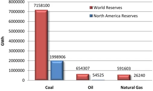
This shows coal to be a cheap and stable fuel with respect to both oil and natural gas. The prospects for the growth of coal as a fuel source are encouraging as well. Figure 7 shows a 2006 EIA estimation of remaining coal, oil, and methane reserves both worldwide and in the United States:
11
Figure 7: 2006 estimated recoverable resources by fuel type (8)
The study shows coal as a clear winner. Worldwide, there is over ten times the energy available through coal reserves as oil reserves. The types of supply shortages currently seen in the oil industry would not be an issue with coal for hundreds of years.
Domestically, coal has an advantage as well. In North America, the estimated coal reserves are larger than the sum of the worldwide estimated oil and natural gas reserves. In addition, the North American coal reserves are estimated to be 36 times larger than the North American oil reserves, and over 76 times larger than the natural gas reserves. (8) This fact means coal can be produced locally near the point of power production, eliminating the supply uncertainties that currently drive the oil market.
All this together means that coal can provide a cheap, stable, domestic fuel supply for centuries, making it an economically clear choice between the fuels. But the problems associated with coal as a dirty fuel source remain, and technologies to address this fact and produce clean burning coal to ease carbon capture are required.
Gasification
The most important component in clean coal technology is the gasifier. Gasification is a relatively old technology that oxidizes a fuel in an oxygen deprived environment. This environment does not allow enough oxygen for full combustion to
7158100 654307 591603 1998906 54525 26240 0 1000000 2000000 3000000 4000000 5000000 6000000 7000000 8000000
Coal Oil Natural Gas
GW
h
World Reserves
12
occur, and as a result a syngas is produced which can be used as a fuel source later. In general, gasifiers convert fuel using the following reaction:
The product synthesis gas, or syngas, that is made up of carbon monoxide and
hydrogen, can then be used as a fuel. In practice, the synthesis gas also contains carbon dioxide, sulfur dioxide, methane, and other trace components.
Gasification takes place in three major stages: drying, devolatilization, and gasification. During the drying stage, the input fuel, or feedstock, is heated to over 100°C, at which point the water content in the fuel vaporizes and leaves. During the devolatilization stage, the feedstock is heated to between 500°C and 900°C, where the bonds between volatiles and char structure rupture. The products of this process are tars, hydrocarbon based liquids, hydrocarbon based gases, carbon dioxide, carbon monoxide, hydrogen, and water. These products are then further heated and
pressurized. At these high temperatures and pressures, some of the products will fully combust to provide thermal energy for the other stages. The majority of the products will, however, gasify, leaving an output stream of syngas. The unusable remnants of this process, known as slag, are removed as a liquid or a solid from the gasification chamber and disposed.
Gasifiers all fall into one of three categories, depending upon the way in which they perform their gasification: Fixed bed, fluidized bed, and entrained flow gasifiers.
Fixed Bed Gasification
Fixed bed gasifiers make use of a system of grates, spaced throughout the gasifier vessel. As large chunks of feedstock are fed into the top of the unit, they fall upon the grates and begin the gasification process. As the pieces of feedstock lose mass and become smaller, they are able to fall through the grate to the next grate below. As the particle falls, the holes in the grate become smaller and smaller.
13
In these systems, drying occurs first at the top of the vessel, with devolatlization occurring next as the particle falls. Gasification occurs in the zones at the bottom of the vessel, producing the thermal energy to heat the feedstock in the stages above.
This type of gasifier has been used successfully for many years in South Africa, and is known as the Lurgi fixed bed gasifier. Despite this success, however, interest in fixed bed gasifiers has waned due to their inability to handle caking and low quality coals and their high residence times for particles in the vessel.
Fluidized Bed Gasification
Fluidized bed gasifiers use technology similar to fluidized bed combustors. In these systems, fine coal particles are fed into a highly turbulent environment and mixed with oxygen and water. The coal particles remain suspended within the fluidized bed as slag components fall to the bottom of the vessel and gasification products flow to the top and out.
These systems have the advantage of fast residence times on the order of a few seconds, as well as the ability to accept a wide range of feedstocks, including coals of various quality, wood, and solid waste. Unfortunately, the exhaust stream from the vessel is rich in char, meaning full gasification does not take place within the vessel. As a result, the exhaust gases must be extensively recycled to the gasifier in order to reach a satisfactory conversion efficiency, which increases the energy requirements of the system.
Entrained Flow Gasification
Entrained flow gasifiers represent the current state of the art technology, and it is in these designs that the most interest today is paid. Entrained flow gasifiers, like the other gasifiers, come in many versions and flavors. All these devices work in a similar fashion. One design, produced by Texaco, is shown in Figure 8.
In these gasifiers, a coal slurry or a stream of finely ground coal is passed into the gasification chamber. Drying, devolatilization, and gasification all occur very quickly as the entrained flow moves down the body of the gasifier. The largest portion of the
14
gasifier body is used for cooling the syngas exiting the gasifier. This cooling raises steam that can be used in a bottoming cycle,
while also cooling the syngas to allow slags and other undesirable components to fall out of the flow. Other designs employ a quench cooling scheme, where the syngas is passed through a water bath to cool and remove slags. (9)
These entrained flow gasifiers have the desirable ability to be able to gasify any coal, regardless of its caking characteristics or rank. It also features very short residence times and uniform temperatures. The problems with these gasifiers involve the need to finely grind the feedstock before injection as well as
higher oxidant requirements than the other designs. Despite these shortcomings, the
entrained flow gasifier is now the gasifier
of choice, with most new installations that use gasifiers employing entrained flow designs.
The Advantages of Gasification
There are many barriers to the wide adoption of gasification technology. System cost is a large issue. Gasifiers large enough to serve a few hundred megawatt power plant are massive in scale, often ten or more stories tall. The construction of a vessel able to contain pressures of 40 bar on such a scale are expensive. Few have been built on this large scale and the overall operation of the gasifiers is still not well understood, leaving the door open for possible refinements and improvements to the system.
15
Reliability is also an issue for these plants, since gasifiers need to be shut down more often than the normal down time for a conventional plant. Most of the proposed designs also employ an air separation unit to provide the oxygen for the gasification process and as a result, significant power must be used from the plant to power the air separation unit. Another pitfall of gasifiers is their poor response times, meaning plants using these units cannot be used for load following.
Despite these issues, gasification provides many distinct advantages over a conventional coal burner. One is the ability to burn virtually any coal, as well as other feedstocks such as solid fuels and wood. This is a significant advantage as current coal power plants are often designed for a specific coal grade. The gasification process also removes corrosive ash elements that are often found in coal, including chloride and potassium compounds, which would normally corrode the insides of components used in a traditional coal plant.
The most obvious advantage of gasification, however, is the high quality syngas that is produced by the process. This syngas can be used in a conventional combined cycle plant, which affords overall plant efficiencies greater than what can be achieved in a traditional coal plant. Gasification is also particularly well suited for carbon capture since the synthesis gas that is produced, once removed of sulfur, is nearly as clean as methane, which means carbon capture can be performed with the smallest penalty possible.
Carbon Capture Technologies
There are many power cycles and plant layouts that have been proposed to capture the carbon dioxide emissions that a normal power plant produces. All of the schemes work independent of fuel source, and many have been developed with natural gas firing in mind. All of these cycles can be used to remove carbon emissions in a clean coal power plant utilizing a gasifier.
These schemes all fall into three general categories defined by the point in the cycle that carbon dioxide is removed, as well as the way in which the fuel is combusted
16
in the cycle: pre-combustion, post-combustion, and oxy-combustion. Each cycle type has distinct advantages and disadvantages associated with their implementation. A general introduction to the workings of each type of cycle, as well as some proposed designs within each cycle category, is presented here to help determine the power generation designs with the most promise.
Post-Combustion Technology
Post-combustion cycles utilize current power plant designs and proven
technologies with an added carbon dioxide stripping plant added to the exhaust stream of the power plant. Figure 9 shows how this technology can simply be added to the exhaust of any power cycle:
Figure 9: A post-combustion power cycle
There have been many proposals to perform the carbon dioxide stripping. One interesting possible solution involves the use of specialized membranes to separate carbon dioxide from the flue gas. At this time, however, membranes that can perform this task on an economically viable level are not available, and due to the similar size of the atoms in the exhaust gas, the production of a usable membrane that could perform better than currently available systems that employ other methods is unlikely. (10) It has been proposed that a Rectisol cycle, which uses methanol as a solvent to absorb carbon dioxide, be used, as is done for feed gas streams. This process seems ill suited for this application since it is a physical stripping method using a pressure swing. Due to the low concentration of carbon dioxide in the exhaust streams of power plants, physical
17
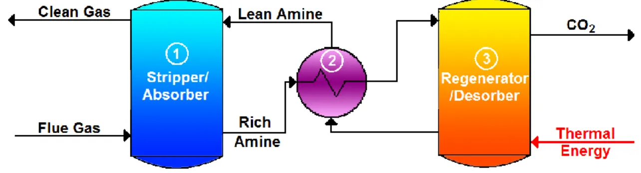
stripping means are impractical, which leaves only chemical stripping with temperature swing absorption. These stripper systems use an amine based solution to chemically bond with the carbon dioxide in the flue gas and pull it out of the exhaust stream. Multiple amines and mixtures of amines have been studied to determine the optimum solution mix, although the amine monoethanolamine (MEA) is most often employed. Figure 10 shows a typical amine plant setup, with the flue gas coming from a traditional power cycle:
Figure 10: An amine based carbon dioxide stripper
The amine reacts with the carbon dioxide in the exhaust stream within an absorber unit to form a carbonate ion that is dissolved in the water based solution by the following exothermic chemical reaction (1):
2MEA + CO2 ⇌ MEAH+ + MEACOO- (11)
The carbon-dioxide-rich amine solution is then heated in a heat exchanger (2) and passed into a regenerator (3) where input heat is used to reverse the above equation and regenerate the amine solution for use once more. This lean amine solution is then passed back trough the heat exchanger (2) and into the absorber.
In a study on the efficiency penalties associated with using amine stripping techniques for post-combustion carbon removal, Desideri and Paolucci note an
efficiency penalty of 11.6 percentage points when including carbon dioxide liquefaction on a coal fired plant. (11) Bolland and Undrum, in a similar analysis, find a final plant
18
efficiency of 49.6%, representing an 8.4 percentage point penalty. (12) It should be noted that the Bolland study assumes a natural gas fired plant, and Desideri and Paolucci note that a methane fired plant would see efficiency pentalties 3-4 percentage points lower than those for coal based plants. (11) This extra efficiency drop is due to gas cleanup which must be performed on coal flue gases to remove sulfur components before carbon dioxide stripping can be performed. This must be included because the amine solutions are very susceptible to poisoning, and sulfur in the exhaust stream will react with the amine and block its regeneration. These studies together place the total efficiency hit for post-combustion plants in the 11 percentage point range for coal.
The single largest advantage of the post-combustion technologies is their current availability as ‘off the shelf’ components. The power cycles, with only minor
modifications, can be used in their current designs. The amine stripping units are also commercially available now for immediate construction, (11) although Bolland et al note that the technology has not been sufficiently proven for large scale applications. (12)
Despite its immediate availability, this technology is in no ways a ‘slam dunk’ answer to the carbon removal problem. The high heat requirements for the amine regeneration, which are higher still for MEA based amines, represents a large and non-trivial loss to the overall energy output of the plant. Simply adding this unit to all current power cycles would reduce their total energy output by approximately 30%, requiring the construction of more plants and drastically increasing the price of electricity. The amine separation equipment also involves a large capital cost, and estimates place the price of electricity after such an upgrade at more than double its current price. (11) Another problem lies in the efficiency of the separation process itself, as it is only capable of removing at most 90% of the carbon dioxide from the plant exhaust. Extra care must also be taken with respect to the amine solution used, as the amines in the separator are corrosive and reactive, requiring a dilute solution to avoid damage to internal piping. And as noted previously, the amines also require gas cleanup before the stripper to remove SOx and NOx emissions (or the more expensive solution of
19
simple amine solution replacement), as these other pollutants bind with the amine and prevent its regeneration. (11)
Pre-Combustion Technology
Cycles in the pre-combustion category involve designs that remove the carbon atoms from the fuel source as carbon dioxide before the fuel is combusted in the presence of oxygen in a burner. Figure 11 shows the typical layout for a pre-combustion carbon removal power plant:
Figure 11: A Coal fired pre-combustion capture power cycle
These plants employ methane reformers or gasifiers (1) to produce a stream of syngas, composed of carbon dioxide, carbon monoxide, and hydrogen (2). This stream is cleaned (3) and mixed with water and passed through a shift reactor which turns the carbon monoxide and water in the stream into carbon dioxide and hydrogen (4). In this way, it operates similarly to current IGCC power cycle designs. Before this final mixture of carbon dioxide and hydrogen is passed into a burner, however, a separator is
employed. The nearly pure hydrogen stream is burned in a normal combined cycle plant (5) while the carbon dioxide is passed to a plant for liquefaction and storage (6).
The water-gas shift reactor works via the following chemical equation:
20
This reaction is exothermic and results in ∆rH=-41.16 kJ/Mol. This reaction requires
temperatures in excess of 900°C in order for the pace of the reaction to be sufficiently fast. (10) They also require excess water to be included in the reactor vessel to ensure full CO conversion. In practice, reactors typically use multiple stages at different temperatures to reduce size and energy utilization while increasing conversion efficiency. These reactors, known as the ‘Catalytic clean gas CO shift conversion’, can produce over 99% maximum CO conversion in two stages: high temperature conversion and low temperature conversion.
High temperature CO shift conversion works in operating temperatures between 300°C and 530°C. (10) Using Ni/Cr-oxide or Fe/Cr-oxide as the reaction catalyst, these reactors have an advantage of rapid conversion with a minimal size but suffer from incomplete conversion.
Low temperature CO shift conversion operates with temperatures between 180°C to 270°C and employ a Cu/Zn-oxide based catalyst. This reactor operates slower and with a larger volume; its chief purpose is to fully convert the remaining CO which passed through the high temperature stage.
These reactors are a middle-aged technology usually employed to turn methane into hydrogen fuel. They suffer, however, from a sensitivity to impurities, and as a result sulfur cleanup must be employed prior to this stage for plants fired by coal. The gas cleanup employed most often today is known as ‘Wet Scrubbing’ and is a physical separation scheme using a pressure swing. The process involves mixing the sulfur-rich syngas, known as a ‘sour’ syngas, with an alkaline based slurry in a turbulent
environment. The most common slurry uses limestone (CaCO3). Its interaction with sour gas produces the following reaction:
CaCO3 (s) + SO2 (g) → CaSO3 (s) + CO2 (g)
In this way, the sulfur is removed from the stream as a solid (calcium sulphite). The sulfur rich slurry is then passed to a regeneration unit where a pressure swing liberates
21
the sulfur, where it is removed as a solid. The treated syngas, now known as a ‘sweet’ sygnas, is passed on to the shift reactor. In practice, these systems can reach sulfer removal efficiencies of greater than 90%. (10) These systems are also a middle-aged technology, having been heavily developed in the late 1960s and early 1970s to combat a growing acid rain problem.
This gas cleanup presents a problem, however, because it must be done at low temperatures. As the temperature of the gas inside the scrubber increases, sulfur dioxide oxidizes further to form sulfur trioxide, which cannot be removed by a lime-based slurry. This fact requires the hot sour syngas leaving the gasifier to be cooled substantially before entering the desulfurization unit. The gas must then be reheated after sulfur removal for entry into the high temperature CO shift reactor. (10)
This cool and reheat results in an energy penalty that negatively affects the overall efficiency of the entire plant and is a direct result of two technologies being used for a purpose they were not originally intended for. To combat these losses, two
possible solutions have been discussed. The first is known as ‘hot gas cleanup’ and involves performing the desulfurization at an elevated temperature to reduce or
eliminate the cooling and reheating currently required. Although test plants of this type have been constructed and successfully tested, they suffer in the removal efficiencies. In addition, none has been scaled and tested on a large power plant producing in excess of 100MW. Although promising, hot scrubbing technology is not efficient enough to prevent the poisoning of the catalysts in the shift reactor at this point.
Another potential solution would simply swap the places of the desulfurization unit and the shift reactor in the plant layout. Such a swap would allow the gas to be cooled in the shift reactor and again in the sulfur cleanup unit to raise steam for a Rankine bottoming cycle. The cooled sweet syngas could then be directly fed into a combustor in a power cycle. Such a swap would require a shift reactor with catalysts that are immune to sulfur and other impurities. Such systems employ a CoMo/Al-oxide based catalyst and operate between 230°C and 500°C. Shift reactors of this design fail to reach conversion efficiencies greater than 90% (10) and the energy saved by using this
22
method is more than outweighed by the energy lost in CO that is passed into the rejected CO2 stream in the CO2 separator.
The carbon dioxide separation unit is responsible for the remaining efficiency loss. Bolland and Undrum propose in their analysis of a pre-combustion system the inclusion of a carbon dioxide scrubber attached to the exhaust of the shift reactor. (12) Some designs incorporate a scrubber that utilizes stripping chemicals that bind with the carbon dioxide in the gas flow and pull it out of the mixture. This CO2-rich chemical is then passed to a regeneration unit which, after significant heat input, releases the carbon dioxide into a second stream. Now clean, the chemical can be reused to strip more carbon dioxide from the shift reactor exit flow. These devices work in a near identical fashion to the temperature swing strippers used in post-combustion capture.
Other designs have been proposed which take advantage of the high CO2
concentrations in the syngas stream by utilizing a pressure swing reactor to remove the carbon dioxide. One popular proposal employs a methanol based solution to physically absorb carbon dioxide, as well as other pollutants like hydrogen sulfide. The rich methanol solution is passed to another reaction vessel at a lower pressure, where the pollutants are released from the methanol. One implementation of this cycle is known as the Rectisol cycle, which operates at -40°C and 40 bar in the absorber vessel. Although used in industrial applications to clean feed gases, the extensive refrigeration required for this design is expensive.
Another proprietary physical stripping method uses the solvent Selexol to strip out the carbon dioxide. This solvent operates in a very similar fashion to Rectisol and has all the same disadvantages, but is also more expensive compared to the Rectisol solution.
Although the technology for these stripping operations exist, their integration into an IGCC flowpath is in no way a mature technology and more research and testing would need to be focused in this area. (12) The power requirements for this unit also present a significant problem, as the function of percentage of carbon dioxide removed versus work required is exponential in nature. As a result, these plants do not
23
completely capture their carbon emissions, releasing on average 10% of the produced carbon dioxide into the exhaust gases. (12)
An alternative to the chemical or physical stripping techniques proposed involves using membrane technology to separate the large carbon dioxide molecules from the much smaller hydrogen molecules. The work loss in this method comes in the form of a pressure loss across the membrane surface. This method also suffers from an
exponential function relating carbon removal percentage to power requirements. This technology is in its infant stage and it is unclear whether membranes will become technologically possible or economically viable as an alternative to chemical stripping methods. (13)
An analysis of a pre-combustion power cycle by Bolland and Undrum produced a final theoretical plant efficiency, including carbon dioxide liquefaction for sequestration, of 45.3% when using methane as the fuel with a reformer. (12) This value compares with a theoretical efficiency of 58% for a combined cycle running on a methane fuel source, representing a 12.7% efficiency point drop. (12) One cause of the efficiency drop for this style plant comes from the air separation unit that is required to produce the pure oxygen stream needed in the methane reformer (or gasifier if the plant was coal fired). It is safe to assume that a coal based plant would run with efficiencies lower than this due to the efficiency losses related to coal cleanup discussed above. (11)
This cycle presents other difficulties outside of the carbon dioxide separator. The burning of the hydrogen based fuel in the combined cycle may require minor alterations to current gas turbine designs. (12) Despite the myriad technical hurdles that need to be overcome, the pre-combustion cycle is heavily discussed and has had significant investment put into its development. Indeed, the DOE FutureGen project is based on a pre-combustion capture design that utilizes a gasifier to allow coal as the primary fuel, and is scheduled to come online in 2012. (14)
Oxy-Fuel Combustion Technology
Oxy-fuel combustors utilize an air separation unit (ASU) to burn a fuel stoichiometrically in pure oxygen, leaving only carbon dioxide and water as the
24
combustion products, which can be easily separated by condensing out water into its liquid phase. This process results in capture rates of 99%, with the only release being the carbon dioxide that is dissolved in the rejected water. The cycles are all relatively new designs, with their flowpaths being designed from scratch with the demands of the future energy market, including coal firing and carbon capture, in mind. When
combined with a power cycle utilizing a gasifier, which also requires an air separation unit for most designs, the added capital costs for the air separation unit can be offset by combining the unit with the one required for the gasifier and integrating the two
systems. Within the oxy-combustion world, there have been many proposed plant layouts that must be considered and studied independently.
The Oxy-Fuel Combined Cycle and the CC-Matiant Cycle
The oxy-fuel combined cycle is the simplest of the oxy-fuel cycles. The cycle is similar in layout to a traditional combined cycle plant, with the important difference being that the combustor burns the input fuel (either a syngas or natural gas) in an oxygen rich environment. To control combustion temperatures, a portion of the exhaust stream is recirculated into the combustor. Multiple studies, including one by Bolland and Mathieu, place the efficiency of this cycle in the 43%-47% range with 99% carbon capture. (15) (16) It is important to note that this efficiency is related to the higher heating value (HHV) of syngas fed into the combustor and does not account for
efficiency losses originating in the gasifier.
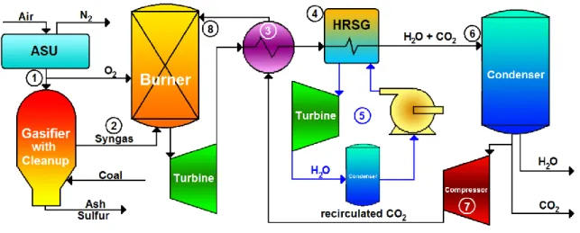
A plant similar to the oxy-fuel combined cycle is known as the CC-Matiant cycle. This cycle is identical to the oxy-fuel combined cycle, except that a recuperator is used on the turbine exhaust before the heat recovery steam generator (HRSG) to warm the gases entering the combustor. (17) Figure 12 presents this cycle layout (note that an oxy-fuel combined cycle has an identical layout if the recuperator step (3) is removed from the flowpath):
25
Figure 12: The CC-Matient cycle
An air separation unit is used to inject oxygen into the burner and gasifier (1). The gasifier turns coal into a syngas and the syngas is passed through cleaup before being injected into the burner (2). After combustion, the products pass through a heat exchanger (3) and then a heat recovery steam generator (4). The steam produced from the HRSG is used to run a rankine steam cycle (5). The cooled exhaust from the HRSG, consisting of only water and carbon dioxide, passes into a condenser (6) where the water is condensed and separated. A portion of the carbon dioxide is then compressed (7), fed through the heat exchanger (3) and injected into the burner (8).
The idea behind the addition of a recuperator in the CC-Matiant cycle is to lower the temperature differences in both the steam generator and the combustor to reduce entropy generation in the cycle. In a study of the cycle, Houyou, Mathieu, and Nihart estimate the efficiency of this cycle at 47-49%. (18) Again, this efficiency does not account for losses in the gasification of coal but is based upon the high heating value of the syngas burned. The recuperator that the CC-Matient cycle proposes has been criticized. It has been suggested that when parasitic losses, including pressure losses of ducting and valves, are taken into account, the recuperator contributes little with
respect to overall plant efficiency, and the capital expenditure for the recuperator unit is not economically justified. (17)
Both cycles suffer from technological limitations. Because of the air separation unit, the working fluid in the turbines is a mixture of carbon dioxide and water, and no
26
nitrogen is present. Current gas turbine technology is designed around streams with nitrogen based working fluids. The necessary changes that would need to be made to current turbine technology would not be minor, with changes in the blade shape, flow area, number of stages, and possible alloy changes necessary to produce a working carbon dioxide-based turbine. (10) Indeed, this would not be a modification of current technology, but an entirely fresh design. In a DOE report produced in February 2004, the current status of carbon dioxide turbomachine technology was summed up by a statement claiming that no gas turbines of this type are available or under serious development. (10) Bolland, in his analysis of oxy-fuel combined cycles, agrees, stating that although a large company could possibly create the needed technology in a five to ten year time span, the technology right now does not exist and will not for the
foreseeable future. (12)
Possible headway on the issue may be made with the help of the nuclear power industry. Researchers are hoping to start using supercritical carbon dioxide to cool nuclear reactors, as opposed to water, which is the current choice. Supercritical carbon dioxide allows smaller (by orders of magnitude) turbomachinery, leading to a more compact and less complex plant layout. Fourteen British nuclear facilities currently operate with carbon dioxide as the cooling medium, although these plants utilize the gas at moderate (650°C) temperatures.
Despite this help from the nuclear industry, severe problems still remain. One large problem is that supercritical carbon dioxide at high temperatures may react and attack the turbomachinery itself. As a result, special materials may be needed to prevent the deterioration of the turbine blades. The nuclear application is also run as a closed cycle, which means they can guarantee a very pure carbon dioxide stream. Turbines for oxy-fuel use, however, will have a water component in the stream greater than 10% by molar mass flow, and the semi-open nature of the cycles will result in other gases and components, including sulfur dioxide, sulfer hydroxide, and methane, among others, being present in the gas flow. The turbine will have to be able to handle the other constituents and be forgiving to the molar fractions of each. Even with these
27
problems, designs have been proposed for high temperature carbon dioxide-based gas turbines for use in oxy-fuel cycles, but none have been built or tested. (19)
Another potential problem that has been brought forth in these cycles lies in the condenser, which separates the water from the carbon dioxide in the exhaust stream. As the water liquefies in the condenser, carbon dioxide, which is readily dissolvable in water at high pressures, will dissolve into the water and form carbonic acid under the following reaction:
CO2 + H2O ⇌ H2CO3
This acid could potentially corrode the condenser walls and require expensive
replacement. (17) At 1 bar, approximately 1% of the carbon dioxide in the exhaust flow will be dissolved in the water. (17) Of this percentage that is dissolved, only a fraction will turn into carbonic acid and pose any threat. Indeed, the equilibrium constant and rate constant at room temperature are 1.7x10⁻³ and 0.039 s-1 respectively, suggesting that roughly 0.2% of the carbon dioxide dissolved in the water will turn into acid, and the water will most likely leave the condenser before the equilibrium is ever reached. (10) As a result, only 2x10⁻⁵ % of the original carbon dioxide in the exhaust path will turn to carbonic acid in the worst case scenario. Despite this seemingly small number, the pH of such a solution can be calculated to be on the order of 4.5, suggesting a moderately acidic outlet solution. This pH value is out of bounds of specs on most common condenser units, and a condenser for this application would likely need a coating of a special alloy to protect against deterioration.
Once this acidic water solution leaves the plant and encounters open air, where the carbon dioxide partial pressure is much lower than in the condenser unit, most of the carbon dioxide dissolved in solution will leave into the atmosphere, leaving a water solution that is nearly acid free. It is this carbon dioxide escape that accounts for the only carbon dioxide emissions of the entire plant.
28
The Water Cycle
The water cycle is a more advanced oxy-fuel combustion cycle that utilizes
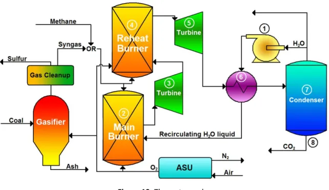
reheat and a recuperator in a Rankine-like power cycle that features water recirculation. Figure 13 shows the cycle layout:
Figure 13: The water cycle
The attractiveness of this design is that the working fluid, which is mostly water, is compressed to its highest pressure of 83 bar in the liquid phase (1), vastly reducing the energy requirements for compression. (16) In the combustor at 83 bar, the liquid water is flashed into steam and heated to 1173 K through the combustion process (2) and
expanded to 8.3 bar in a high pressure steam turbine (3). The water is then passed through a reheating combustor where it is heated to an exhaust temperature on the order of 1573 K (4). After expansion to 0.1 bar (5), the stream is passed through a recuperator (6), condensed (7), and carbon dioxide is removed (8). Some of the water is also removed before it is pumped to 83 bar (1), sent through the recuperator (6), and fed into the combustor. (16) The entire cycle is fed with a gasifier running on coal that cleans the syngas of sulfur before injection into the burner. Like all oxy-fuel designs,
29
combustion is done stoichiometrically with only oxygen, so an air separation unit is required to provide the oxygen to the burners and the gasifier.
Analysis on this type of power cycle has produced estimated efficiencies in the lower 40% range, including carbon dioxide liquefaction. (17) Again, it is important to note that these efficiencies do not account for losses in coal gasification. Bolland, Kvamsdal, and Boden, in their analysis of the water cycle, note that the overall efficiency of the plant is highly sensitive to the outlet pressure of the first combustor, claiming 0.7-1.3 percentage point efficiency gains for each 100 degrees K the temperature is raised. (17) By their calculations, a high pressure of 200 bar with an exit temperature from the combustor of 1673 K would produce a total plant efficiency of 53%. (17)
This leads directly into the largest problem with the water cycle. The cycle is designed to use water as a working fluid in order to take advantage of steam turbines, which are a mature technology. Unfortunately, the best steam turbines cannot handle the high pressures and temperatures needed to push the efficiency values beyond those of simple post-combustion technology. It is suggested that steam turbine technology can perhaps be mixed with high pressure and temperature gas turbine technology to produce a working prototype plant capable of 50% efficiencies, but it is recognized that current technology places the plant at the 40% efficiency level. Much work and
research would have to be done to reach a level where the plant can reach higher efficiency. (16) Such technologies would take many years to develop and the investment would most likely not be sound, considering the alternative carbon capture technologies have development times promised to be some years less. (17)
The Matiant Cycle
The matiant cycle makes use of a regenerative Brayton-like cycle with a supercritical CO2 Rankine-like cycle with carbon dioxide recirculation. Its layout is similar to that of the water cycle, with some exceptions being that carbon dioxide is the working fluid being recirculated, and the pressures and temperatures at each stage are different. Figure 14 shows the cycle layout:
30
Figure 14: The Matiant cycle
Supercritical CO2 at 300 bar is heated in a recuperator (1) before being expanded in a gas turbine to 40 bar (2). After this stage, the gas is heated again through a second recuperator (3) before being burned in a high pressure combustor at 40 bar to 1573 K (4). After passing through a gas turbine and being dropped to 9.3 bar (5), the gas is reheated in a reheat combustor to a temperature of 973 K (6). The fluid expands through a second turbine to 1 bar (7) before losing more energy to the recuperator that heats the supercritical CO2 (1 and 2). After this stage, water is condensed (8) and removed before the carbon dioxide is compressed in an intercooled compressor to 70.5 bar and liquefied at 302 K (9). After excess carbon dioxide is removed, the liquefied CO2 is then pumped (10) to 300 bar and passed into the recuperator (1).
The attractiveness of this cycle is that the carbon dioxide can be pumped in its liquid phase to 300 bar, saving compression work. Analysis of this cycle by Mathieu and Nihart finds efficiencies between 44-45%. (20) This efficiency figure does not take into account losses associated with the gasification of coal.
The Matiant cycle faces the most daunting technological challenges of all the proposed fuel cycles. Although it faces the same technological hurdles as the oxy-fuel combined cycle plants with respect to CO2 based gas turbines, the Matiant cycle has an additional hurdle in the production of a supercritical CO2 turbine that can expand the fluid from a high pressure of 300 bar and a temperature of 873 K. The cycle architects
31
suggest that such a turbine could be adapted from current steam based turbines in UltraSuperCritical Rankine type cycles within a 2-3 year timeframe, (20) but it seems that this prediction is overly optimistic. At the very least, this cycle design requires the invention of more new technologies than many other proposed layouts.
Another problem associated with this cycle scheme is the requirement of large amounts of internal heat exchange between hot streams. In particular, the exhaust stream that is cooled enters the heat exchange equipment at 1 bar and 1200 K, which implies problems for the heat exchanger technology. (17) It is highly likely that cooling would be needed to control the temperature of the heat exchange equipment, which would introduce additional efficiency penalties beyond what is currently considered. The size and capital costs of these heat exchangers could also prove problematic. Here again, as with the carbon dioxide based turbines, the nuclear industry is of help. The cycle designs being considered in the nuclear industry include the use of supercritical carbon dioxide heat exchangers of the type necessary for use in these cycles as well. Some proposed designs in the nuclear field include the use of printed circuit heat exchangers instead of shell and tube style heat exchangers. The printed circuit version allows a large reduction in size and capital expenditure for the same heat exchanger effectiveness.
In addition, analysis on this plant design by Bolland et al has shown that it is highly sensitive to parasitic losses and an actual working model of the plant may produce far lower efficiency values than calculated due to unforeseen losses. (17) It is noted that the intercooled compressor is of extreme importance to the cycle, and a drop in isentropic efficiency of 10% for the compressor stack results in a 5% drop in efficiency for the entire plant, and it is openly questioned whether the 90% isentropic efficiency value assumed by the cycle architects is too high. (20)
The E-Matiant Cycle
A cycle based upon the Matiant cycle attempts to address many of the issues with the matiant cycle itself. The E-matiant cycle is a fully Brayton type cycle that removes the high pressure expander and eliminates the reheat combustor. The carbon
32
dioxide in this cycle stays entirely in the gaseous phase and is totally compressed through an intercooled compressor stack. The maximum pressure in this cycle is reduced to 110 bar. Figure 15 shows the cycle layout:
Figure 15: The E-Matiant cycle
A cleaned syngas from a gasifier enters the burner (1) and combusts. The
exhaust gas, consisting of only carbon dioxide and water, is passed through a turbine (2) and then a recuperator (3) before passing into a condensor (4). The carbon dioxide is compressed in a staged intercooled compressor (5) before a portion is heated in the recuperator (3). This gas is then fed back into the burner to control combustion temperatures (1).
Cycle analysis by Houyou, Mathieu, and Nihart places the cycle efficiency in the 47% range. (18) This efficiency value does not include losses associated with the coal gasifier. The major draw to this design is that it eliminates the high pressure and temperature supercritical CO2 turbine that would have had to have been developed for the Matiant cycle. It makes the production of a CO2 gas turbine more difficult, however, by pushing its high pressure from 40 bar at the combustor outlet to 110 bar. There is also trouble with producing a combustor and associated equipment that can operate at 110 bar. In addition, the cycle still contains large amounts of internal heat exchange equipment and its overall efficiency is still highly dependent upon the isentropic
33
Like the traditional Matiant design, it is doubtful that an actual plant utilizing this cycle would come close to the theoretical efficiency values claimed here.
The Graz Cycle
The Graz cycle is another innovative oxy-fuel combustion method that is
essentially a high temperature Brayton cycle combined with a low temperature Rankine cycle. (21) Figure 16 shows the plant layout:
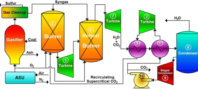
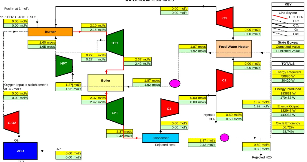
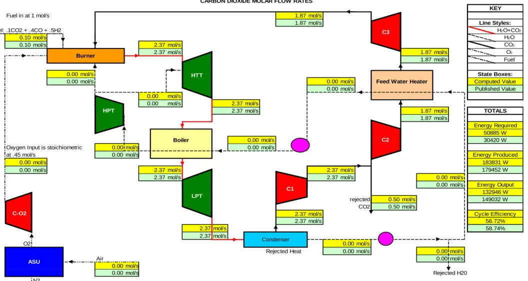
Figure 16: The Graz cycle
The cycle utilizes recirculation of both water and carbon dioxide from the exhaust stream into the combustor to control flame temperatures and produce a humid carbon dioxide working fluid. The combustor operates at 40 bar and increases the exhaust to 1623 K (1). After the burner, the gas is expanded to 10 bar (2a) before more
recirculated water is added to the stream (3). The fluid is then expanded to 1 bar (2b) before passing through a boiler where it loses heat to a water stream (4). After this point, the gas is expanded once more to .25 bar (5) where it passes through a condenser to separate the carbon dioxide and water (6). After this separation, the carbon dioxide is compressed to 1 bar and excess CO2 is removed for later liquefaction and storage (7).
34
The remaining CO2 is compressed to 2.7 bar (8) before passing through a heat exchanger where it gives up heat (9). It is then finally compressed to 40 bar and fed back into the burner (10). The water from the condenser is pumped to 5 bar before excess water is removed (11). The remaining water is heated in the heat exchanger (9) before being pumped to a high pressure of 180 bar (12). The water is then sent through the boiler where it is turned to gas and heated to 840 K (4). The stream is passed through a high pressure steam turbine and dropped to a pressure of 40 bar before being inserted into the burner (13).
Analysis of the cycle by Heitmeir, Sanz, Göttlich, and Jericha in one paper and Bolland et al in another places the cycle efficiency, including CO2 liquefaction, in the 50-52% range. (17) (21) This cycle efficiency does not include the efficiency penalty associated with the gasification of coal.
The use of gas turbines in this cycle based on a CO2 dominated working fluid presents the same problems that the oxy-fuel combined cycle and Matiant cycle face with respect to CO2 gas turbine production. The cycle is also rather complex, and it is unclear whether the capital costs for a plant of this complexity would make it
economically viable. In addition, this plant fails to incorporate a liquefaction plant for the CO2, something the Matiant cycle does, and also fails to integrate with the gasifier used to produce syngas from a coal, a problem that all these cycles face.
The high pressure steam turbine, asked to bring steam from 180 bar and 560°C to 40 bar, is also of concern. These entry requirements are higher than what off-the-shelf steam turbine technology is able to offer.
A Comprehensive Study of the Graz Cycle
The choice of the Graz cycle
Despite its problems, the Graz cycle represents the most promising of all
proposed oxy-fuel carbon capture technologies. Although the theoretical efficiency for the Graz cycle is high, this alone is not what sets it apart from the other designs. Indeed, all of these designs exist only within simulation programs and complex models,
35
and as such the calculated efficiency numbers will not be accurate when compared to what a plant would produce in the real world. Most of these plants claim efficiencies within 10 percentage points of one another, and as such theoretical efficiency alone would not be a proper metric to determine the most promising cycle design.
The Graz cycle’s other advantages lie in its feasibility. The difficulties faced by the Graz cycle in producing a high pressure steam turbine prove easier to solve than the same problems faced by the water cycle. Despite requiring very high pressures, like the water cycle, the input temperature in the Graz cycle, although high, is hundreds of degrees lower than that of the water cycle. With the advent of super-critical rankine cycles that utilize steam turbines operating at higher temperatures and pressures, there is promise that a turbine usable in the Graz cycle may be available faster than a
comparable turbine for the water cycle.
The Matiant cycle requires the development of a supercritical CO2 turbine based on current steam turbine designs. Although this technology may be feasible, it has no other applications to other cycles and therefore carries significant risk for investment. This is especially true if one accepts the arguments of Bolland et al that the cycle is highly sensitive to both parasitic losses and changes in the compressor isentropic efficiency from the assumed value. The E-Matiant cycle suffers from these same vulnerabilities.
The remaining technical challenges, including the development of carbon dioxide based turbines and acidic water in the condenser, are not unique to the Graz cycle, and all the other oxy-fuel cycles require the same technological innovation and investment that would be required for the Graz cycle in these areas. The Graz cycle has the most promise since it offers the highest efficiencies among these cycles. The advantage of focusing on producing the Graz cycle is that should the cycle prove unrealistic in the real world, the technology invested in its development can be used elsewhere in other oxy-fuel designs.
When comparing the Graz cycle to pre- and post-combustion designs, other factors must be considered. If near total CO2 capture is desired, it is clear that only the
36
oxy-fuel combustion technologies are viable, since both pre-combustion and post-combustion cycles offer only 90% carbon capture at theoretical efficiencies at or below what is claimed by the oxy-fuel combustion cycles. Post-combustion capture technology also represents a ‘band-aid’ measure that does not integrate the carbon removal
process in the overall cycle. This lack of integration causes inefficiencies and possible points of entropy generation due to this decoupling. As a result, traditional cycles employing post-combustion capture will never be able to approach the efficiency levels of an oxy-fuel or pre-combustion cycle, which make it unattractive as a design for new power generation plants.
Pre-combustion technology offers significant promise in its ability to produce cheap power with carbon capture. With the DOE soon to put out bids on its FutureGen project, a test plant in the Unites States based on this technology is not far off. These cycles have the advantage of using existing technology and layouts, emulating
integrated combined cycle (IGCC) plants in many ways. As a result, they are very desirable from a risk standpoint, since there are parallels that can be drawn between the theoretical operation of these plants and the actual operation of IGCC plants worldwide.
Yet the Graz cycle represents a radical idea and a complete rethinking of the power cycle with carbon capture in mind. If computer based models prove to be accurate, the cycle will operate with very high efficiencies with virtually no pollutant release, including carbon dioxide. Investment in the Graz cycle represents a higher risk, since no plants of this type have ever been built and their operation is not well
understood. But with significant funding going into the pre-combustion capture sector, it is wise to focus some resources on unconventional designs that, despite the risk, offer the possibility of substantial payoff and reward in the future.
The Graz cycle is analyzed in detail here in an effort to start this process and help ensure that human investment in a world free of carbon dioxide emissions is diversified.
37
Building a Cycle Model
The analysis of the Graz cycle in this paper is based upon a model developed specifically for the Graz cycle itself. Published documents from the developers of the Graz cycle and other researchers working with the cycle were used to validate this model, which was then used as a basis of further cycle analysis and optimization.
The model was developed using Microsoft Excel 2007 as a graphical frontend. Visual Basic scripts were written to interface with Excel and perform the necessary calculations. The scripts also interfaced with the National Institute of Standards and Technology Standard Reference Database 23: Reference Fluid Thermodynamic and Transport Properties Database Version 7 (NIST REFPROP 7), which provided the thermodynamic data for water, carbon dioxide, oxygen, carbon monoxide, and hydrogen. This database was used to calculate specific state variables, including enthalpy, entropy, pressure, and temperature, of the working fluids in the cycle as a function of any two of the other state variables. The NIST REFPROP 7 database was also used to calculate state variables of mixtures of fluids, most notably the mixture of carbon dioxide and water in the exhaust stream of the Graz cycle burner. The value of an overall specific property for a mixture, such as its specific heat or specific enthalpy, was determined by multiplying the specific property of each individual constituent in the mixture by that constituent’s molar fraction, and then adding the results:
where ψ is the specific property of the mixture and ψn and χn are the specific property
and molar fraction of specie n. The database was also used to calculate various transport properties, including specific heat capacity of mixtures and streams.
Turbomachines were modeled in the system using a standard process: the enthalpy change for an isentropic process was found, and this enthalpy change was multiplied by a component efficiency, η:
38
With this new enthalpy change for the turbomachine, a true output temperature for the working fluid was calculated using its mass flow rate, , and its specific heat capacity,
cp:
Heat exchangers were modeled using the heat exchanger effectiveness, ε, to find the heat load, Q:
where Cmin is defined as the smaller heat capacity of the hot and cold streams, and Thotin and Tcoldin are defined as the inlet temperature for the hot and cold stream,
respectively. The model then uses the heat load, the mass flow rates of the hot and cold streams, and the heat capacities of the hot and cold streams to determine the hot and cold stream exit temperatures, Thotout and Tcoldout:
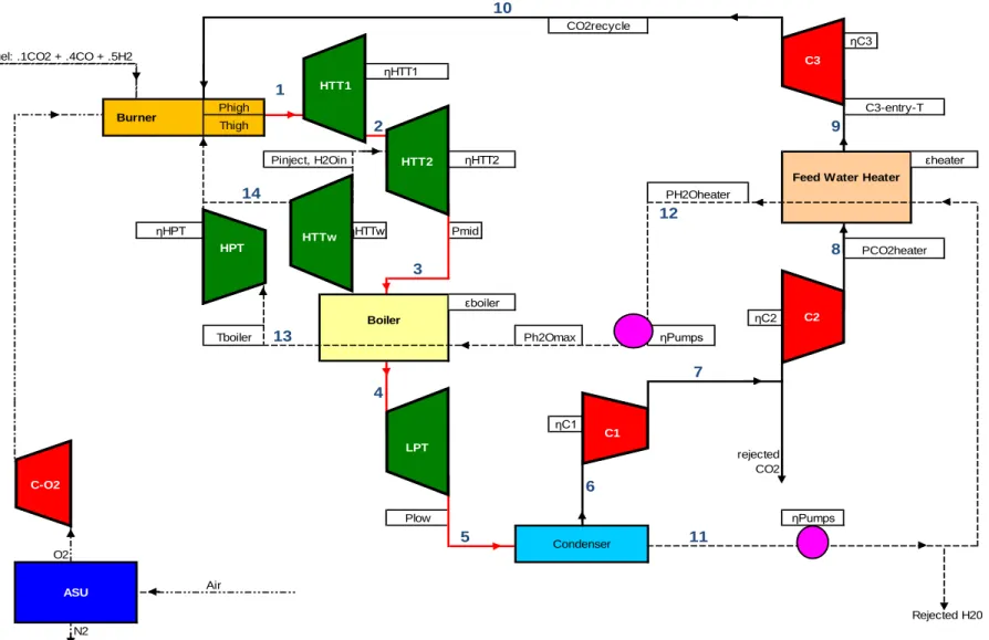
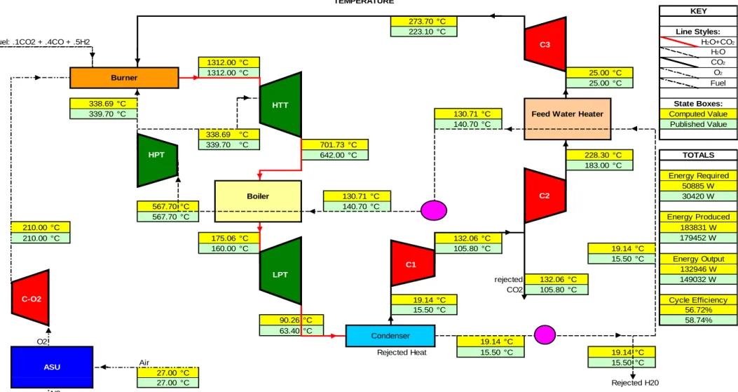
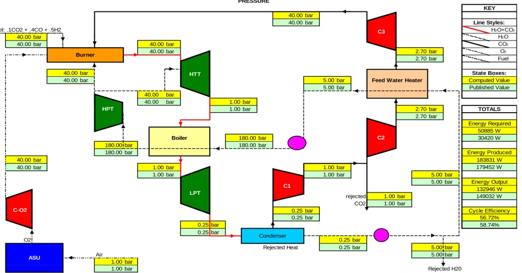
In defining the cycle, this model assumed 23 independent variables that fully defined the system. Table 1 enumerates these variables, along with values used for this analysis, derived from a study of the Graz cycle performed by Jericha and Goettlich. (22) All the pressure and temperature values were taken directly from the Jericha paper,
39
while efficiency, effectiveness, and recycle percentage values were calculated using first order means from the published input and output states. Figure 17 shows the location of these state variables on the Graz cycle flowchart.
Table 1: Independent variables used in model
Variable Description Value Unit
Phigh System high pressure in the combustor 40 bar
Thigh Output Temperature of the combustor 1312 °C
Pinject Pressure at which water is injected into exhaust 10 bar
H2Oin Molar mass flow of water injected into exhaust 0.27 mol/s
Pmid Pressure of the exhaust stream in the boiler 1 bar
Plow Low pressure of the system in the condenser 0.25 bar
Tboiler Water output temperature from the boiler 567.7 °C
PCO2heater Pressure of CO2 in the feed water heater 2.7 bar
PH2Oheater Pressure of H2O in the feed water heater 5 bar
PH2Omax Maximum pressure of H2O in the boiler 180 bar
CO2recycle Percentage of CO2 recycled back to burner 78.9 %
C3-entry-T Temperature of CO2 at entry to third compressor 25 °C
ηHTTw Efficiency of the injected water turbine 89.8 %
ηHTT1 Efficiency of the first stage of the HT turbine 85.5 % ηHTT2 Efficiency of the second stage of the HT turbine 86.16 %
ηLPT Efficiency of the low pressure turbine 75.37 %
ηHPT Efficiency of the high pressure turbine 89.14 %
ηC1 Efficiency of the first compressor 90 %
ηC2 Efficiency of the second compressor 90 %
ηC3 Efficiency of the third compressor 90 %
ηPumps Efficiency of the water pumps 98.83 %
εboiler Effectiveness of the boiler 90 %
40 10 ηC3 1 Phigh Thigh 2 9 14 12 Pmid 8 3 ηC2 Tboiler 13 7 4 ηC1 6 Plow ηPumps 5 11 O2 Air Fuel: .1CO2 + .4CO + .5H2
ηHTT1
ηHTT2
Feed Water Heater
Boiler εboiler ηPumps rejected Condenser ASU Rejected H20 N2 CO2recycle Burner C3-entry-T
Pinject, H2Oin εheater
PH2Oheater ηHPT PCO2heater Ph2Omax CO2 ηHTTw HPT HTT2 LPT C1 C2 C3 C-O2 HTTw HTT1
41
In addition to these independent variables, the following values, shown in Table 2, are taken in the model as constants:
Table 2: Constant values in the Graz cycle model
Variable Description Value Unit
HHVfuel The higher heating value of the input syngas 234.409 KJ/mol
Fuel-makeup The fuel: 0.1CO2 + 0.4CO + 0.5H2 1 mol/s
CO2exitP
The exit pressure of rejected CO2 before liquefaction
(NOTE: constant because a change here results in an
offsetting change elsewhere) 1 bar
O2 work Work done by the oxygen compressor 5880.45 W
ASU work Work done by the Air Separation Unit 7280.13 W
Another unknown, Tlow, defined as the temperature at the outlet of the
condenser, is a dependant variable that is a function of the pressure in the condenser,
Plow, and the mass fraction of water in the condenser stream. The temperature here
must be low enough to allow water to condense out of the stream, and this
temperature is based on the partial pressure of the water at the inlet. This value is calculated by the model according to the following state equation, provided by the NIST REFPROP 7 libraries:
where,
In the burner, the HHV of the fuel was used as a heat input, and the combustion products were taken to be at 25°C. The molar flow rate of carbon dioxide into the burner, defined through the independent variables, was used with an estimate of the