Publisher’s version / Version de l'éditeur:
Vous avez des questions? Nous pouvons vous aider. Pour communiquer directement avec un auteur, consultez la première page de la revue dans laquelle son article a été publié afin de trouver ses coordonnées. Si vous n’arrivez pas à les repérer, communiquez avec nous à PublicationsArchive-ArchivesPublications@nrc-cnrc.gc.ca.
Questions? Contact the NRC Publications Archive team at
PublicationsArchive-ArchivesPublications@nrc-cnrc.gc.ca. If you wish to email the authors directly, please see the first page of the publication for their contact information.
https://publications-cnrc.canada.ca/fra/droits
L’accès à ce site Web et l’utilisation de son contenu sont assujettis aux conditions présentées dans le site LISEZ CES CONDITIONS ATTENTIVEMENT AVANT D’UTILISER CE SITE WEB.
Proceedings of the 8th International Symposium on Fire Safety Science, pp.
247-258, 2005-09-01
READ THESE TERMS AND CONDITIONS CAREFULLY BEFORE USING THIS WEBSITE. https://nrc-publications.canada.ca/eng/copyright
NRC Publications Archive Record / Notice des Archives des publications du CNRC :
https://nrc-publications.canada.ca/eng/view/object/?id=a0920e3a-a75c-4e89-9126-5d6b43006e75 https://publications-cnrc.canada.ca/fra/voir/objet/?id=a0920e3a-a75c-4e89-9126-5d6b43006e75
NRC Publications Archive
Archives des publications du CNRC
This publication could be one of several versions: author’s original, accepted manuscript or the publisher’s version. / La version de cette publication peut être l’une des suivantes : la version prépublication de l’auteur, la version acceptée du manuscrit ou la version de l’éditeur.
Access and use of this website and the material on it are subject to the Terms and Conditions set forth at
An Investigation on fire performance of FRP-strengthened R/C beams
http://irc.nrc-cnrc.gc.ca
An I nve st igat ion on fire pe rfor m a nc e of
FRP-st re ngt he ne d R/C be a m s
N R C C - 4 7 6 4 2
W i l l i a m s , B . ; B i s b y , L . ;
K o d u r , V . ; S u , J . ; G r e e n , M .
A version of this document is published in / Une version de ce document se trouve dans:
Proceedings of the 8th International Symposium on Fire Safety Science, Beijing, Sept. 18-23, 2005, pp. 247-258
An Investigation on Fire Performance of
FRP-strengthened R/C Beams
BREA WILLIAMS1, LUKE BISBY2, VENKATESH KODUR3, JOSEPH SU3, and MARK GREEN2
1
Technical Team Member Halsall Associates Ltd. 3001-210 Gladstone Avenue Ottawa, Canada
2
Faculty Member
Dept. of Civil Engineering Queen’s University Kingston, Canada 3
Senior Research Officers Fire Risk Management Group Institute for Research in Construction National Research Council of Canada Ottawa, Canada
ABSTRACT
As the use of Fibre-Reinforced Polymer (FRP) materials continues to expand into the structural repair market, concerns over the performance of these materials in fire conditions are now at the forefront of research. While externally bonded FRP sheets have been shown to successfully enhance the flexural and shear capacity of bridges and other structures, their application in interior spaces, where fire is a significant concern, remains questionable in light of these materials’ comparatively poor resistance to elevated temperatures. This paper presents the results of an ongoing study to document the performance of FRP-strengthened reinforced concrete beam-slabs exposed to fire. With such experimental results, fireproofing materials have the potential to earn standard performance ratings, which are essential to the design engineer and necessary for the continued increase of FRP applications worldwide.
A brief synopsis of existing literature related to FRP behaviour at high temperature is provided, in addition to a review of the current fire endurance criteria for structural members. Two large-scale concrete beam-slab assemblies were strengthened with FRP sheets and protected with a two-part patented fire insulation system. The results of fire tests performed on these specimens are presented herein, with emphasis placed on the temperatures measured in the specimens during fire exposure. The data obtained from the tests served to validate a numerical heat transfer model, which predicts the temperature within a strengthened and insulated reinforced concrete beam-slab assembly. Test results and model data indicate that appropriately designed and insulated FRP-strengthened beam-slab assemblies can achieve fire endurances of four hours or more.
KEYWORDS: fibre-reinforced polymer (FRP), structural fire endurance, reinforced
NOMENCLATURE
c specific heat (J/kg-K) φ moisture content of element
k thermal conductivity (W/m-K) Subscripts
∆l length of element (mm) c concrete
∆t time increment (hours) f fire
Tg glass transition temperature (ºC) m refers to adjacent node “m”
Greek r refers to adjacent node “r”
εc emissivity of concrete = 0.9 w water εf emissivity of fire = 1.0 Superscripts
ρ density j previous time step
σ Stefan-Boltzmann constant j+1 current time step INTRODUCTION
The rapidly deteriorating state of the world’s infrastructure has promoted recent innovations in materials science. In an effort to rehabilitate deteriorating structures, repair under-strength members and offer durable new construction materials, FRP materials have been adapted from their more conventional applications in the aerospace industry, and are now being applied in civil engineering. FRP products, which consist of fibres (carbon, glass, aramid) in a polymer matrix (epoxy, vinyl ester), offer lightweight, high strength, corrosion resistant alternatives to conventional building materials. FRP materials are also highly versatile; available as bars, tendons, sheets, tubes and many other custom forms. Over the past 15 years, research initiatives around the world have demonstrated the viability of FRP sheets for use in repair and rehabilitation schemes for concrete structures. Externally-bonded FRP sheets have been shown to successfully enhance the strength and ductility of reinforced concrete columns [1,2,3,4], and to achieve increased flexural and/or shear strength in reinforced concrete beams [5,6]. In beam applications, FRP sheets are bonded to the base of the beam web or to the face of the web to gain strength in bending or shear, respectively
FRP at Elevated Temperature
While structural steel members require protection to preserve their strength in a fire event, FRP-strengthened concrete beams require protection to maintain their strength, to prevent combustion of the material, and, to a lesser extent, to preserve their bond with the substrate. The introduction of FRP into a new field of application brings with it a host of technical obstacles; one concern at the forefront of FRP research is related to the performance of FRP-strengthened members in fire. The organic polymer matrices of FRP make them susceptible to combustion when exposed to fire. The critical temperature is the glass transition temperature (Tg); defined as the threshold at which an FRP’s properties begin to change significantly. When Tg is exceeded, the polymer matrix becomes soft and rubbery [7], with reduced strength [8]. Many commonly used thermoset matrices exhibit a Tg in the range of 65-82ºC [9]. At even higher temperatures polymer matrices may ignite, supporting flame spread and toxic smoke evolution [10].
The structural integrity of FRP materials after exposure to fire is not well known. However, a study [11] was performed recently to define the temperature at which only 50% of the original room temperature strength of an FRP material remains. Based on 57 tension tests conducted at various increasing temperatures, it was determined that
carbon and glass FRPs lost 50% of their strength at 250ºC and 325ºC, respectively. Stiffness appeared to suffer negligible losses up to about 400º, above which point it decreased rapidly. A recent literature survey conducted by Bisby [12], and updated by Williams [13], compiled temperature-dependent strength and stiffness data for FRP from a number of studies and proposed predictive equations, based on a least-squares regression analysis, to describe the observed trends. The equations were assumed to be sigmoidal in nature. Figure 1 shows the individual data points used in the regression analysis along with the predictive sigmoid curve for FRP strength. While the curve reveals the general trends in the data, it is a rough approximation since many different specific types of FRP materials are represented in the data.
0 20 40 60 80 100 120 -50 50 150 250 350 450 550 Temperature (deg. C) % Retained
PAN Carbon / Epoxy 1 (1) PAN Carbon / Epoxy 2 (1) PAN Carbon / Epoxy 3 (1) Pitch Carbon / Epoxy 1 (1) Pitch Carbon / Epoxy 2 (1) Braided Carbon / Epoxy (4) Stranded Carbon / Epoxy (4) Braided Carbon / Epoxy (5) Spiral Carbon /Epoxy (5) Carbon / Epoxy (6) Carbon / Epoxy (7) Carbon / Epoxy-Phenolic (7) Carbon / Epoxy (8) Pitch Carbon / Cement (1) Carbon / Inorganic (5) Carbon / Glass / Vinyl Ester (2) Carbon / Glass / Vinyl Ester (3) Carbon / Polyimide (7) Idealized Carbon / Epoxy
(5) Tanano et al., 1995 (6) Sumida et al., 2001 (7) Dimitrienko, 1999 (8) Wang et al., 2003 R2=0.524 (1) Kumahara et al., 1993 (2) Rahman et al., 1993 (3) Fujisaka et al., 1993 (4) Tanano et al., 1997
Fig. 1. Variation in strength with temperature for various carbon Fibre Reinforced Polymers [12,13]. Standard Fire Testing
Due to the random nature of fire, standard fire conditions have been prescribed in fire testing codes to represent typical severe fires in the lab setting. In a fire test in North America, a structural member must be subjected to standard temperature-time conditions as described by ASTM E119 [14], which reaches temperatures in excess of 1000ºC after two hours. The main parameter of interest measured in a structural fire test is a specimen’s fire endurance, which is defined as the length of time that a structure or member withstands exposure to the fire without losing its load-bearing or fire separating capacities. For the flexural specimens evaluated in this paper, ASTM E119 defines fire endurance as the time during which the following criteria are satisfied:
1. The member is capable of withstanding its applied load;
2. The reinforcing steel in the concrete maintains a temperature less than 593ºC; and 3. The average unexposed surface temperature does not rise more than 140ºC and no
Related Research
While a significant amount of testing has been conducted on FRP materials in isolation at high temperatures, these results cannot be directly extrapolated to predict the fire performance of concrete strengthened with FRP sheets. Moisture content, temperature and stress in the concrete member affect the fire performance and should be taken into account. To date, two research groups [15,16] have performed tests similar to those presented in this paper. Deuring [15] and Blontrock et al. [16] exposed reinforced concrete beams with a number of strengthening and insulation configurations to fire. In the first group of tests [15], it was found that a specimen without strengthening withstood fire for 118 minutes. An FRP-strengthened concrete beam without protection displayed 81 minutes of fire resistance, whereas the same beam with a 40 mm-thick protection of calcium silicate board applied to the exterior of the FRP improved its fire endurance by 1.8 times over the unprotected specimen. In the second set of tests [16], the effects of varying protection thickness, location, method of bonding, and length were studied. A beam with calcium silicate board insulation anchored by adhesive lost its bond after only 7 minutes of fire exposure, while mechanically anchored insulation maintained its protective capacity for 45 minutes. It was determined that U-shaped fire protection provided more effective insulation for the FRP-strengthened beams. Finally, insulation applied only within the anchorage zone of the FRP sheets, preserved the bond sufficiently to allow the CFRP sheet to maintain its contribution as tensile reinforcement well into the test (38 minutes), in a manner similar to the fully protected beams.
EXPERIMENTAL PROGRAM
Researchers at Queen’s University at Kingston, Canada, the National Research Council of Canada (NRC), and Fyfe Co. LLC collaborated in an attempt to quantify the thermal and structural behaviour of FRP-strengthened reinforced concrete beams subjected to fire conditions. This project involved the design and fabrication of two large-scale beam-slab assemblies, both of which were strengthened with FRP, protected with a patented insulation system, loaded to service load levels, and exposed to the ASTM standard fire. Specimens, Strengthening and Protection
Figure 2 shows a cross section of the beam-slab assembly. Two beams were fabricated, spanning 3.8 m, with cross sectional dimensions selected to satisfy ASTM requirements [14], and to be representative of field conditions. The beams were reinforced to resist self-weight and a 2.4 kPa live load. The same concrete mix design was used for both beams, and included 16 mm limestone aggregate and a 28-day design compressive strength of 41 MPa. The measured relative humidity of the specimens at the test date was 73%.
The FRP strengthening scheme was devised assuming that an increase in live load to 4.8 kPa was required. Both beams were strengthened with a 100 mm wide strip of Fyfe Co. Tyfo® SCH composite strengthening system, applied to the soffit of the web over the entire beam span. The composite consisted of a carbon reinforcing fabric and a two-part epoxy saturant/adhesive, applied using a hand lay-up procedure. A 1.3 mm-thick SCH laminate possesses a design tensile strength of 460 MPa in the direction of the fibres, and an ultimate elongation of 2.2% at failure. To enhance the bond of the flexural sheet in fire, a U-wrap of Fyfe Co. Tyfo® SEH glass/epoxy FRP sheet was applied to the
anchorage zones (600 mm in length) of the beam. This strengthening resulted in an approximate 15% increase in the flexural capacity of the beams.
Fig. 2. Cross section schematic of beam-slab assembly.
Fire protection for both beams consisted of a two-part system consisting of Fyfe Co. Tyfo® VG insulation and Fyfe Co. Tyfo® EI-R coating. VG is a lightweight, fire resistant cementitious plaster that was spray-applied to the underside of the beams. Materials similar to VG have been used in the past to fireproof structural steel members. As shown in Fig. 2, the VG was applied to three sides of the beams’ webs, and extended to the underside of the slabs, along the entire beams’ length. EI-R is an impermeable surface-hardening layer that was spray-applied over the installed VG layer. Beam 1 was protected with 25 mm of VG insulation, while Beam 2 had a VG thickness of 38 mm. Both beams had an EI-R thickness of approximately 0.13 mm. Table 1 summarizes the properties of the VG. The EI-R coating has been ignored in the thermal analysis since it has been observed to burn off rapidly in fire, and its overall effects on heat transfer are thus considered negligible.
Table 1. VG insulation properties.
Property Value ASTM Test
Density, kg/m3 240-272 -
Compressive strength, kPa 112.0 E 761
Bond strength, kPa 18.6 E 736
Combustibility Non-combustible E 136
Surface flame spread 0.0 E 84
Effect of impact Passed E 760
Effect of deflection Passed E 759
Thermal conductivitya, W/m-ºC 0.00815 -
Specific heata, J/kg-K 1047 -
a
Approximate room temperature data based on previous research [17]
Test Setup
The two beams were tested simultaneously in the full-scale floor furnace at NRC. They were secured in a steel ring frame that was subsequently placed on top of the furnace chamber; exposing the web and lower slab face of the beams to fire from below while the top of the slabs were exposed to ambient conditions. The ends of the beams were axially restrained, though this fixity did not translate into full moment fixity at the supports. It
1220 300 150 250 All reinforcement 10mm dia. unless otherwise specified 20mm dia. steel rebar 40mm clear cover 100 125 All dimensions in mm Carbon FRP sheet Insulation Sealant (VG) (EI-R)
was anticipated that the axial restraint provided by the steel ring beam would enhance the fire endurance of the beams during fire testing, as is suggested in the fire testing literature [18]. The required superimposed load was determined according to standard methods [19], and applied to the unexposed surface using a series of 12 hydraulic jacks, to a load level representing 56% of the ultimate capacity of the concrete beams alone, and 48% of the ultimate capacity of the strengthened beams. Finally, each beam-slab assembly was instrumented with 36 thermocouples located within the concrete, at the unexposed surface, and within the FRP and insulation layers, to monitor the transfer of heat during the test.
EXPERIMENTAL RESULTS
Through small viewports in the furnace walls, it was observed that limited surface flaming (combustion) of the EI-R layer occurred in the first four minutes of the test. Localized cracking of the VG occurred around 60 minutes of fire exposure, likely related to accidental unloading and reloading of the beams resulting from a minor problem with the hydraulic system. At four hours of fire exposure, the applied load on the beams was gradually increased to twice the original load level in an effort to induce structural failure. As failure did not appear imminent while applying the maximum possible load, the test was stopped at 267 minutes.
Temperatures
The temperatures measured in the insulation and FRP strengthening layers of Beams 1 and 2 are shown in Fig. 3.
Fig. 3. Temperatures in Beams 1 and 2.
The temperature at each interface was measured at three points along the span of each beam, and has been averaged for comparison purposes. The furnace temperature strayed slightly from the standard temperature-time curve due to low (sub-zero) ambient temperatures and the large mass of the assemblies. Initially, the temperature at the EI-R/VG interface rose rapidly due to burning-off of the EI-R layer, but then followed the trend of the furnace temperature for the remainder of the test. The temperature at this interface was nearly identical for the two beams, which is to be expected since both were protected with the same thickness of EI-R coating. At the VG/FRP interface, the temperatures rose at a slower rate, as expected, and again essentially followed the
Time [minutes] 0 60 120 180 240 Temperature [ºC] 0 200 400 600 800 1000 1200
Avg. Furnace Temp. EI-R/VG VG/FRP FRP/Concrete ASTM E119 Beam 1 Beam 2
temperature in the furnace. Unexpected rises in temperature were observed at this location and were likely due to localized cracking of the VG, which would allow more rapid heating of the underlying FRP layer. Due to a greater thickness of VG insulation, Beam 2 recorded slightly lower temperatures at this interface than Beam 1. The temperature at the FRP/concrete interface (the FRP/concrete bondline) is presumed to be an important indicator of the ability to maintain bond between the FRP strengthening system and concrete substrate during fire. Figure 3 shows that temperature at this location increased at a slower rate than at any other location, and evaporation of moisture in the VG layer, as evidenced by the temperature plateau around 100ºC, assisted in maintaining a lower temperature for a longer period of time. After four hours of fire exposure, the average FRP bondline temperature was 361ºC and 220ºC in Beams 1 and 2, respectively. Fire Endurance
Both beams resisted their applied load for over four hours of fire exposure. However, equally important in defining fire endurance is the application of the thermal criteria of ASTM E119 [14]. The maximum recorded steel reinforcement temperatures of 561ºC (Beam 1) and 540ºC (Beam 2) were less than the maximum allowable temperature of 593ºC for the full test duration. Note that these maximum temperatures were measured in the slab portion of the section, while the steel rebar in the web portion reached only a maximum temperature of approximately 250ºC and 200ºC in Beams 1 and 2, respectively. In addition, the individual point and average unexposed temperatures at the unexposed face of the beams were less than the maximum allowable temperature increases of 180ºC and 140ºC, respectively. Since load and temperature criteria were satisfied for the full test duration, both beams earned four hour fire ratings. At this time, fire testing provisions do not exist to limit the temperature of an FRP strengthening system during exposure to fire. However, if it were required to maintain the FRP layer at or below the Tg of the FRP’s epoxy saturant/adhesive (93ºC for the system used herein), Beam 1 (25 mm VG) and Beam 2 (38 mm VG) would exceed this criterion within 16 to 36 minutes, and 55 to 57 minutes, respectively. The range in time occurs because the temperature at the FRP was measured at three different points along each beam, and each recorded slightly different temperatures. Structurally speaking, a Tg limiting criterion is over-conservative in that it assumes failure of an FRP-strengthened structural member occurs at the time the Tg of the FRP is exceeded. Based on the performance of the specimens herein, this is clearly an unrealistic criterion for failure. The Tg was exceeded within one hour of fire exposure for both beams, yet both assemblies continued to resist their full strengthened service loads for more than four hours.
NUMERICAL MODEL Theory
Validated numerical methods of analysis are extremely useful tools in fire risk management. Many software programs are available worldwide that are capable of predicting temperature distributions in structural members consisting of steel or reinforced concrete. One of the more prominent currently available models is SAFIR, a special-purpose finite element program developed to perform thermal and structural analysis of building elements and frames exposed to fire [20]. The program accounts for the presence of insulating materials, moisture content and temperature-dependent thermal properties, and has been validated and used in several case studies to date. Unfortunately
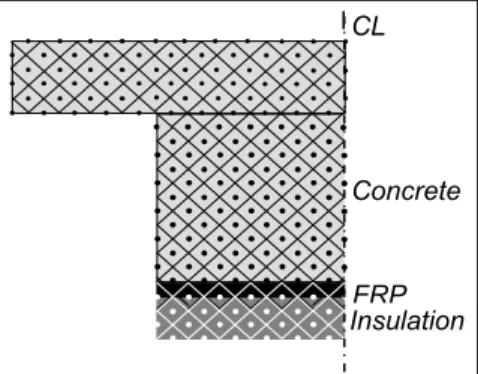
this model was not available for modification for this program’s purposes. Thus, a model was created to allow modeling of the temperature distribution within an FRP-strengthened and insulated concrete beam-slab assembly. The two-dimensional heat transfer model developed during this research program is capable of predicting the temperature distribution within rectangular and tee-shaped reinforced concrete beams during exposure to a standard fire. The model employs the finite difference method, with the bulk of its theory based on equations outlined previously by Lie [21]. The model is capable of analyzing an unstrengthened reinforced concrete beam, as well as simulating the thermal effects of FRP sheets and/or insulation applied to the base and sides of such beams. The model is also capable of simulating the conditions of the test specimens described in this paper; that is, tee-sections with an FRP layer on the soffit and insulation applied to the soffit and sides of the beam, including a portion of the underside of the slab overhang. Enhancing the model’s flexibility is its ability to account for delamination of FRP and insulation; this was useful in comparing the model’s ability to predict data from previous fire tests where FRP and/or insulation delamination was observed during fire. The analysis begins by discretizing a beam’s cross section into nodal points, as shown in Fig. 4, for half of the cross section of a beam-slab assembly strengthened with FRP and protected with a layer of insulation.
Fig. 4. Discretization of beam for heat transfer modelling.
The temperature of the standard fire at the current time step is calculated using an equation provided by ASTM E119 [14]. However, the model can easily be modified to replicate the effects of any type of fire, so long as the temperature-time data is known. A thermal equilibrium equation is applied to each node in the section, and the current nodal temperature is determined based on the temperature and thermal properties of the surrounding nodes during the previous time step. For example, the thermal equilibrium equation for any element, m, along the exterior of the concrete beam at time step j+1 is:
(
)
(
)
[
]
(
) ( ) ( ) ( )
(
)
(
)
(
)
+ ⋅(
⋅)
(
−)
⎥⎦⎤ ⎭ ⎬ ⎫ ⎩ ⎨ ⎧ + − + ⋅ ⋅ ⋅ ⋅ ⋅ + − ⋅ + ⎢ ⎢ ⎣ ⎡ + − ⋅ + ⋅ ⋅ ⋅ ⋅ + ⋅ + = + 25 . 1 4 4 2 1 2 1 . 9035 273 273 2 2 2 2 ambient j m j m j f c f j m j r j m j r j m j q j m j q j m w w j m c c j m j m T T l T T l T T k k T T k k l c c t T T ∆ ∆ ε ε σ ∆ φ ρ ρ ∆ (1) Concrete FRP Insulation CLThe second last term in the above equation describes radiative heat transfer with the fire, and is only applied to those elements which are exposed directly to fire. The last term of the equation describes the change in temperature due to convection heat transfer, and is only used for those elements along unexposed surfaces. The effects of moisture evaporation are included in the analysis by assuming that when the temperature in a node reaches 100ºC, all of the heat transferred to that node is used to evaporate water. During evaporation, the temperature in the node is assumed to be constant at 100ºC, and the temperature rises again only when the moisture has completely evaporated. The effects of moisture migration away from the heat source, which are thought to be significant in accurately predicting temperatures near 100°C, are not currently included. In the derivation of the heat transfer equations, the analysis is performed on a unit length of the beam cross section. This implies that the entire length of the beam experiences identical fire exposure conditions; end effects are ignored.
Validation
Figure 5 provides a comparison between recorded temperature data from the fire tests discussed previously and model predictions. Figure 5a shows that the model underestimated the temperature at the FRP/concrete location of Beam 1 throughout the fire test, but that this difference reduced as the test progressed. Experimental data show that the Tg of the epoxy was exceeded at about 35 minutes, while the model predicts this occurrence at 43 minutes. While the model prediction is unconservative, the time at which the epoxy Tg is exceeded is likely not a valid indicator of FRP-strengthened members’ performance, as discussed previously. Figure 5b shows that the model predicted the temperature of the steel reinforcement in the web of Beam 2 satisfactorily, with a maximum difference of only 25ºC.
It is clear that the model provides only approximate temperature predictions around the FRP layer. This is likely due in part to the sensitivity of the FRP temperature to localized cracking in the VG insulation layer, which is a phenomenon that should somehow be accounted for in future modelling scenarios, perhaps with an artificial increase of the thermal conductivity of the material, or by consideration of thermal effects and moisture migration in three dimensions as opposed to two. Overall, the model predicts temperatures at various locations throughout the beam-slab assembly satisfactorily. This is notable considering the probable slight variation in VG thickness along the beam span, the potential for movement of installed thermocouples from their design locations during fabrication, the likelihood that the concrete’s moisture content varies throughout the section, and the exclusion of moisture movement effects from the modelling process. Finally, it is important to note that since only two full-scale tests were completed in this programme, model validation is based on limited data. Further model validation will be performed in future phases of this research study as relevant specimens data become available.
Fig. 5 (a) Predicted versus measured temperatures at FRP/concrete interface – Beam 1. (b) Predicted versus measured temperatures of steel rebar – Beam 2.
It is clear that the model provides only approximate temperature predictions around the FRP layer. This is likely due in part to the sensitivity of the FRP temperature to localized cracking in the VG insulation layer, which is a phenomenon that should somehow be accounted for in future modelling scenarios, perhaps with an artificial increase of the thermal conductivity of the material, or by consideration of thermal effects and moisture migration in three dimensions as opposed to two. Overall, the model predicts temperatures at various locations throughout the beam-slab assembly satisfactorily. This is notable considering the probable slight variation in VG thickness along the beam span, the potential for movement of installed thermocouples from their design locations during fabrication, the likelihood that the concrete’s moisture content varies throughout the section, and the exclusion of moisture movement effects from the modelling process. CONCLUSIONS
The following conclusions can be made based on the experimental studies and numerical analyses described herein:
• FRP-strengthened and insulated beam-slab assemblies with 25 mm and 38 mm of Tyfo® VG insulation can achieve four-hour fire endurance ratings, as defined by ASTM E119;
• The insulation system evaluated in this research program appears to have effectively protected the FRP strengthening systems from heat penetration. A thickness of 38 mm of insulation maintained the average FRP temperature below the matrix Tg for 54 minutes. In addition, the insulation system maintained low temperatures in the reinforced concrete beams such that the structural elements did not fail under service load levels during fire. • The two-dimensional thermal model described herein is capable of predicting temperatures within the concrete of FRP-strengthened concrete beams with sufficient accuracy to allow for fire endurance predictions. Further extension of the model will be required to precisely model the thermal behaviour at the FRP layer, and
• To enhance the fire endurance of FRP-strengthened concrete members, thermal conductivity, specific heat and application configuration of the insulation layer are key.
Time [minutes] 0 60 120 180 240 300 T e mpe ratur e [º C] 0 200 400 600 800 Model Prediction Measured Time [minutes] 0 60 120 180 240 300 T e mp er at u re [º C] 0 100 200 300 400 500 600 Measured Model Prediction (a) (b)
ACKNOWLEDGEMENT
The authors are members of the Intelligent Sensing for Innovative Structures Network (ISIS Canada) and wish to acknowledge the support of the Networks of Centres of Excellence Program of the Government of Canada and the Natural Sciences and Engineering Research Council. The authors would also like to acknowledge the National Research Council of Canada, Fyfe Company LLC, and Watson Bowman Acme Corporation.
REFERENCES
[1] Ballinger, C., Maeda, T., and Hoshijima, T., “Strengthening of Reinforced Concrete Chimneys, Columns and Beams with Carbon Fiber Reinforced Plastics,” Fiber-Reinforced-Plastic (FRP) Reinforcement for Concrete
Structures: Properties and Applications, Nanni A. (ed.), Elsevier Science
Publishers B.V., 1993, pp. 55-86.
[2] Challal, O., and Shahawy, M., “Performance of Fiber-Reinofrced Polymer-Wrapped Reinforced Concrete Column under Combined Axial-Flexural Loading,” ACI Structural Journal, 97(4), 2000, pp. 659-668.
[3] Fukuyama, H., “FRP Composites in Japan,” Concrete International, American Concrete Institute, 21(10), 1999, pp. 29-32.
[4] Saadatmanesh, H., Ehsani, M., and Jin, L., “Repair of Earthquake-Damaged RC Columns with FRP Wraps,” ACI Structural Journal, 94(2), 1997, pp. 206-215. [5] Grace, N.F., Soliman, A.K., Abdel-Sayed, G., and Saleh, K.R., “Strengthening
of Continuous Beams Using Fiber Reinforced Polymer Laminates,” Fourth
International Symposium on Fiber Reinforced Polymer Reinforcement for Reinforced Concrete Structures, Dolan, C.W., Rizkalla, S.H., and Nanni, A.,
(eds.), American Concrete Institute, Detroit, Michigan, SP188-57, 1999, pp. 647-658.
[6] Tadros, G., McWhinnie, K, and Kroman, J., “Deck Strengthening for Country Hills Bridge in Canada,” Fourth International Symposium on Fiber Reinforced
Polymer Reinforcement for Reinforced Concrete Structures, Dolan, C.W.,
Rizkalla, S.H., and Nanni, A., (eds.), SP188-41, 1999, pp. 455-466.
[7] Bank, L.C., “Properties of FRP Reinforcements for Concrete,”
Fibre-Reinforced-Plastic (FRP) Reinforcements for Concrete Structures: Properties and Applications, Elsevier Science Publishers B.V., 1993, pp. 59-86.
[8] Blontrock, H., Taerwe, L., and Matthys, S., “Properties of Fiber Reinforced Plastics at Elevated Temperatures with Regard to Fire Resistance of Reinforced Concrete Members,” Fourth International Symposium on Fiber Reinforced
Polymer Reinforcement for Reinforced Concrete Structures, Dolan, C.W.,
Rizkalla, S.H., Nanni, A., eds., American Concrete Institute, Detroit, Michigan, SP188-5, 1999, pp. 43-54.
[9] ACI, ACI 440.2R-02: Guide for the Design and Construction of Externally
Bonded FRP Systems for Strengthening Concrete Structures, American
[10] Apicella, F., and Imbrogno, M., “Fire Performance of CFRP-Composites Used for Repairing and Strengthening Concrete,” Proceedings of the Fifth ASCE
Materials Engineering Congress, Bank L.C., ed., ASCE, Cincinnati, Ohio,
1999, pp. 260-266.
[11] Wang, Y.C., Wong, P.M.H., and Kodur, V.K.R., “Mechanical Properties of Fibre Reinforced Polymer Reinforcing Bars at Elevated Temperatures,”
SFPE/ASCE Specialty Conference: Designing Structures for Fire, Baltimore,
MD, 2003, pp. 183-192.
[12] Bisby, L.A., "Fire Behaviour of FRP Reinforced or Confined Concrete,"
Doctoral Thesis, Department of Civil Engineering, Queen's University,
Kingston, Ontario, Canada, 2003, pp. 372.
[13] Williams, B.K., Fire Performance of FRP-Strengthened Reinforced Concrete
Flexural Members, Doctoral thesis, Department of Civil Engineering, Queen’s
University at Kingston, Canada, 2004, pp. 389.
[14] ASTM, E 119: Standard Test Methods for Fire Tests of Building Construction
and Materials, 2002, West Conshohocken, PA.
[15] Deuring, M. “Brandversuche an Nachtraglich Verstarkten Tragern aus Beton,”
Research Report EMPA No. 148’795, Swiss Federal Laboratories for Materials
Testing and Research, Dubendorf, Switzerland, 1994.
[16] Blontrock, H., Taerwe, L., Vandevelde, P., “Fire Tests on Concrete Beams Strengthened with Fibre Composite Laminates,” Third Ph.D. Symposium, Vienna, Austria, 2000, pp. 10.
[17] Bisby, L.A., Green, M.F., and Kodur, V.K.R., “Fire Endurance of FRP-confiend Concrete: Test Results and Model Validation,” accepted, ACI Structural
Journal, 2004.
[18] Gustaferro, A.H., “Temperature Criteria at Failure,” American Society for
Testing and Materials Symposium on Fire Test Performance, Denver, Colorado,
1969, pp. 68-84.
[19] CAN/ULC, “S101-89: Standard Methods of Fire Endurance Tests of Building Construction and Materials,” Underwriters’ Laboratories of Canada, Scarborough, Ontario, 1989, pp. 49.
[20] Alfawakhiri, F.; Kodur, V.K.R., and Frater, G., “Temperature Field Modeling of the First Cardington Test,” Third International Workshop on Structures in Fire, IRC-NRC, Ottawa, Canada, 2004, pp. 59-69.
[21] Lie, T.T., Structural Fire Protection, ASCE Committee on Fire Protection, Structural Division, American Society of Civil Engineers, 1992, pp. 241.
![Fig. 1. Variation in strength with temperature for various carbon Fibre Reinforced Polymers [12,13]](https://thumb-eu.123doks.com/thumbv2/123doknet/14182670.476578/5.918.237.685.244.533/variation-strength-temperature-various-carbon-fibre-reinforced-polymers.webp)