Publisher’s version / Version de l'éditeur:
Vous avez des questions? Nous pouvons vous aider. Pour communiquer directement avec un auteur, consultez la première page de la revue dans laquelle son article a été publié afin de trouver ses coordonnées. Si vous n’arrivez pas à les repérer, communiquez avec nous à [email protected].
Questions? Contact the NRC Publications Archive team at
[email protected]. If you wish to email the authors directly, please see the first page of the publication for their contact information.
https://publications-cnrc.canada.ca/fra/droits
L’accès à ce site Web et l’utilisation de son contenu sont assujettis aux conditions présentées dans le site
LISEZ CES CONDITIONS ATTENTIVEMENT AVANT D’UTILISER CE SITE WEB.
Paper (National Research Council of Canada. Division of Building Research); no.
DBR-P-698, 1976-05
READ THESE TERMS AND CONDITIONS CAREFULLY BEFORE USING THIS WEBSITE. https://nrc-publications.canada.ca/eng/copyright
NRC Publications Archive Record / Notice des Archives des publications du CNRC :
https://nrc-publications.canada.ca/eng/view/object/?id=65fc1b7a-1dfb-44b5-83e0-7c38e073e4fc https://publications-cnrc.canada.ca/fra/voir/objet/?id=65fc1b7a-1dfb-44b5-83e0-7c38e073e4fc
NRC Publications Archive
Archives des publications du CNRC
This publication could be one of several versions: author’s original, accepted manuscript or the publisher’s version. / La version de cette publication peut être l’une des suivantes : la version prépublication de l’auteur, la version acceptée du manuscrit ou la version de l’éditeur.
For the publisher’s version, please access the DOI link below./ Pour consulter la version de l’éditeur, utilisez le lien DOI ci-dessous.
https://doi.org/10.4224/40001761
Access and use of this website and the material on it are subject to the Terms and Conditions set forth at
Design of buildings for fire safety
NATIONAL RESEARCH COUNCIL
OF
CANADA CONSEIL NATIONAL DE RECHERCHES DU CANADADesign
of
Buildings
for Fire
Safety
Ser TKI N21d no.
698
c . 2 - Price 26 cents Reprinted from FIRE TECHNOLOGYVol. 12, Nos. 2 and 3 M a y and August 1976
DBR Paper No. 698 Divieion of Building Reaearch
SOMMAIRE
L a
m6thodee habituelles de protection contre I'incendie sonte-Qee ii la lumi+re des p r o m Acente de la science dea
incendies, et dee erreurs courantes en matihre de proteetion c o n k l'incendie ~ o n t miaes en Bvidence. L'auteur montre que le cofit de la protection contre I'incendie pourrait Btre dduit
consid6rablement per un simple choix dm dimensions dea compartiments, &out des fen6tree. D'autres rnaures, cher- chant
B locaber
l'incendie de facon efficace, sont Btudik.L'auteur d6crit en detail deux nouvelIes techniques complbtes de &curit$ incendie, la premikre appellse "syst&me d'isolation d'inmndie," la aeconde "ssystkme de drainage d'incendie."
On souKgne l'importance de tenir compte de las6mrit.6 in-
FIRE TECHNOLOGY
Design of Buildings for
Fire Safety
-
Part
I
T. Z.
HARMATHYFire
Research SectionDivision of Building Researclt
National Research Council of Canuda
Conventional fire protection practices are examined in the light of recent advances in fire science, and fallacies of the present fire pro- tection philosophy are pointed out.
A
LTHOUGH the understanding of the basic characteristics of building fires has improved substantially during the past decade, it is doubtful whether the solution to fire safety is any closer today than it was ten years ago. Advances in fire science seem to have been consistently outpaced by the emergence of newer problems that tend to make iire potentially more dangerous than ever before. The increasing popularity of high-rise build- ings, the use of large, undivided areas in commercial and office buildings or maisonettes in apartment buildings, and the introduction of a multitude of plastics to replace wood or metal both in furniture and in building com- ponents are only a few examples of the problems with which today's building officials have to cope.Conventional solutions, which were believed to serve the objective of fire safety reasonably well ten years ago, have become ineffective. I t appears now that instead of trying to adapt these conventional solutions to new, changed conditions, it would be more advantageous to take a new look at the whole problem area and develop a new system of defense against fire starting from basic principles.
C O N V E N T I O N A L F I R E P R O T E C T I O N P H I L O S O P H Y
The present fire protection practices were developed a t the beginning
of this century. Their most fundamental feature is the concept that
Nol-tc: Ilr. tlarmnthv presented this aper at the Second International Fire Pro- taction Ei~~ilreeril~y ~nsdbute held at the Lniversity of Maryland, April 27 to May 9, ltP7B.
Cop~rlpht' 1976, NATIONAL FIRE PROTECTION ASSOCIATION, 470 ATLANTIC AVE., BOSTON. MASS. 02210 Pdnhd In U.S.A.
96 Fire Technology the spread of fire can be effectively checked by subdividing the building into "fie resistant compartments," in other words, spaces created by the use of boundary elements (walls, floor, ceiling, etc.) with "fire endurance ratings" ("fie ratings," for short) not less than the minimum prescribed for the type of building by a building code.
The fire endurance rating of the boundary elements is determined with the aid of a standard fire
test.
In North America, ASTM MethodE
119 specifies how thetest
is to be conducted and how to interpret the test findings.In
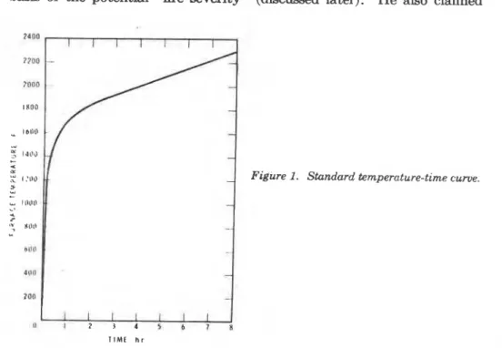
a standard fne k t , a representative sample of a compartment element is e x p d on one side ( w d s , fl00r8, ceilings, beams) or on allsides (columns) te the hat of a tmt furnace, The temperature of the
&ace must follow a preamibed unique temperature-time curve (Figure
I ) , believed originally to reproduce the temperature history of a fully de- veloped compartment
fm.
The length of the expusme to the testf
k
is the perid for which f i e endurance rating (expressed in hours, K,
1, 1 %,
etc.) ia desired. If the s p m h e n element witbtands the simulated h ex-posure for %, 1,
134,
etc. hours without major structural failure and sub- stantial heat transmission, it is "rated" as a %-, I-, 1%-hour, etc. fire re- sistant element.Although the bases on which the required fire endurance ratings are prescribed are not clearly recognizable, the underlying concept unquestion- ably rests on the pioneer work by 1ngberg.l He suggested, more than forty years ago, that the fire endurance requirements be determined on the basis of the potential "fire severity" (discussed later). He also claimed
?
Building Design 97that the fire severity was uniquely related to the specific fire load (weight of
1
combustible materials per unit floor area) characteristic of the occupancyi
~onsidered.~ Thus, his suggestion was equivalent to advocating that theI "fire severity" be judged and the iire endurance ratings prescribed on the basis of characteristic fire loads.
Following this brief survey, it is possible now to recognize two p a - tulates on which the present fire protection philosophy is founded. One is related to the nature of fire, the other to the mechanisms of fire spread.
With respect to the nature of fire, i t is assumed, adopting Ingberg's concept, that the severity of compartment fires depends solely on the amount of combustibles present, more exactly, on the specific fire load. With respect to the mechanisms of fire spread, the method of conducting and evaluating fire endurance tests implies the claim that spread occurs either by structural failure of a boundary element followed by pene- tration of the flames into the neighboring spaces, or by excessive heat con- duction through a boundary element followed by ignition of combustibles in an adjacent compartment.
I n the following sections i t will be shown that both postulates are inaccurate; therefore, the fire safety provided by the fire resistant com- partmentation of buildings is largely illusory.
S E V E R I T Y O F C O M P A R T M E N T F I R E S The fallacy of the concept that the severity of compartment fires de- pends solely on the specific fire load has been known for a t least fifteen years. To enable one to identify the true parameters of fire severity, a somewhat simplified picture of what happens in a burning compartment will be presented in this section. The discussion is based on hundreds of small-scale and full-scale compartment burnout tests conducted by Kawagoe," Gross and R o b e r t s ~ n , ~ Butcher and coworker^,^. and many others, and on this author's theoretical interpretation of these tests,l which in turli, evolved from the excellent theoretical studies performed by Kawagoe,* Thomas et Magnusson and Thelandersson,lo and others. Two introductory remarks seem appropriate: (1) Some of the formulas t.o be presented have been based on the results of burnout tests employing only cellulosic mat.erials (wood, paper, etc.) as fuel. They should be used with caution whenever the fire load consists of substantial amounts of plnsl.ics. (2) Compart,ment fires are extremely complex processes involving, in rttidil.ion l.o hundreds of identifiable variables, a host of incidental vari- cil)lcw: cSc~nsequent lv. t,l~ey are poorly reproducible. I t is not surprising, l.lictrcfort\. I.hal sulwl.anl.ia1 differences exist in the approaches various
' I 'l'htr t\xpuctcd ~ircignilude of the specific fire load may be judged from data collected iu I*:11~ln1ld t~ fvw YHLIPM a ~ o . ~ The mean fire load in modern office buildings is 4.1 Ib/ft2, land i l l !I5 ~)t*rct)~it of' rooms, it is less than 12.0 Ib/ft.? In storage rooms it may be 25 Il~/ft' or higher.
98 Fire Technology authors took in modeling these fires. Yet the main conclusions arrived at, albeit in different ways, show an agreement that should be viewed as remarkably good in relation to the reproducibility of the phenomena.
It can be understood without any deeper insight into the problem that the destructive potential of a fire in an average compartment is determined mainly by two factors - the rate of burning of the com- bustible materials and the rate of convective heat loss through broken windows and open doors. Both of these factors depend just as much on the rate of flow of air into the compartment, i.e., on the ventilation, as on the lire load.
If the doors remain closed and the compartment receives air only through broken windows, the mass flow rate of air can be calculated from the window sizes.
U. = 230 Aw
dhw
(1)The rate of burning of compartment fires (i.e., the thermal decom- position of the combustible materials and the subsequent combustion of the decomposition products) depends primarily on the flow rate of air and on the free surface area of the combustible materials. The latter can be expressed in
terms
of the s p d c surface area of the combustibles and the fire load as follows:Af =
( b G =
(bFAp (2)For conventional furniture 0.55
<
(p<
0.90.The nature of the fire depends on whether the ratio U,/Af is lower or higher than a "critical" value; about 28 lb/ft2 hr. At lower values of this ratio, the rate of burning during the "fully developed" period of firec is determined by the rate of air flow;
the
fire is "ventilation controlled." At higher values, on the other hand, the rate of burning becomes roughly proportional to the free surface area of the combustible materials; the fire is "fuel-surface controlled."By utilizing Equation 2, the following equation can be written for the "critical airflow," that is for the flow rate of air a t which, with increasing ventilation, the fire becomes fuel-surface controlled:
(Ua) c, = 28 (P FAF (3)
I t seems convenient to introduce an "airflow factor," f , and with it write the mass flow rate of air as
U. = .$ (U.),, = 28 (p F A F ~ (4)
'See nomenclature at the end of+the paper.
' 'I'he discuusion presented in this section is a summary of the results developed in Reference 7. The "fully develo ed" period of the fire is the period between thf, "flash- over nnd the end of vigorous B)aming combustion. It is followed by a "deca period d u r i u ~ which the combustion of the remaining solid decomposition products gharcoal) IS completed.
Building Design 99
Obviously, if U, = (U.),,, the airflow fador is 1, and
the fire is ventilation controlled if [
<
1 (5) the fire is fuel-surface controlled if [2
1 (6) A multitude of experimental data revealed that the following equations satisfactorily describe the rate of burning of compartment fires during the fully developed period:i f & < l R = 0.163 U, (7)
i f & 2 1
R
= 4.574, = 4.67 cp FAp (8) In the second of these equations, Equation 2 ha^ been utilized. The mass flow rate of the g88eous products can now be obtained asThe rate of heat evolution during the period of fully developed fire can be expressed as
Q
=R
(0.932/3AHv+
0.068AHc) (10)where B is the fraction of heat released by the combustion of the volatile decomposition products inside the compartment. I t is a function of the flow rate of air, the free surface area of the combustible materials, and the height of the compartment.
Using an average value for the speciiic surface of the combustible materials, cp
"
0.65 ft2/lb, Equations 7 and 8 can be rewritten in the following forms:These equations are plotted in solid line in Figure 2.
The duration of the fully developed period of fire can be expressed asd
7 = 0.932 G / R (11)
Thus, with the aid of Equations 7, 8 and 4,
i f ( < l 7 = 5.72FAp/Ua = 0.204/cp[ (12)
or, assuming that (F
"
0.65, one obtains- ---
100 Fire Technology
I I I I 1 I I I
A I R F L O W R A T E P E R W E I G H T O f C O M B U S T I B L E S U a i G h r - I
F i g u ~ 2. Variation of rate of burning and fire duration with ventilation (approximate relatwns).
u a
if-
2
18.2G
The last two equations are also plotted (in dashed lines) in Figure 2. I t is extremely important to no& that the duration of the fully de- veloped period of fuel-surface controlled fires is independent of the fire load and very short, typically 19 min (0.314 hr).
I t may be useful to rewrite Equation 12, after combining it with Equa- tion l , in
a
form that shows the dependence of the duration of fully de- veloped fires on the ratio A w / A F in the regime of ventilation control:I t can usually be assumed that F 5= 5 lb/ft2 (which value is slightly higher Itla11 the average for residential and office occupancies), and h w = 5 ft. For modern buildings Aw/AF
>
0.1, and thus 7<
0.55 hr. For older buildings An/Ap may be as low as 0.05; therefore, T may rise to 1.1 hr.?'lie following conclusion can now 1 ~ 3 drawn. If a fire occurs in a com- p~rtlnent equipped with windows and t.he compartment contains only the usual fur~~iture characteristic of residential and office occupancies, it is very unlikely that the period of fuHy developed fire could be much longer than
Building Design 101 generally be regarded as indications of the spread of fire beyond the place of origin. The concept of requiring fire endurance ratings much longer than 1
hr with the purpose of preventing the spread of fire t o the neighboring compartments is, therefore, of highly dubious value.
With the aid of the introduced equations or the curves in Figure 2,
it is already possible to draw a t least some qualitative conclusions con- cerning the average fire temperature. At first glance one may think that the maximum temperatures develop a t the "critical point" (i.e., where t = 1 or U,/G = 18.2) where the rate of burning first reaches the highest level, but the flow of fresh air into the compartment is still relatively low. In reality, with increasing rate of burning, the flame length also increases and a larger portion of the chemical energy may be released outside the windows. For this reason, maximum temperatures often occur a t some intermediate airflow rates within the ventilation controlled (i.e., low ventilation) regime.
Figure 3 shows, for a specific case, the variation of the average tem- perature of fully developed fires with increasing rate of airflow (i.e., in- creasing window areas) a t three different specific fire loads: 12.4, 6.2 and 3.1 lb/ft.2 (This information relates t o a compartment 25 f t by 12 ft, 9.5 ft high (7.62 m by 3.66 m, 2.90 m high), and lined with concrete ver- miculite plaster.) Although the curves have been obtained by c a l c ~ l a t i o n , ~ they present a satisfactory picture of the results obtained by e~periments.~ * Arrows indicate critical airflow rates. Clearly, the maximum fire tempera- tures occur a t relatively low ventilations. This fact explains why poorly ventilated fires, such as ship, basement, and theatre fires, are the most destructive ones.
The conclusion reached so far is that well-ventilated fires, i.e., fuel- surface controlled fires, not only burn a t lower temperatures (in general), but also are very short. The common belief that compartment fires are either short and hot or long and relatively cool is, therefore, completely wrong.
The expression "fire severity" has already been used several times but has not been defined. The reason is that it is, in fact, d s c u l t to define in simple terms. Instinctively it is felt that the fire temperature and fire duration both have something t o do with fire severity. These two parameters are, however, not sufficient to characterize the destructive potent.ia1 of fire. To understand the reason, imagine that experimental fires are set in two rooms Ihat contain the same amount of combustibles and are identical in every respect, except that one room is lined with poor, the other with good, noncombustible insulating materials. Obviously, the tempera- ture in the room lined with good insulation will climb higher, and thus the fire will appear to be more severe than in the other room. Yet, because of
---
'The formula applicable to the calculation of the average fire temperature is given later in this section.
Ir
102 Fire Technology
the lesser penetration of heat into the boundary elements, structural damage is less likely to occur.
Clearly, the rate of heat penetration also has some role to play in the destructive potential of fie. To take this fact into account, an ad- ditional parameter, termed "effective heat flux," has been introduced to characterize fire severity.
In summary, the severity (or destructive potential) of a fire can be judged from the valuee of the following three parameters:
the duration of fully developed fire, 7 ;
e the average temperature of the gases in the compartment during the perid of fully developed fire, To; and
a the effective heat flux, i.e., the heat flux that penetrates the boundary elements, also averaged for the period of fully developed fire, qs.
Equations have already been presented for calculating the first of these panmeters (Equations 12 and 13). Finding the values of To and qa consists of a trial-and-error solution of the following two equations:
t
q=[*+[n+F(F)q
0 . 9 ~ (14)q* = --
'
[
Q
-
U#,
(tT,-
T,)-
aAr (To4 - T,4)At
]
(15,The first of these equations has been derived from an expression
describing the heat flow through the compartmeht boundaries, and the \
second, from the overall heat balance for the compartment.
In a later section the value of the,temperature of the hot gases depart- 4
ing from the compartment will also be needed. This temperature can be expressed approximately with the aid of a temperature correction factor as
I
I
Td
= (To (16) If
L
The variation of the effective heat flux with increasing rate of air-
flow is shown in Figure 4 for the specific case discussed in connection with I
Figure 3. Again, the critical airflow ratea are indicated by arrows. From the point of view of intensity of h k t penetration into the boundary ele- ments of the compartment, the borderline between ventilation and fuel- surface controlled fires seems to represent the most adverse conditions.
M E C H A N I S M S O F F I R E S P R E A D
While assuming that the severity of compartment fires depends solely on the fire load is, in itself, grmly misleading, the second postulate of the conventional fire protection philcwophy, namely that fire spreads as a
result of heat c011~1uction through, or structural failure of, the compartment 4 1
I
Building Design
2250
5 10 15
A I R F L O W U, ! b l s e c
Figure 3. Typical relation between auemge fire temperature and v e n u t w n (anvws indicate critical airflow rates).
A I R F L O W U, l b l s e c
Fivure 4. Typical relation between effective heat flux and ventilation (arrows indicate
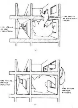
Figure 5. Mecknisrns of fire spread: ( a ) as~medmechanzams, (b) actual mechanisms.
v
104 Fire Technology
boundaries, gives a completely distorted picture to the layman.
It can be
easily proven that, if fire could spread only by these two mechanisms, more than 90 percent of all compartment fires would die out in leas than an hour without cawing major structural damage.The two mechanisms of fire spread, as implied by the conventional fire protection philmophy, are illustrated in Figure 5a. The fire is shown to have spread from the room of origin to the corridor by heat conduction through a wall, and to the room above because of the structural failure of the ceiling.
1: has been recognized for some time that the spread of flaming com- bustion is primarily a convective-radiant process. As Figure 5b shows, the
flames are driven by pressure differences from one space to another, either i horizontally, mainly through doors left open by the escaping tenants, or
vertically through ducts, shafts, openings in ceilings, and by flames issuing from windows then jumping to the floor above. The spread of fire, in other
words, ignition by the advancing &pea, occurs by a combination of direct I
contact with a combustible material and by irradiation by relatively short- range fluxes emanating from the flames.
Occasionally, fire may also spread by long-range thermal radiation originating from a maas of flames through areas of communication between the space on fire and its envjronment.
Of course, walls, floors, or entire buildings occasionally do collapse in fire. However, in such cases the pollapse usually occurs after the spread of fire to the adjacent spaces, i.e., the collapse is the result and not the cause of the expansion of the fire.
t I I I SPR1)IO BI S I R U C I U R a 1 t l l l U R I 1 i
1
Building Design 105 P R E S S U R E D I S T R I B U T I O N I N
B U I L D I N G S
Since convection has been recognized as the principal mechanism of f i e spread, a short discussion of the causes of convective fire spread, namely the pressure differences that exist between various spaces in the building, is in order.
From the point of view of the problems encountered in designing the appropriate fire safety system, the various building spaces can be classiiied as belonging in one of four groups: (1) rooms; (2) uncompartmented spaces; (3) corridors (for the horizontal movement of people and goods); and (4) shafts (staircases, elevator shafts, etc., for the vertical movement of people and goods). As will shortly be seen, the spaces in Group 4 play a very important part in the pressure distribution in the building. Usually, however, they are not regarded as potential sources of fire.
As a rule, the pressure differences between the various spaces in a building are larger when large differences exist between the temperature of the interior and the outside atmosphere, in other words, during the winter heating season.
The experimental studies of heated multistory buildings by Tamura and Wilsonns '2 indicate that the pressure distribution in various spaces
along the height of the building can be represented approximately by a series of straight lines, as shown in Figure 6. (In reality, the curves for rooms, uncompartmented spaces and corridors show slight discontinuities a t the ceiling of each story.) They can be described by the following equation: j
where pa, the preasure of the outside atmosphere, is
provided that its value a t the z = 0 level is taken as reference pressure level.
If x = 0, Equation 17 obviously describes the pressure of the outside atmosphere. When x = 1, the variation of the pressure in the vertical shafts of the building is obtained. For other spaces 0
< x
<
1; its actual value depends both on the "airtightness" of the building and on the resistance to airflow between the respective space and the nearest shaft. lJsually x 1- 0.8 for rooms. For uncompartmented spaces and corridors anominal value of x = 0.9 may be used.
r For convei~ittncu. prewures are expremed a s Ib/ft hr.8 To obtain values in inches of water. multiply values in Ib/ft hra by 4.61 X 10-lo.
106 Fire Technology According
to
Equation 17, a t z = b, p = pa, i.e., the pressure in the building is equal to that of the outside atmosphere; therefore, there is no air exchange between the building interior and the outside atmosphere.b is r e f a e d to as the elevation of the neutral pressure plane. For buildings not equipped with a ventilation system, the neutral pressure plane is usually located a t the mid-height of the building, i.e., b
"
H / 2 . Mechanical ventilation generally causes the neutral pressure plane to descend to a lower level.In the upper stories of the building (above the neutral pressure plane), the highest pressures always prevail in the shafts. They drop moderately across each internal obstacle (door, partition) toward the boundaries of the building and produce horizontal airflows from the shafts through the internal obstacles to the exterior walls and finally to the outside atmosphere. Obviously, if fire breaks out on the upper floors of a building, the main direction of the spread of fire will be toward the outside boundaries of the building. If the floors are reasonably fire resistant and the building is equipped with "flame deflectora" (discussed later), the fire will die out on reaching the exterior walls without human intervention. Vertical leakage currents (not discussed here in detail) will, however, result in the amoke contamination of a few stories above the fire room.
Unfortunately, the conditions are not so favorable in the stories below the neutral pressure plane. Here the lowest pressures prevail in the shafta. The general direction of the spread of fire is, therefore, toward the shafts of the building, although thermal radiation may result in unexpected turns. The major problem is, however, not so much the spread of fire as it is the spread of combustion products, which are carried through the shafts by the air currents to the upper floors, and as Tamura and co-workers pointed out,13. l4 cause dangerous conditions there long before the flames
can reach the shafts.
U N C O M P A R I M E N T E D S P A C E S . C O R R I D O R S
Figure 6. Pressure distribution in buildings.
FIRE TECHNOLOGY
Design
of
Buildings
for
Life
Safety
-
Part
N
C
T.
Z.
HARMATHYFire Research Section
Division of Building Research
National Research Council of Canada
This ia a continuation of the author's examination of conventional fire protection practices.
T
HE
FIRST part of this paper discussed conventional f i e protection philosophy. It then took a look a t the severity of compartment fires, mechanisms of fire spread, and pressure distribution in buildings.R E D U C I N G F I R E S E V E R I T Y I N T H E F I R E C E L L
With a clear understanding of the true nature of building firm and the mechanisms of fire spread, it is easy to devise truly effective fire protection
rneasuree. The simplest way of improving fire safety
is
to reduce itsdeetructive potential in the "fire cell" (space on fire) by ensuring that the fire, if it occurs, will
be
fuel-swrface-contr01led. in other words, byueing large window
areas
whenever possible.This
method of protection,which is discu& in more detail in other publications16. 16,
is based on the
previous fincling that the fully developed period of fuel-surface-controlled
firen is only atmut 20 min. Since almost any noncombustible compartment
etemenb is capable of resisting the spread of fire for at least
M
hr, i t h o m e spossi l ~ l e to reg lace fire resistance requirements with ventilation require-
ments. This means that the designer is entil led to decide whether to choose between buildings built with small windows and heavy fire-rated walls and
I
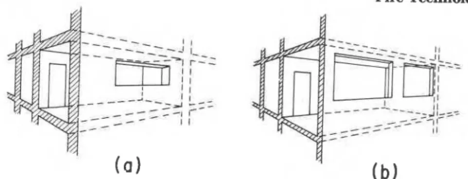
floors, as illustrated in Figure 7a, and buildings with large windows and lighter noneornbustible, non-fire-rated elements, as shown in Figure 7b.OBy combining Equations 1 and 3 a criterion can be derived for the minimum window area that will ensure fuel-surface-controlled burning:
u~evertheless, a few key elemente of a building must be designed to retain structural soundness even after the spread of fire, in other words, to withstand fire exposure from two sides. This aspect of the problem is discussed in a paper "Fire Resistance Versus Fire-Spread Resistance," to be published in the November issue of Fire Tech- nology.
219
C o ~ ~ r l o h l ' 1976. NATIONAL FIRE PROTECTlON ASSOCIATION, 470 ATLANTIC AVE.. BOSTON. MASS. 02210
220 Fire Technology
I
Figure 7. Choices in providing fire safety: (a) by fire-rated compartment boundaries and (b) by large ventilatwn.
The condition that enables the designer to disregard the fke resistance requirements is not too restrictive. For example, if cp
"
0.65, a t a 5 lb/ft2specific fire load (which is slightly higher than the average in residential and office occupancies) and a window height of 5 ft, the total window area must amount to a t least 17.7 percent of the floor area. This figure reduces
to
14.0 per cent for a window height of 8 ft.hAnother way to reduce the destructive potential of fke in the fire cell is to have relatively low ceilings. In this way a larger portion of the flames is forced to burn outside, and thus the heat released inside the compartment will decrease. I t should be realized, of course, that this procedure creates an i n c r m d danger of spread of fire along the facade of the building. (A method of overcoming this danger will be discussed later.) Reducing the fire severity by correctly selecting the compartment and window dimensions is, however, only the first step in the correct design. The designer must take additional steps to prevent the spread of fire from the fire cell to the neighboring spaces. Two methods of achieving this will now be discussed. One will be referred
to
as "fire isolation" method and the other as "fire drainage" method." F I R E I S O L A T I O N " M E T H O D
As
pointed out in connection with Figure 5b, the two main routes of the spread of fire are the doors left open by escaping tenants and the broken windows that permit the flames to climb from story to story along the facade of the building. The essence of the "fire isolation" method is to cut off these routes, and the tools in achieving this are self-closing doors,T h e possibility of achieving fuel-surface-controlled burning can also be expressed in terms of maximum compartment depths. Thus, if the windows are 5 f t high, it can be achieved only if the compartment is not deeper than about 28 ft. If the win- dows are 8 f t high, the maximum pemisib!e d~=+-!: &creases t o 57 ft.
Building Design 221 continuous balconies, open corridors, and a simple device called "flame deflector."
I t
has
long been known that closing devices applied to conventional hinged doors provide excellent protection in fire situations. Several build- ing codes have already made their use mandatory in high-rise * buildings.Unfortunately, hinged doors may present some problems if fire breaks out in one of the lower floors during the winter heating season. After the windows of the fire cell are broken by the fire, it may be difficult or even impossible to open the corridor door because of the large pressure dif- ferences between its two sides.
!
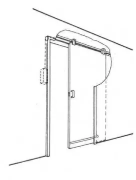
I t would be more practical to use weight-operated, self-closing slidingdoors. If such doors are hung by rollers from a concealed rail and sup- ported by two more rollers near the bottom, as shown in Figure 8, opening
I
them a t any pressure difference would require less force than that required to open a hinged door equipped with a closing device a t no pressure dif-I ference.
Naturally, all self-closing corridor doors, hinged or sliding, must be
I capable of withstanding a compartment burnout, in other words, they must
I
provide a t least a 30 min fire resistance (assuming that the criterion de- fined by Equation 19 is fulfilled), although not necessarily in the sense
I
specified by the fire test standards.I Even though the main function of these self-closing doors is to prevent
I
the spread of flames, they also serve to prevent or, a t least substantiallyI
reduce, the spread of smoke in the building.222 Fire Technology
A systematic investigation conducted in Australia1' confirmed the earlier British findings that 2-ft projections over the windows cannot pre- vent the flames issuing through the windows from curling back and igniting the story above. It was found, however, that projections wider than 3 to 4 f t are effective in keeping the flames away fkom the face of the building and in reducing the radiation hazard from the flames.
Obviously, continuous balconies and open corridors can play a useful part in protecting buildings against massive fires. Unfortunately, their use is rarely considered nowadays even for residential buildings, because they cut down the natural daylight reaching the interior, substantially increase the building costs, and may produce aesthetically undesirable effects.
The "flame deflectors" are simple devices, which, nevertheless, can provide the same degree of protection as continuous balconies and open corridors, a t substantially lower costs and without the aforementioned drawbacks.
As described in a recent note,'" flame deflectors are light metal panels mounted above each window
and
held in a vertical position by a fusible fastening device.T h e
width of these panelsi~ at
least 3 f t 3 in., and their length equal to the width of the window plus about 4 ft. As Figure 9 shows, the deflector fa& down to assume a horizontal position when activated by flames issuing horn the window below. Covered with baked-on enamel, or furnished with bronzed, imprinted mfaces, the deflectors m a y be con- sciousIy applied to the building as decorative elements.Although the fire isolation system does not protect the occupants of
Figure 9.
Building Design 223 the fire cell (except that the sliding doors facilitate their escape from fire), it does protect all other people in the building. Its adoption would substantially diminish the hazard of structural failure of building com- ponents in fire, as well as smoke inhalation by the occupants and reduction of visibility due to smoke. I t would thus enable the designer to dispense with a number of costly measures that are now used to provide fire safety. The resulting savings would more than offset the extra expenditures as- sociated with the use of self-closing doors and flame deflectors, estimated to amount to about 1.5 percent of the building cost.
Of course, in evaluating the financial advantages or disadvantages of a new system, it is impmible to consider other than the capital costs. One cannot foresee how a new design may affecl the insurance premium, or express in dollar value the higher sense of security that would be felt by
the occupants.
With the combined use of self-closing doors and flame deflectors, the fire isolation method is especially suitable for the fire protection of well-compartmented buildings, such as hotels, apartment buildings, and some office buildings. The "fire drainage" method, to be described next, is applicable primarily to poorly compartmented high-rise buildings.
" F I R E D R A I N A G E " M E T H O D
The basic idea behind the fire drainage method is to utilize the energy of the fire itself to render it relatively harmless. The energy of the fire is exploited in three ways: (1) to draw air into the fire cell in quantities that ensure fuel-surface-controlled conditions, i.e., short fire duration and relatively low fire temperature, (2) to keep the pressure in the fire cell below the pressure levels prevailing in the neighboring spaces, and (3) to remove the flames and smoke from the fire cell in a safe and organized manner.
DESCRIPTION
Tlrc technical details of realizing the fire drainage method depend,
1.0 some exLent, on the type of building space to which iL is applied. As discussed earlier, there are four groups into which all building spaces can be divided: (1) rooms'; (2) uncompartmented spaces; (3) corridors; and (4)
shafts. I t was also noted that, from the point of view of designing fire safety measures, oilly the first three groups need to be considered.
Spaces in Groups 1, 2 and 3, equipped with, fire drainage systems, are shown schematically in Figures 10, 11, and 12, respectively.
Figure 10 shows a typical hotel room. The window, 1, plays a very important role in the event of fire and, therefore, its area and construction is part of the design procedure. The "drainage ducts", 2 and 3, extend along
'Itoonm are included in the following discussions for the sake of completeness. How- crvor. ucluil~l~inlr; rooms with fire drainage facilities is advisable only if the building is lclcnted in 11 relatively calm area or the windows face an enclosed yard. If these
224 Fire Technology
Figure 10. Typical room in a building equipped with fire drainage system. 1 -
window, 2 and 3 - drainage ducts, 4 and 5 - access gates.
the entire height of the building. Each room is generally served by two ducts. In turn, each duct serve two tidjacent rooms on every story through openable "access gates," 4 and 5, installed near the ceiling. I n addition, the drainage ducts have "release gates" on the top (not shown). If fire occurs, the windows break and the appropriate access and release gates are opened by the heat of the
fire
(ina
way to be discussed). Air is drawn into the fire cell through the broken windows a t a rate required to produce low fire severity. Owing to the suction created by the column of hot gases in the drainage ducts, the pressure in the fire cell reduces to a level below that in the surrounding spacee, and the f l k e s and smoke "drain" to the outside through the ducts.As will be later discussed, the total cross sectional area of the drainage ducts usually amounts to 1 to 3 percent of the total floor area.
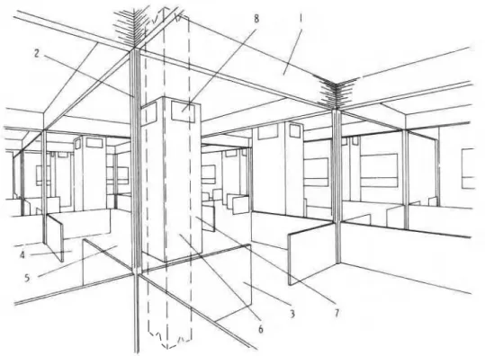
In Figure 11 a large uncompartdented space is shown. The ceiling is divided into many rectangular m& by a series of retracted fold-up
curtains, 1, made of light-gage metal and equipped with weightier bottom pieces. The purpose of these curtains is twofold. First, they restrict the spread of flames and smoke during the growth period of fire when the drainage system is not yet operative, and secondly, when activated by the fire, they slide down in grooves, 2, to fldor skirting boards, 3. In this way they surround the fire, leaving only four openings, 4, properly sized for the controlled ventilation of the fire.
Obviously, even though the occupants have an unobstructed view over practically the entire &ea, the space is, in effect, subdivided into a number of elementary areas; "cells," 5.
I n the figure the drainage ducts, 6, are located a t the center of each elementary area, and can be conveniently combined with the building columns. 7. The ducts extend along the entire height of the building. Each has four access gates, 8, next to the ceiling on every story and release
gates at the top (not shown). Tlle system functions in a way similar to
t hnt described earlier.
I
Building Design -.=
the elementary areas, the designer can arrange to have each duct serve two or four adjacent areas. Such arrangements may allow substantial re- ductions in the total cross-sectional area of the drainage ducts.
Figure 11. Typical undivided space equipped with fire drainage system. 1 - fold-up drop curtain, 2 - curtain grooves, 3 - floor skirting boards, 4 - ventilation control openings, 5 - elementary areas, 6 - drainage duct, 7 - building column, 8 - access gates.
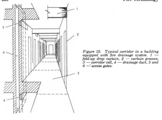
Figure 1 2 shows a corridor, also equipped with fire drainage facilities. Again, fold-up drop curtains, 1, are used with a twofold purpose; to limit the spread of flames and hot gas= while retracted, and t o control the rate of I~urning and the pressure after their activation by heat. To perform t.htse Sunct.ions, they slide down in the provided grooves, 2, to a predeter- mined dista~lcc from the floor, leaving an area available for the inflow of air. The locniion of the curtains determines the area of the corridor "cells,"
3. Each corridor element is served by one drainage duct, 4, and each duct communicates with a numtw of corridor cells located above each other, tlwough heat-activated access gates, 5,6. (The release gates are not shown.)
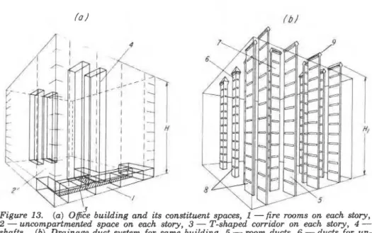
I An eleven-story office building is shown schematically in Figure 13a.
I t has five rooms, 1 , an uncompartmented space, 2, and a T-shaped cor- ridor, 3, on each story, and four shafta, 4. (Washrooms normally contain
I very little combustible material and, therefore, need not be considered in
I
226 Fire Technology
Figure 12. Typical corridor in a building equipped with fire. drainage system. I - fold-up drop curtazn, 2 - curtain grooves, 3 -,corridor cell, 4 - drainage duct, 5 and 6
-
access gates.The fire drainage system for the building is shown schematically in Figure 13b. I t consists of six ducts, 5, serving the rooms (five on each story), ten ducts, 6, serving the uncompartmented spaces, and two ducts,
7, serving the corridors. The ducts usually extend above the roof level, so that H I
>
H. There are access gates, 8, on the ducts on each story near the ceiling level, and release gates, 9, a t the top.SIMPLIFYING THE
THERMAL
PROBLEM
As discussed in more detail in Reference 19, the design of a fie drainage system is not sensitive to the input information concerning the character- istics of fire. Because of this fortunate circumstance, the design can be based on a set of nominal (but realistic) data.
The average temperature of the gases in the drainage duct, TD, is one of the basic design data. Although normally some temperature drop along the duct could be expected, there is a strong possibility that this drop will be partly or fully compensated for by the continuing burning of some departing gaseous decomposition products. Since, as long as TD is higher than about 1000" R (540°F), the operation of the fire drainage system seems to depend only slightly on TD and, contrary to expectations, more adverse conditions arise a t higher values,lg a conservative design will result from the assumption that:
Building Design f o l
5 Y -
Figure 13. ( a ) O@ce building and its constituent spaces, 1 -fire rooms on each story, 2 - uncompartmented space on each story, 3 - T-shaped corridor on each story, 4 - shafts. (b) Drainage duct system for same building, 5 - room ducts, 6 - ducts for un- compartmented spaces, 7 - corridor ducts, 8 - access gates, 9 - release gates.
14 to 16. Yet these equations contain variables that are not readily
available to the designer. I t is necessary, therefore, to simplify the cal-
culation procedure and eliminate from Equations 14 and 15 a number of
variables by replacing them with constant values or by the use of approxi- mate expreasions. The simplification3 has resulted in a set of equations
that can be used to calculate
T d
as a function of the air flow factor, t,and the floor area of the fire cell. The calculations have been performed for the three types of building spaces discussed, i.e., rooms, uncompartmented
spaces, and corridors, and the results are presented graphically in Figure 14.
Omitting the analysis of the general conditions, discussion of the de- sign procedure will be restricted to that case in which the fire cell can develop communication with one "dominant," "horizontal" "environment" only.
The word "environment" is used here in a s p d c sense. Each space
that has a different temperature or pressure or both, and can communicate
wit 11 t,he fire cell through one or more openings or passages, is regarded as a separate environment. In a building equipped with a fire drainage system any fire cell has a t least two environments, one of which, namely the out-
aide atmosphere a t a pressure prevailing a t the release gates (see Figure
In[)), is always the s a n e mespective of the location of the fire cell. The
other environment or envirolunentu, lie beside the fire cell and, therefore,
will be rrbferred t,o as "horizontal" environments. Two or more horizontal
-
228 Fire Technology
environments may be present. For example, a burning room communicates in a major way with the outside atmosphere (at a pressure prevailing a t the elevation of the room) through broken windows. In addition, it also com- municates with the corridor, either in a major way through an open door or in a minor way through gaps around a closed door. If the door is open, the room (fire cell) has two "dominant7' horizontal environments. I t is part of the design procedure to ensure, by the use of special devices (self- closing doors in the given example), that the fire cell will communicate only with one dominant horizontal environment.
As discussed earlier, during the winter heating season the pressure distribution in a building is such that there is an increased danger for the spread of fire and smoke to other stories if fire breaks out in a story below the midheight of the building. This danger is especially acute in the case of ground floor fires, because, according to Figure 6, it is the ground floor level (i.e., z = h / 2 ) where the largest adverse pressure differences between
the various building spaces ark!. It is necessary, therefore, that the
'
design of
the f m
drainage system be b e d on conditions prevailing on the ground floor during the winter. If designed for thme conditions, the system will operate satisfactorily on most other stories and in any season ofthe
year.If fire breaks out, the fire cell will receive air from its dominant hori- zontal environment. The condition of airflow from the dominant horizontal
environment (on the ground floor) to the f i e cell is
j,
< I;,
or, according to Equation 17, +>
I;:
..
Fulfilling t b condition aloneis,
however, rarely auficient.As
discuwed earlier, thefire
cell usually also communicates, even t!lough in a minor way, with one or more eecondary horizontal en-vironmenc~.
The condition of no passage of flames and smoke to a secondyy ho~i- zontal environment is Ij+
I
>,
or I;, 2;I,.
Since, in general, p ,<
p,,both conditions, namely that (1) the fire cell receives air from the dominant
horizontal environment, and (2) the fire and smoke do not enter a secondmy horizontal environment, are satisfied by wlecting the p m u r e level in the
space on fire a s i d =
i.,
in other words by choosingi ,
=;
,.
The fmt step in the daign is to aasign values to j;, and
G1
in sucha WAY M to ea tisfy the foregoing two conditions, To illustrate the procedure, let it be aasumed that the task is to: design the fixe drainage system for a
h g e ur~compartmented space. For a particular cell of this space the
adjoining cells reprment the dominant horizontal environment for which, as
discussed in co~lnection with Figure 6,
i ,
*
0.9.The
design can be baaed on t h e refitriulio~l that any cell on fm must not spill flames into anyaecor~clary horizontal environment, possibly an adjacent elevator shaft, for
wllirlt
I*
= 1. Tllus the deign begins with the se1ection of the followingvalues: x , = 0.9.
i4
( = ;,) = I.It is possible now to calculate the area of communication between the fire cell and the dominant liorizontal environment, Ac, through which air is admitted to the fire. For rooms it is the "effective" window opening
Building Design 229 (to be defined later), for uncompartmented spaces it is the total area of the four openings in the floor skirting boards (see item 4 in Figure l l ) , and for corridors it is the sum of the two areas left open below the activated fold-up drop curtains (see Figure 12).
The area of communication with the dominant horizontal environment plays an important part in the proper functioning of the system, because i t controls both the pressure level in and the rate of airflow to the fire cell.
As discussed earlier, it is desirable that the rate of a d o w be large enough to ensure low f i e temperature and short fire duration, in other words that the burning take place well within the fuel-surface-controlled range of conditions: [
>
1.After assigning a value to t (usually [
*
1.5), and selecting the tem- peratures T,, T,, and T, (corresponding to the winter heating conditions), the following equation can be usedla to calculate Ac:.
T d can now be determined from the T d versus 5 plot in Figure 14. The value of a pressure l m coefficient, a, has yet to be estimated (usually
2
<
a<
5). Then the cross-sectional area of the drainage ducts, AD, canbe calculated as follows:
A ,, usually comes out as 1 to 3 percent of the floor area. Naturally, if each duct is designed to serve two adjacent spaces in a way shown in Figure 10, the loss of useful floor area is only
W
to 1W
percent.Although Ihe values Ac and AD have been obtained for the ground floor level conditions, they usually ensure satisfactory operation of the system even if the fire cell is located on another story. To minimize the pressure losses at the entry of the gaseous products, it is practical to select the tolal area o f t he gates as equal to the crw-sectional area of the ducts.
The designer may now use Equation 4 and the following approximate fornlula :
U , ru 1.163 U,, (23)
if he is int.erested in knowing the rate of airflow in and the rate of flow of gaseous produds out of the fire cell.
The fact, that the described version of the fire drainage system does not rely on the availability of electricity a t the time of fire is undoubtedly
Fire Technology
Figure 14. Temperature of de- parting gaseous products.
a deairaMe feature. Yet, if apecial measures are taken to ensure that
emergency electric power is always available a t the roof level, a forced
drainage version (more exactly: assisted drainage version) of the system can be devised, which may sometimes offer advantages. With the aid of exhaust fans installed a t the top of the drainage ducts, the designer can sub- stantially reduce the duct areas and, a t the same time, acquire a larger degree of freedom with respect
to
the routing of the ducts. This forced drainage version of the systemis
further discussed in Reference 19.I n the case of rooms, Ac is the "effective" window area, i.e., the area
I
that becomes available for the inflow of air after the glass panes are brokenby the fire.k This is the area that controls the rate of airflow into, and the pressure level in the fire cell. More often than not, this area comes out to leas than 10 percent of the floor area of the room, which is regarded by many as the minimum for proper lighting. It seems imperative, there- fore, to provide some additional window surfaces made with panes that ' cannot be dislodged by the fire and are either nonopenable, or are self- closing in the event of fire.
Based on thees coneiderations, two types of glazing must be employed; one that beaks very easily under fire exposure, and another that does not
hmak
or at least remains in place after breaking. According to B.S.CY-153,?"
ordinary annealed glass qualifies for the first type. The standardaho describes some glazinp that qualify for "fire resistance."
T h e reader is reminded that equipping rooms with fire drainage facilities is not recorn- mended in windy areas. See Footnote i.
Building Design 231 Figure 15 shows one of many possible window solutions. The upper and larger section of the window surface is made from fire resistant glass, the lower section from ordinary glass. The latter section is openable in the conventional ways. In addition, the frame containing both sections can be opened with the aid of a combustible rope or girdle. I n case of fire the hot gases accumulating below the ceiling burn away the exposed section of the rope and cause the entire window panel to fall back into the window seat.
As mentioned earlier, it
is
desirable to ensure that the fire cell have only one dominant environment. In the case of rooms, this can be achieved by using self-closing sliding doors, possibly the type discussed earlier (see Figure 8).The walls of the drainage ducts and the access gates must be designed in such a way as to exclude even the slightest possibility of damage by heat transmission in all building spaces located above the fire cell. To achieve this, the designer may choose either (a) to employ a "heat sink" construction, e.g., double-walled light metal ducts and gates, filled with water (with some additives) between the walls, or (b) to insulate the duct walls and access gates, as shown in Figure 16. If the former solution is chosen, the designer must be aware of the problem of pressure buildup in the liquid-filled spaces due to vaporization, and provide means of re- lieving the pressure.
In order to best utilize the space and to minimize the pressure losses a t the entry of the gases, the use of narrow (6 to 12 in. wide) drainage ducts and gates seems to be most advantageous for rooms and corridors
Figure 16. Window, to be
232 Fire Technology
(aee
Figma 10
and 12). For unmmpartmented spaces, ducts of roughly square crm-section are recommended, which, aa Figure 11 shows, m a ybe
combined with the building columns.The activation of the gates shown in Figure 16 doea not depend on
the
availability of electric power at the time ofh.
The access gates, 1, are heldin
the closed position by a low-melting nut, 2. Ifh
breaks out, the nut melts and the gate swing8 open The top reIease gates, 3, are held cloaed by the pull of a low-melting line, 4, running along the entire length of the duct and loaded with a weight, 5. The hot gases, penetrating the duct after the opening of the accees gates,break
the line and deploy the r e l m gates-Again, it is possible to discuss the capital c a t s only. Equipping a building with a fire drainage system would mean savings
in
some respectsand extra expenditures in others. Being a comprehensive defense system
against fire, the
fire
drainage systemis
capable of replacing mtlst of theFigure 16. Fire drainage duct and gates,
1 - access gates, 2 - nut of low melting point alloy, 3 - release gates, 4 - line of low melting point alloy, 5 - weight.
Building Design 233 conventional protection facilities (e.g., fire resistant compartmentation, sprinklering, extra escape routes, smoke control measures, etc.). Dispens- ing with these facilities would undoubtedly result in substantial savings. I t is unlikely, however, that the savings could completely compensate for the extra expenditures associated with (1) the loss of useful floor area, (2) the installation of extra facilities such as drainage ducts and gates, fold-up drop curtains, and (3) the replacement of conventional doors and windows by self-closing varieties. I t is estimated that these extra expendi- tures would be comparable with those of equipping a building with a sprinkler system.
Being comparable in costs and in the quality of protection provided, one may ask why anyone would prefer using fire drainage system instead of sprinklering system. For several reasons: (1) the fire drainage system does not require maintenance; (2) no property damage can result from its mis-
use; (3) its operation does not rely on the availability of water or electricity
a t the time of fire; (4) during fire, it keeps the surrounding areas relatively clean, so that the fire can be closely approached and extinguished even by people not experienced in fire fighting; and (5) with its use the damage is always confined to that done by the fire itself in the fire cell. ( I t is well known that with sprinkler system water damage often exceeds that done by the fire.)
C L O S I N G R E M A R K S
The most important message the author hopes to convey is that the continuing reliance on the effectiveness of fire resistant compartmentation is the main reason for much of the present difIiculty in providing fire safety. I t is possible to devise truly effective fire safety measures, but these must
i
be based on a clear understanding of the characteristics of the fire and of the mechanisms of its spread. The severity of ~otential fires can be reduced, and a t the same time savings realized, simply by proper dimensioning of the compartments. The expansion of the fire can be prevented by cutting off the main routes of spread with t.lle aid of inexpensive devices. Furthermore, even the energy of the fire itself can be exploited in the fight against its spread. Some of t.hwe measures may sound unorthodox a t first hearing, yet, they are onlyI
logical prodi1c:ta of l.lle available knowledge.11 is tbxtrt~nely important. to realize t.hai, fire safety is not something t.o 1,e "tactdt~i on" nSt.er the complei.ion of t.he plans for a building. To be really etlbct.ive t.lle probleni of fire safety must be considered from the 1)egilining of L.lle archit.ectura1 design. Itetll progress toward achieving fire safety ca~luot, come until it is clearly understood that the time when a build- ing was regarded as a passive mass for providing shelter, passed a long time ago. A moden1 building is a machinery of multiple functions. Defense against fire is one of the functions of this machinery.
234 Fire Technology
N O M E N C L A T U R E area, ft2
elevation of neutral pressure plane, f t
constant, = 39.74 lb R/ft3 for air and gaseous products of fire
spedic heat, Btu/lb
R
specific fire load, = G / A F lb/ft2
acceleration due to gravity, = 4.17 X
lo8
ft/hr2total fire load prior to fire, lb
height; without subscript: height of story, ft height of building, ft
height of fire drainage ducts, ft heat of combustion, Btu/lb
thermal conductivity of compartment lining, Btu/ft h r
R
pressure, lb/ft hr2 heat flux, Btu/ft2 hr
rate of heat evolution, Btu/hr
rate of burning during fully developed fire, lb/hr
temperature,
R
(if not otherwise stated)mass flow rate, lb/hr elevation, f t
pressure loss coefficient, dimensionless
fraction of heat released by combustion of volatile decomposition products inside the fire cell, dimensionless
orifice factor due to flow of air through contracted openings
(windows, floor skirting board openings, etc.),
"
0.7 di-mensionless
factor of correction for temperature of gases leaving the fire cell,
1 1.06, dimensionless
thermal diffusivity of compartment lining, ft2/hr airflow factor, dimensio~iless
Stefan-Boltzmann constant, = 0.1713 x Btu/ft2 hr
R4
duration of fully developed fire, hr specific surface of fuel, = A f/G ft2/lb pressure factor, dimensionless
a = of air, of outside atmosphere
a- = of the charring fuel (cellulosic, in general)
#- r = critical
I' = of the route of communication between the fire cell and its
dominant horizontal environment
d = of the gases departing from the fire cell