Publisher’s version / Version de l'éditeur:
Vous avez des questions? Nous pouvons vous aider. Pour communiquer directement avec un auteur, consultez la première page de la revue dans laquelle son article a été publié afin de trouver ses coordonnées. Si vous n’arrivez pas à les repérer, communiquez avec nous à PublicationsArchive-ArchivesPublications@nrc-cnrc.gc.ca.
Questions? Contact the NRC Publications Archive team at
PublicationsArchive-ArchivesPublications@nrc-cnrc.gc.ca. If you wish to email the authors directly, please see the first page of the publication for their contact information.
https://publications-cnrc.canada.ca/fra/droits
L’accès à ce site Web et l’utilisation de son contenu sont assujettis aux conditions présentées dans le site LISEZ CES CONDITIONS ATTENTIVEMENT AVANT D’UTILISER CE SITE WEB.
Internal Report (National Research Council of Canada. Institute for Research in Construction), 1999-08-01
READ THESE TERMS AND CONDITIONS CAREFULLY BEFORE USING THIS WEBSITE.
https://nrc-publications.canada.ca/eng/copyright
NRC Publications Archive Record / Notice des Archives des publications du CNRC :
https://nrc-publications.canada.ca/eng/view/object/?id=2ae3ad5d-3559-4d85-a80c-be7744473c24 https://publications-cnrc.canada.ca/fra/voir/objet/?id=2ae3ad5d-3559-4d85-a80c-be7744473c24
NRC Publications Archive
Archives des publications du CNRC
For the publisher’s version, please access the DOI link below./ Pour consulter la version de l’éditeur, utilisez le lien DOI ci-dessous.
https://doi.org/10.4224/20331349
Access and use of this website and the material on it are subject to the Terms and Conditions set forth at Simulation of Repeated Foot Traffic over Low-Slope Roof Surfaces Liu, K. K. Y.; Booth, R. J.; Lei, W.; Irwin, J. D.
--
-\ National Rbsearch Conseil national
S e r
I*I
Council Canada de recherches Canadano. 8 0 0 I RC
Simulation of Repeated Foot Traffic over
Lo w-Slope Roof Surfaces
by Karen K.Y. Liu, Robert J. Booth, William Lei
and Jayne
D.
Irwin
Internal Report No.
800
Simulation of Repeated Foot Traffic over Low-Slope Roof Surfaces
1. SUMMARY
Repeated foot traffic over conventional roof surfaces was simulated by subjecting different roofing assemblies to cyclic compression testing. A haver-sine compression loading function with a magnitude of 45.4kg and a frequency of 1 Hz was used. Three different plastic foam insulation samples (polyisocyanurate, phenolic and expanded polystyrene) were tested with the loading head (the heel of a work boot) positioned at different angles (15" and 30"). A few common roof configurations (insulation covered with a reinforced PVC membrane, with a modified bituminous membrane, and with a reinforced PVC membrane on top of wood fibreboard) were studied to examine the protective effect of the membranes on the insulation samples against foot traffic.
When tested with the heel positioned at 15" to the unprotected specimen, the polyisocyanurate insulation reached an indentation of 10% of its thickness at around 1000 cycles; the phenolic insulation was more brittle and was indented 10% after only 150 cycles; the expanded polystyrene insulation was indented over 10% in the first cycle. When the loading angle was increased to 30°, both polyisocyanurate and phenolic insulations were indented beyond 15% in 100 cycles, while expanded polystyrene insulation was compressed to an indentation of over 20% in the first cycle.
When the samples were covered with reinforced PVC membrane, both the permanent indentation and the rate of indentation decreased. At a 15" loading angle, both polyisocyanurate and phenolic insulations approached 8-9% indentation after 6000 cycles while the expanded polystyrene reached 15% after 1200 cycles. When the loading angle was increased to 30°, both the PVC-covered polyisocyanurate and phenolic insulations were indented beyond 10% in the first 500 cycles and approached 13-15% in 6000 cycles. However, the polystyrene insulation was indented beyond 15% in the first 300 cycles and reached 20% in less than 2000 cycles.
The modified bituminous membrane (two-ply, polyester reinforced cap plus base sheets) further reduced both the permanent indentation and the rate of indentation on the insulation samples. The modified bituminous membrane covered polyisocyanurate and phenolic insulations were indented 3-5% at a loading angle of 15" and 6-776 at a loading angle of 30". The indentation was higher for the polystyrene insulation, at 9- 10% of its thickness at both loading angles. The PVC-fibreboard arrangement reduced the indentation of the insulation samples to 3-5 mm for all samples at both loading angles.
The PVC membrane reduced the final indentation (after two days of recovery) of the insulations by 15-40%. Both the modified bituminous membrane and the PVC membrane-fibreboard arrangement reduced the final indentation of the insulations by 70-80%. Although the final indentations in the modified bituminous membrane and the fibreboard under the PVC membrane were similar, the insulations underneath the modified bituminous membrane were indented but those under the PVC-fibreboard arrangement were not. This indicated that the fibreboard provided better overall protection for the insulations against foot traffic.
IRC-IR800 Simulation of Repeated Foot Trafic over Low-Slope Roof Surfaces
2. OBJECTIVES
The objective of this study was to investigate the effects of repeated foot traffic over conventional roof surfaces. The simulation was done by subjecting different roofing assemblies to cyclic compression testing on a servohydraulic universal testing machine. A haver-sine compression loading function with a magnitude of 45.4kg and a frequency of 1Hz was used. Three different plastic foam insulation samples (polyisocyanurate, phenolic and expanded polystyrene) were tested with the loading head (the heel of a work boot) positioned at different angles (15" and 30"). A few common roof configurations (insulation covered with a PVC membrane, with a modified bituminous membrane, and with a PVC membrane on top of wood fibreboard) were studied to examine their protective effects on the insulation samples against repeated foot traffic.
3. EXPERIMENTAL METHODS
3.1 Materials and Sample Preparation
Three types of plastic foam insulation boards were received: polyisocyanurate, phenolic and expanded polystyrene. The nominal thickness of the polyisocyanurate and phenolic was 76.2mm while that of the expanded polystyrene was 50.8mm. The polyisocyanurate insulation sample had a density of 33.2kg/m3 including fibrous felt facers (about 1 mm thick). The phenolic insulation sample had a density of 44.3kg/m3 including thin glass fibre mat facers (less than O.lmm thick). The expanded polystyrene sample had a density of 23.0kg/m3 and did not have facers. All insulation boards were cut into 305mmX305mm squares.
A polyester-reinforced PVC membrane (1.2mm thick) was cut into squares of the same dimensions as the insulation specimens. The membranes were secured to the insulation specimens on four sides using masking tape. This arrangement allowed for flexural movement of the membrane in a similar manner to a mechanically attached PVC roof.
Both cap and base sheets (about 3mm thick) of a SBS modified bituminous membrane were cut into squares of the same dimensions as the insulation specimens. The base sheet was torched onto the insulation specimen and the cap sheet was torched onto the base sheet. This arrangement resembled a fully adhered modified bitumen roof.
A roofing grade wood fibreboard (12.5mm thick) was cut into squares of the same dimensions as the insulation specimens. The fibreboard was laid on the insulation specimen and a PVC membrane was put on top of the fibreboard. The PVC membrane and the fibreboard were secured to the insulation specimens on four sides using masking tape. This arrangement resembled a configuration of a mechanically- attached PVC membrane with a fibreboard overlay.
. . ...
IRC-IR800 Simulation of Repeared Foot Traffic over - Low-Slope .... .. Roof . ... Sudaces .... - 3.2 Static Testing
In this experimental setup, the loading head (the heel of a work boot) was glued onto the angle adapter (a wooden prism) using a hot melt polypropylene glue gun. The adapter was then glued onto an upper metal plate, which was attached to the load cell of the lnstron machine (model 4502). The roofing assembly was fixed onto a lower metal plate, which was connected to the lower grip of the machine (Figure 3.1). The insulation specimen was compressed at a constant crosshead speed of 10mmImin. The force and displacement were acquired and stored in a computer.
- INSULATION ASSEMBLY, LOAD CELL SCREWCONNECTOR ADAPTER PINCONNECTOR BRASS NUT COMPRESSION LOADING PLATE ANGLE ADAPTOR $TO ACTUATOR ' 8 = O D , 15', 30'
Figure 3.1 Experimental set up for simulation of foot traffic on roof assemblies 3.3 Dynamic Testing
The experimental set up was the same as described in Section 3.2. In this case, however, a hydraulic machine (MTS model 810) capable of high frequency cyclic loading was used. A haver-sine compression loading function with a magnitude of 45.4kg was applied at a frequency of 1 Hz, i.e., the specimen was subjected to a cyclic compression loading between 0 and 45.4kg every second.
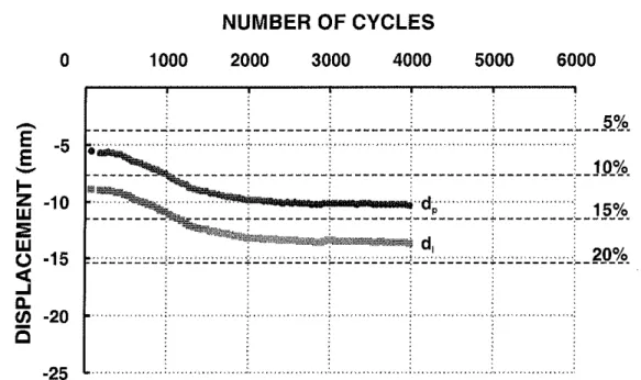
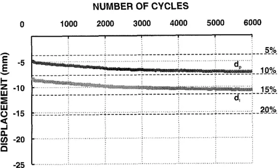
The MTS machine recorded the displacements of the crosshead at the peak of each loading and unloading cycle. At the end of each loading cycle, the load reached 45.4kg in compression and the crosshead displacement was at a maximum in compression. This displacement corresponded to the instantaneous indentation of the specimen, di. At the end of each unloading cycle, the load reached Okg and the crosshead displacement was at a minimum in compression. This displacement
IRC-IR800 Simulation of Reoeated Foot Traffic over Low-Slooe Roof Surfaces
represented the permanent indentation of the specimen, d,. It accounted for the relaxation of the specimen in half a cycle or 0.5s. Both indentations, di and d,, were recorded at intervals of 50s at the beginning of the tests to 300s at the end.
3.4 Measurement of Indentation
The roofing assemblies were allowed to relax for two days after the cyclic compression tests. A stiff steel strip was laid across the deepest spot of the indentation of the insulation specimen. A Mitutoyo digital micrometer was then aligned against the steel strip and the end of the micrometer was extended into the indentation for measurements. At least 5 measurements were made in the vicinity of the deepest spot of the indentation. After subtracting the thickness of the steel strip, an average and a standard deviation of the depth of indentation were determined. The indentations of the membranes and the fibreboard were also measured.
4. RESULTS
4.1 Static Test
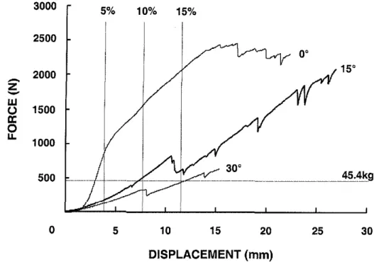
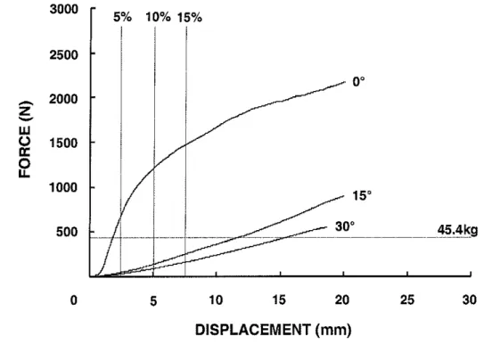
The force-displacement curves of the insulation samples under compression by the heel positioned at different angles are shown in Figures 4.1-4.3. The displacements corresponding to 5%, 10% and 15% of the sample thickness were marked on the Figures for reference. For the polyisocyanurate specimens, the force increased almost linearly with displacement until a sudden drop in load occurred, which corresponded to the fracture of the facer (Figure 4.1). The facer fractured at less than 45.4kg when the heel was positioned at 30". However, the facer fractured at a higher load when the heel was positioned at 0" or 15". When the heel was positioned at 15" or 30°, the indentations of the insulation specimens were greater than 10% of their thickness (i.e., 7.6mm) at 45.4kg. The phenolic specimens were brittle as indicated by the numerous small load drops on the force-displacement curves (Figure 4.2). The instantaneous indentation was less than 10% of the sample thickness at 45.4kg when the specimen was compressed with the heel positioned at 0' and 15". For the expanded polystyrene specimens, the force increased linearly for about 40% of its thickness when they were compressed with the heel positioned at 15' and 30" (Figure 4.3). These specimens were indented for more than 20% of their thickness when the load reached 45.4kg.
4.2 Dynamic Test
The results of the cyclic compression tests are summarized in Figures 4.4 - 4.16 and Table 4.1. The displacements corresponding to 5%, lo%, 15% and 20% of the sample thickness were marked on the Figures for reference. The curves generally consisted of two parts representing two different rates of indentation. At the beginning of the test (e.g., less than 1000 cycles), the rate of indentation was higher. It slowed down and approached a limiting value towards the end of the test (e.g., more than 2000 cycles).
DISPLACEMENT (mm)
Figure 4.1 Force-displacement curves for static compression test of polyisocyanurate insulation with loading head positioned at different angles
IRC-IF1800 Simulation of Repeated Foot Traific over Low-Slope Roof Surfaces
3000
-
0 5 10 15 20 25 30
DISPLACEMENT (mm)
2500
Figure 4.2 Force-displacement curves for static compression test of phenolic insulation with loading head positioned at different angles
5% 10% 15%
!
-
foot-IR800.doc NRC-IRC Build~ng Envelope and Structure Program (Roofing) Page 5
- . . . .. - .. - . -. . . -.
IRC-IR800 Simtllation of Repeated Foot Traffic over Lou-Slope Roof Suffaces . - . .. - . . . . . .. .- - . - . . -
0 5 10 15 20 25 30
DISPLACEMENT
(mm)
Figure 4.3 Force-displacement curves for static compression test of expanded polystyrene insulation with loading head positioned at different angles When the unprotected polyisocyanurate specimen was subjected to the cyclic compression test with the heel positioned at 15", the specimen was indented beyond 5% of its thickness in the first cycle (Figure 4.4a). This was consistent with the static test. The facer was punctured at around 500 cycles. The specimen was indented to 10% of its thickness at around 1000 cycles. The rate of indentation dropped significantly between 1500 to 2500 cycles and approached an indentation of 13% after 4000 cycles. When the angle between the heel and the specimen was increased to 30°, the sample was rapidly indented beyond 15% in the first 100 cycles (Figure 4.4b) and approached 20% after about 2000 cycles. When a PVC membrane was secured on the polyisocyanurate specimen with masking tape and the assembly was subjected to cyclic compression with the heel positioned at 15", the assembly was indented beyond 5% of its thickness in the first cycle. However, the rate of indentation was slow such that the indentation approached 7% after 4000 cycles (Figure 4.5a). This indentation was about half of that of the unprotected specimen (Figure 4.4a). When the angle between the heel and the specimen was increased to 30°, the specimen was indented over 10% in the first 500 cycles and approached 15% after 6000 cycles (Figure 4.5b). For comparison, the same final indentation was reached in the first 100 cycles for the polyisocyanurate specimen without the PVC membrane (Figure 4.4b).
Cap and base sheets of SBS modified bituminous membrane were torched onto the polyisocyanurate specimen and the assembly was subjected to cyclic compression. With the heel positioned at 15" the indentation of the assembly levelled to about 4% of the thickness of the insulation after about 500 cycles (Figure 4.6a). This indentation
IRC-R800 S;mulation of - Repeated Foot Traffic over Low-Slope Roof Surfaces
NUMBER OF CYCLES
1000 2000 3000 4000 5000 6000
NUMBER OF CYCLES
Figure 4.4 Instantaneous and permanent indentations of unprotected polyisocyanurate insulation specimens subjected to cyclic compression testing at (a) 15" and (b) 30".
IRC-.R~~OO S~mulation of Repeated Foot TraHic over Low-Slope Roof Surfaces ...
(a)
NUMBER OF CYCLES
NUMBER OF CYCLES
Figure 4.5 Instantaneous and permanent indentations of polyisocyanurate insulation specimens covered with a PVC membrane subjected to cyclic compression testing at (a) 15" and (b)
30".
IRC-IR800 Simulation of Repeated Foot Traffic over Low-Slope Roof Surfaces
NUMBER OF CYCLES
NUMBER OF CYCLES
1000 2000 3000 4000 5000 6000
Figure 4.6 Instantaneous and permanent indentations of polyisocyanurate insulation soecimens covered with modified bituminous membrane subiected to cyclic compression testing at (a) 15" and (b)
30".
...
IRC-IR800
-. Sirnulalion . . . of Repeated - . Foot Traffic over Lotv-Slope Roof Surfaces
NUMBER OF CYCLES
1000 2000 3000 4000 5000 6000
NUMBER OF CYCLES
1000 2000 3000 4000 5000 6000
Figure 4.7 Instantaneous and permanent indentations of polyisocyanurate insulation specimens covered with a PVC membrane and a fibreboard overlay subjected to cyclic compression testing at (a) 15" and (b) 30".
. - RC-.RE00 S~rnulation of Repeated Foot Traffic over Low-Slope Roof Surfaces
. . .
(a)
NUMBER OF CYCLES
NUMBER OF CYCLES
1000 2000 3000 4000 5000 6000
Figure 4.8 Instantaneous and permanent indentations of unprotected phenolic insulation specimens subjected to cyclic compression testing at (a) 15" and (b) 30".
IRC-IR800 Simulation of Repeated Foot Traffic over Low-Slope Roof Surfaces (a) NUMBER OF CYCLES 0 1000 2000 3000 4000 5000 6000 h
E
-5E
V I- -102
W 0 -15<
A P U) -20E
-25 NUMBER OF CYCLESFigure 4.9 Instantaneous and permanent indentations of phenolic insulation specimens covered with a PVC membrane subjected to cyclic compression testing at (a) 15" and (b) 30".
. . . -. -. . . . . . . .- -. ...- - IRC:R~OO Sirnulalion of Repeated Foor ... Traffic -. over Lofl-Slope Roof Surfaces
NUMBER
OF
CYCLESNUMBER
OF
CYCLES0 1000 2000 3000 4000 5000 6000
Figure 4.10 Instantaneous and permanent indentations of phenolic insulation specimens covered with modified bituminous membrane subjected to cyclic compression testing at (a) 15" and (b) 30".
IRC-IR800 Simulation of Repeated Foot Traffic over Low-Slope Roof Surfaces
(a)
NUMBER OF CYCLES
0 1000 2000 3000 4000 5000 6000
NUMBER OF CYCLES
Figure 4.11 Instantaneous and permanent indentations of phenolic insulation specimens covered with a PVC membrane and a fibreboard overlay subjected to cyclic compression testing at (a) 15" and (b) 30".
... - ... -- . . . - . -. . .
IRC- RE00 . . . Simulation of Repeated Foot Traffic over Lovd-Slope Roof Surfaces . . .
N U M B E R
OF
CYCLES
0 1000 2000 3000 4000 5000 6000
Figure 4.12 Instantaneous and permanent indentations of phenolic insulation specimen covered with fibreboard subjected to cyclic compression testing at 30".
. . . . . .
IRC- R800 Simulation of Repeated Foor Traffic over Low-Slope Roof ~ u i a ; e s
-. - - . . - . . - . . NUMBER OF CYCLES 0 1000 2000 3000 4000 5000 6000 h
E
-5E
Y+
Z: -10w
0 -15a
An.
V) -20E
-25 NUMBER OF CYCLES 1000 2000 3000 4000 5000 6000Figure 4.13 Instantaneous and permanent indentations of unprotected polystyrene insulation specimens subjected to cyclic compression testing at (a) 15" and (b) 30".
IRC-IR800 Simulation of Repeated Foot Traffic over Low-Slope Roof Surfaces
NUMBER OF CYCLES
NUMBER OF CYCLES
0 1000 2000 3000 4000 5000 6000
Figure 4.14 Instantaneous and permanent indentations of polystyrene insulation specimens covered with a PVC membrane subjected to cyclic compression testing at (a) 15" and (b) 30".
-. . . .
IRC-IR800 Simulatfon of Repeated F& Traffic over Lovi-Slope Roof surfaces - - . . . . . . .. . . ..
NUMBER OF CYCLES
1000 2000 3000 4000 5000 6000
NUMBER OF CYCLES
1000 2000 3000 4000 5000 6000
Figure 4.15 Instantaneous and permanent indentations of polystyrene insulation specimens covered with modified bituminous membrane subjected to cyclic compression testing at (a) 15" and (b) 30".
... ....
... - .. - -
idc-IRBOO
-. Sirnulat,on of Repeated Fool Traffrc ... . . . over Low-Slope Roof Surfaces -. ...
NUMBER OF CYCLES
1000 2000 3000 4000 5000 6000
NUMBER OF CYCLES
1000 2000 3000 4000 5000 6000
Figure 4.16 Instantaneous and permanent indentations of polystyrene insulation soecimens covered with a PVC membrane and a fibreboard overlav subjected to cyclic compression testing at (a) 15" and (b)
30".
1
o
Table 4.1 Summary of cyclic compression testing results.-0 m (D (D N 0
* PI = polyisocyanurate, PH = phenolic, PS = polystyrene
"UNPROTECTED = insulation alone, PVC =with a reinforced PVC membrane taped on, MB =with a modified bitumen membrane torched on, PVC-FB = with a reinforced PVC membrane and wood fibreboard taped on, FB = with wood fibreboard taped on
IRC-IR800 Simulation of Repeated Foot Traffic over Low-Slope Roof Surfaces
was about one third that of the unprotected polyisocyanurate insulation (Figure 4.4a). When the loading angle was increased to 30°, the indentation of the assembly approached 7% after 2000 cycles (Figure 4.6b). This value was again about one third that of the unprotected specimen. When a fibreboard overlay and a PVC membrane were secured on a polyisocyanurate specimen and the assembly was subjected to cyclic compression with the heel positioned at 15", the indentation of the assembly was quickly levelled to about 3 mm after about 1000 cycles (Figure 4.7a). This corresponded to less than 5% of the thickness of the insulation specimen. Similar behaviour was observed when the loading angle was increased to 30". However, the difference between di and d, was slightly higher at 30' than at 15" (Figures 4.7). Compared to the unprotected insulation samples (Figure 4.4), the PVC-fibreboard arrangement had greatly reduced the indentation of the polyisocyanurate.
When the unprotected phenolic specimen was subjected to cyclic compression testing with the heel positioned at 15", the specimen was indented beyond 5% of its thickness in the first cycle (Figure 4.8a). The specimen was indented to 10% of its thickness at around 150 cycles. The rate of indentation dropped significantly between 1500 to 2500 cycles and levelled to an indentation of 13%. When the loading angle was increased to 30°, the specimen was rapidly indented over 15% in the first 100 cycles and approached 18% after 2000 cycles (Figure 4.8b). When a PVC membrane was secured on the phenolic specimen with masking tape and the assembly subjected to cyclic compression with the heel positioned at 15", the assembly was indented beyond 5% in the first cycle. However, the rate of indentation was slow such that the indentation approached 10% after 6000 cycles (Figure 4.9a). When the angle between the heel and the specimen was increased to 30", the sample was indented over 10% in the first 200 cycles and approached 13% after 6000 cycles (Figure 4.9b). With the PVC membrane, the indentation of the phenolic sample was reduced by 3-4% of its thickness.
Cap and base sheets of SBS modified bituminous membrane were torched on the phenolic specimen and the assembly was subjected to cyclic compression with the heel positioned at 15". This assembly was only indented slightly over 5% after 1000 cycles (Figure 4.10a). This value corresponded to slightly less than half of that of the unprotected insulation. Similar behaviour was observed when the loading angle was increased to 30°, the indentation of the assembly levelled to about 6% after 3000 cycles (Figure 4.10b), which was about one third of the corresponding value of the unprotected insulation. When a fibreboard overlay and a PVC membrane were secured onto a phenolic insulation specimen, and the assembly subjected to cyclic compression with the heel positioned at 15", the indentation of the assembly was quickly levelled to about 3 mm after about 1000 cycles (Figure 4.1 la). Similar behaviour was observed when the loading angle was increased to 30°, however, the difference between the dl and d, was slightly higher at 30" than at 15" (Figure 4.1 1). Compared to the unprotected insulation sample (Figure 4.8), the PVC membrane and the fibreboard overlay greatly reduced the indentation of the insulation samples.
To examine the effect of fibreboard overlay alone, an assembly was made by attaching fibreboard on a phenolic specimen. The assembly was subjected to cyclic compression with the heel positioned at 30". The cyclic compression behaviour was
IRC-IR800 Simulation of Repeated Foot Traffic over Low-Slope Roof Surfaces
similar to the PVC-fibreboard combination, with the indentation slightly higher by about 1 % in thickness (Figures 4.12).
When the unprotected expanded polystyrene sample was subjected to cyclic compression testing with the heel positioned at 15", the sample was indented beyond 10% of its thickness in the first cycle (Figure 4.13a). The sample was indented to 15% of its thickness at around 500 cycles. The rate of indentation dropped significantly between 1000 to 2000 cycles and reached an indentation of 20% at around 3000 cycles. When the loading angle was increased to 30°, the sample was indented over 20% in the first 100 cycles (Figure 4.13b). When a PVC membrane was secured on the polystyrene specimen with masking tape and the assembly was subjected to cyclic compression with the heel positioned at 15", the assembly was indented beyond 10% in the first cycle and it reached 15% after 1000 cycles (Figure 4.14a). The PVC membrane reduced the indentation by 5% of the thickness of the polystyrene sample. When the loading angle was increased to 30°, the sample was indented 15% after 200 cycles and reached beyond 20% after approximately 1500 cycles (Figure 4.14b). Compared to the unprotected polystyrene sample which was indented 20% in the first cycle (Figure 4.6b), the PVC membrane reduced the indentation of the insulation sample significantly.
When the modified bituminous membrane covered polystyrene sample was subjected to cyclic compression with the heel positioned at 15", the indentation approached 10% after 3000 cycles (Figure 4.15a). Similar behaviour was observed when the angle was increased to 30" (Figure 4.15b). Compared to the unprotected polystyrene sample which was indented to 20% in the first cycle at 30" loading angle (Figure 4.13b), the modified bituminous membrane greatly reduced the indentation of the insulation sample. When a fibreboard overlay and a PVC membrane were secured onto the polystyrene sample and the assembly was subjected to cyclic compression with the heel positioned at 15", the indentation of the assembly was quickly levelled to about 3 - 4 mm after about 1000 cycles (Figure 4.16a). Similar behaviour was observed when the loading angle was increased to 30°, however, the difference between the di and d, was slightly higher at 30" than at 15" (Figures 4.16b). Compared to the unprotected insulation samples (Figures 4.13), the PVC membrane and the fibreboard overlay reduced the indentation of the insulation samples greatly.
4.3 Measurement of Indentation
The rate of indentation started to plateau at about 2000 cycles (Figures 4.4 - 4.16 ). The permanent indentation at the 2000th cycle for all the samples, as recorded by the test machine during cyclic testing, is shown in Figure 4.17 and summarized in Table 4.2. For all the unprotected insulation samples, the indentation at the 2000'~ cycle was about 9-10mm when subjected to cyclic loading at an angle of 15" and about 13-16mm at 30". When the insulation sample was covered with a PVC membrane, the indentation at the 2000th cycle was reduced to about 5-8mm at 15" and 9-1 l m m at 30' for all three samples. With modified bituminous membranes covering the insulation samples, the reduction in indentation was even greater. The assembly was indented to about 2-6 mm at the 2000th cycle, at both loading angles. The PVC membrane-
-. . . . . . .. . .
IRC-.R800
- -. .. .- - - Simulation of Repealed Foot Traffic over Low-Slope ~ o o f ~ u r f a c i s -.
(a)
TEST CONDITIONS
UNPROTECTED PVC ME PVC-FB FB
TEST CONDITIONS
Figure 4.17 Instantaneous indentation at the 2000'~ cycle for different test assemblies subjected to a loading angle of (a) 15" and (b) 30".
Table 4.2 Summary of indentations on test assemblies,
* PI = polyisocyanurate, PH = phenolic, PS = polystyrene
**UNPROTECTED = insulation alone, PVC = with a reinforced PVC membrane taped on, MB =with a modified bitumen membrane torched on, PVC-FB = with a reinforced PVC membrane and wood fibreboard taped on, FB =with wood fibreboard taped on
IRC-IR800 Simulation of Repeated Foot Traffic over Low-Slope Roof Surfaces
fibreboard overlay-insulation combination produced similar reduction in indentation as the modified bituminous membrane. The assembly was indented about 2-5mm after 2000 cycles, at both loading angles.
The roofing assemblies were allowed to recover for two days in the laboratory after the cyclic compression tests, after which they were visually inspected. The facer of the unprotected polyisocyanurate specimen that had been subjected to a loading angle of 15" was torn and broken along the outer edge of the heel mark (Figure 4.18a). With the loading angle at 30", the facer had cleanly broken along the edge of the heel and a deep indentation was observed (Figure 4.18b). The facer of the polyisocyanurate specimen that had been beneath the PVC membrane was torn and broken (Figure 4.18~). However the damage was clearly not as severe as on the unprotected specimens. The facer of the polyisocyanurate specimen that had been beneath the modified bituminous membrane was only slightly torn open after being subjected to cyclic compression at a loading angle of 30" (Figure 4.18d). The area directly under the heel was puffy and spongy to touch. The facer of the unprotected phenolic specimen was cleanly broken along the edge of the heel (Figure 4.19a). The facer of the phenolic specimen that had been underneath the PVC membrane was torn open but the specimen was not compressed as severely as the unprotected one (Figure 4.19b). Only a slight indentation was observed on the phenolic insulation that had been beneath the modified bituminous membrane (Figure 4.19~). The facer remained intact but the area under the heel was puffy and spongy to touch. When the facer was cut open along the edge of the heel mark and lifted, the insulation underneath was found to be crushed into small pieces. These small pieces were removed from the specimen and the area after removal of the broken pieces is shown in Figure 4.19d. An imprint of the heel was observed in the unprotected polystyrene specimen subjected to cyclic compression (Figure 4.20a). A crack was observed at the area where the back of the heel contacted the specimen at 15" (Figure 4.20a). Several cracks were observed in the same area when the loading angle was increased to 30" (Figure 4.20b). The indented area on the polystyrene underneath the PVC membrane was smooth, without any imprints of the heel (Figure 4 . 2 0 ~ ) . Two small cracks were observed on the surface of the insulation: one near the back of the heel and another near the front of the heel. A slight indentation was observed on the polystyrene underneath the modified bituminous membrane (Figure 4.20d). The recessed area was puffy to touch.
The appearance of the indentation on the surface of the modified bituminous membrane was the same for all samples. After two days of recovery, the indentation was almost invisible. It was very shallow and appeared as a curved mark on the cap sheet (Figure 4.21a). The cyclic compression produced slight indentation and small cracks on the surface of the fibreboard underneath the PVC membrane (Figure 4.21 b). However, the insulation underneath the fibreboard was not indented.
The indentations on the membrane, the fibreboard and the insulation sample were measured and are summarized in Figures 4.22 and Table 4.2. Note that the number of cycles each specimen went through was not the same (ranged from 2000 to 12000 cycles), therefore, the values cannot be compared directly. However, since the rate indentation started to plateau and the indentation did not increase much after 2000
IRC-IR800 Simulation of Repeated Foot Traffic over Low-Slope Roof Surfaces
- - . .-
IRC-IR800 Simulation of Repeated Foot Traffic over Low-Slope Roof Surfaces
. . . - . -. -. -- -. .- . . . .
I R C - 1 ~ 8 0 0 . Sirncrlalion of Repeated Foor Traffic over Lor/-Slope Roof Surfaces
(a) HINSULATION UMEMBRANE BFIBREBOARD UNPROTECTED PVC MB PVC-FB TEST CONDITIONS BlNSULATlON OMEMBRANE FIBREBOARD UNPROTECTED PVC MB PVC-FB FB TEST CONDITIONS
Figure 4.22 Indentation after two days of recovery for different test assemblies subjected to a loading angle of (a) 15" and (b) 30".
. . . -. . . . . .. . . . . - - - - .. -- IRC- R800 Simulation of Repeated Foot Traffic over Low-Slope Roof Surfaces . . . . . .. . .
cycles (the difference being less than 2% in thickness in general), direct comparison of the final indentations should not introduce significant error.
The final indentations of the unprotected insulation samples after two days was similar for the polyisocyanurate and for the phenolic at each loading angle (Figures 4.22). The unprotected polystyrene had a significantly higher final indentation than the other two insulation samples. When a PVC membrane was secured onto the insulation, the final indentation of the insulation samples decreased (5 - 40%): more for polystyrene and less for polyisocyanurate and phenolic. The indentation of the PVC membrane itself was negligible. The modified bituminous membrane recovered a lot after two days and the final indentation on the surface was less than 3mm. The modified bituminous membranes were peeled off from the insulation samples carefully. Slight indentation on the insulation samples was observed. The area under the heel was puffy for all the insulation samples. No indentation was observed on the insulation samples underneath the fibreboard or the PVC-fibreboard combination. The final indentation of the fibreboards was less than 3mm. The final indentation of the PVC membrane covering the fibreboard was negligible.
The indentation on the insulation samples generally decreased after the test due to the partial recovery of the cellular foam. The recovery from indentation is defined by the permanent indentation registered by the testing machine in the final cycle minus the final indentation of the roofing assembly measured after two days of recovery divided by the permanent indentation registered. The percentage recovery from indentation for all specimens is summarized in Figure 4.23 and Table 4.2. For the unprotected insulation samples, the recovery of indentation was better at the smaller loading angle. Also, the polyisocyanurate recovered significantly more than phenolic and polystyrene. For the polystyrene, the final indentation measured on the sample was higher than the permanent indentation registered by the testing machine. This strange observation is discussed in Section 5. The insulation specimens underneath the PVC membrane recovered about 25% at 15" and about 5% at 30" for all three samples.
Only slight indentations were observed on the insulation samples that had been covered with the modified bituminous membrane. No indentation was visually observed on the insulation samples that had been covered with either the PVC membrane- fibreboard arrangement or with fibreboard alone. As a result, the recovery was mostly in the membrane and/or the fibreboard. The recovery of the modified bituminous membrane was high, ranging from 50% to 90%, depending on the loading angle. The fibreboard under the PVC membrane recovered between 40% to 70% for all specimens. The fibreboard without the PVC membrane recovered about 45% after being subjected to a loading angle of 30" over phenolic insulation.
5. DISCUSSION
The results of the cyclic compression tests (Figures 4.4 - 4.16) showed that the displacement versus number of cycles (n) curves generally consisted of two parts representing two different rates of indentation. The higher indentation rate at the beginning of the test corresponded to the crushing and compacting of the insulation material. The cyclic compression process essentially removed the cell volume of the
IRC-IR800 S,rnulat,on of Repeated Fool ~Gffrc over Low-Slope Roof Surfaces . - . - - - .- - - --- - . . -. - [UNPROTECTED PVC MB PVC-FB -20 TEST CONDITIONS
[
PI PH PS PI PH PS PI PH PS PI PH PS PH -20 UNPROTECTED PVC ME PVC-FB FB TEST CONDITIONSFigure 4.23 Percent recovery from indentation for different test assemblies subjected to an loading angle of (a) 15" and (b) 30".
IRC-IF1800 Simulation of Repeated Foot Traffic over Low-Slope Roof Surfaces
insulation material by compacting it. The compaction occurred quickly at the early stage. After the cell volume had been reduced to a certain extent, the compacted material started to "spring back". At this stage, the insulation became difficult to compress since it was not reducing the cell volume but compacting the plastic material that made up the insulation. As a result, the rate of indentation decreased and approached a limiting value. In addition, the contact area increased as the heel dug deeper into the specimen. This increased contact area reduced the stress acting on the specimen, thus reducing the rate of indentation.
The permanent indentation and the rate of indentation for the unprotected insulation increased with increasing angle between the heel and the insulation as expected. As the angle increased, the contact area decreased and the stress increased. This led to increase in both the permanent indentation and the rate of indentation. It was also observed that this high rate of indentation occurred at the beginning of the test only (i.e., number of cycle < 500). The higher stress created by increasing the angle between the heel and the insulation reduced the cell volume quicker.
The PVC membrane helps to reduce insulation damage by dispersing repeated compressive loads over a larger area. The membrane was secured on the four edges on all four sides of the specimen with masking tape. This provided slight tension on the membrane but allowed freedom for flexural movement, which is analogous to PVC membranes that are mechanically fastened in the field. This flexural movement of the membrane helped distribute the load, thus reducing the compressive damage to the insulation underneath. This load distribution was visually evident from the smooth recessed area on the PVC-covered polystyrene specimen (Figure 4.20d) compared to the sharp heel imprint on the unprotected specimen (Figure 4.20b). Quantitatively, this load distribution was evident from the significant reduction in instantaneous indentation (Figure 4.17), final indentation (Figure 4.22) and the rate of indentation (Figure 4.5, 4.9 and 4.14). Since the PVC membrane recovered much more than the insulation underneath (Figure 4.22), a void existed between the PVC membrane and the insulation. This void is not visible on the roof.
The two-ply modified bituminous membrane provided better insulation protection from reoeated com~ressive loads than the PVC membrane. The modified bituminous membranes were thick and pliable, thus absorbing a part of the applied energy. The instantaneous indentation of the insulation was reduced by 10% to 40% (Figure 4.17) and the final indentation by more than 80% (Figure 4.22). The rate of indentation was reduced significantly as well (Figure 4.6, 4.10 and 4.15). Note that when the torched-on membranes were peeled off the insulations carefully, the recessed areas were puffy. The facer of the polyisocyanurate was torn open slightly, indicating that damage was incurred on the insulation despite the protection by the membrane. Although the facer of the phenolic insulation remained intact after the test, the area under the heel was puffy. When the facer was cut open and peeled off, the numerous small broken pieces of foam material were found underneath. The cellular foam in this area was definitely damaged by the repeated compressive action of the heel. The recessed area on the polystyrene was puffy too. Although the foam was still intact, it is likely that the cell structure was damaged. Since the modified bituminous membrane recovered a great
,RC-IR800 Simulation of Repeated Foot Traffic over Lot./-Slope ~ G i ~ u r f a c e s
- --- -. ...
deal due to its viscoelastic nature, the indentation on the membrane was almost invisible after a few days. As a result, any damage to the insulation by foot traffic may not be readily observable on a modified bitumen roof.
The PVC-fibreboard combination provided the best protection against cyclic compression for the insulations. The final indentation of the fibreboard was only about 3mm and no indentation was observed on the insulation. It is evident that the stiff fibreboard was very effective in dispersing the concentrated compressive load under the heel to a larger area, thus reducing the stress acting on the surface of the insulation. Comparing the phenolic insulation covered with the PVC-fibreboard arrangement with that covered with fibreboard alone, only slight differences were noted. No indentation was observed in the phenolic insulation underneath. This confirms that the use of fibreboard during construction work on the roof provides protection to the insulation against damage caused by foot traffic.
The permanent indentation (the displacement of the crosshead at the peak of each unloading cycle) is a better representation of the permanent deformation of the insulation sample than the instantaneous indentation (the displacement of the crosshead at the peak of the loading cycle). This is because the former accounted for some recovery of the deformation induced by the compressive force. However, the duration of this recovery was only half a cycle, or 0.5s. The insulation material should recover further if more time is available. As a result, the permanent deformation is not truly permanent. The final indentation after two days of recovery is a better representation of the permanent deformation of the insulation samples than the permanent indentation as registered by the testing machine because more time is allowed for recovery.
The indentation on the insulation sample generally decreased after the test due to recovery of the cell content. However, for polystyrene, the final indentation measured on the sample was higher than the permanent indentation registered by the testing machine. This is because the response of the testing machine was not fast enough for this material. During unloading, the actuator moved down to pull the specimen away from the heel. Because the polystyrene was slow in recovery and the machine was seeking for ON in 0.5s, the actuator overshot - meaning that the heel was not in contact with the sample. As a result, the indentation registered with the machine was lower than the actual indentation on the polystyrene specimen.
The recovery from indentation was significantly higher for insulation samples underneath modified bituminous membranes and fibreboards than for the unprotected and the PVC-covered samples. For the unprotected and the PVC-covered samples, a large part of the compressive load was exerted on the insulation. Some of the cells were damaged, thus the recovery of the insulation was not very high. This was especially true for the phenolic which is more brittle. On the other hand, the modified bituminous membranes were more effective in distributing the load because they were thicker. In addition, their viscoelastic nature also increased their recovery from indentation. The fibreboard bore and distributed the applied load more uniformly over the insulation samples. The insulation was slightly compressed but no local damage was produced.
..
. . . . . . . .. .
IRC-IRE00 ~im"lation of Repeated Foot Traffic over Lo#-Slope Roof Surfaces --A
This test is simple to perform but it does not properly simulate the walking mechanics. When a person walks, the load shifts from the back to the front of the shoe -the contact area between the shoe and the roofing assembly increases. This reduces the stress acting on the roofing assembly. Therefore, this experimental approach may produce more severe damage. On the other hand, the load at the beginning of a step should be close to the average weight of a roofer, which is much higher than 45.4kg as applied in this study. Therefore, the results obtained may underestimate the damage incurred. It is thought that the use of a smaller load but a more severe loading configuration may balance out the opposite effects.
6. CONCLUSIONS
1. When tested with the heel positioned at 15" to the specimen, the unprotected insulation samples reached an indentation of 10% of its thickness at around 1000 cycles for the polyisocyanurate, after 150 cycles for the phenolic and in the first cycle for the expanded polystyrene. When the loading angle was increased to 30°, both the polyisocyanurate and the phenolic insulations were indented beyond 15% in 100 cycles while the expanded polystyrene insulation was compressed to an indentation of over 20% in the first cycle.
2 . The PVC membrane provided protection for the insulation samples against repeated compression
-
both the permanent deformation and the rate of indentation on the insulation samples decreased. Both polyisocyanurate and phenolic insulations amroached 8-9% indentation after 6000 cvcles while exuanded uolvstvrene iis'ulation reached 15% after 1000 cycles ata
loading angle of 15". ' when theloading angle was increased to 30", both the PVC-covered polyisocyanurate and phenolic insulations were indented beyond 10% in the first 500 cycles and approached 13-15% in 6000 cycles. However, the polystyrene insulation was indented beyond 15% in the first 200 cycles and reached 20% in less than 2000 cycles.
3. The modified bituminous membrane (2-ply cap plus base sheets) offered better protection for the insulation samples against repeated compression than the PVC membrane
-
both the permanent indentation and the rate of indentation on the insulation samples were reduced significantly. The modified bituminous membrane covered polyisocyanurate and phenolic insulations were indented 3-5% at 15" loading angle and 6-7% at 30". The indentation was higher for the modified bituminous membrane covered polystyrene insulation, which was indented 9-10%.4. The PVC-fibreboard arrangement provided the best protection for the insulation samples against repeated compression. The assemblies were indented 3-5 mm for all samples at the two loading angles. No indentation was visible on the any insulation beneath the fibreboard.
5. Insulation underneath fibreboard alone showed similar results to the PVC-fibreboard arrangement.
IRC-1R800 S,mulation of Repeated Foot Traffic over Low-Slope Roof ~ Z a c e s -- - - -. . - ..... . . . . . . . . . .- . . -
6. The PVC membrane reduced the final indentation (after two days of recovery) of the insulations by 15-40%. Both the modified bituminous membrane and the PVC membrane-fibreboard arrangement reduced the final indentations by 70-80%.
7. Although the insulation samples protected by the modified bituminous membrane and the fibreboard under the PVC membrane showed similar indentations, the insulations underneath the modified bituminous membrane showed localized crushing but those under the PVC-fibreboard arrangement did not. This indicated that the fibreboard provided better protection for the insulation against foot traffic. 8. The recoveries from indentation of the PVC membrane and the modified bituminous
membrane were very much higher than those of the insulations. As a result, shallow indentations on any membrane surfaces might mislead one to underestimate the insulation damage incurred by foot traffic in the roofing systems.


![[PDF] Cours Introduction à C#.Net pdf | formation informatique](data:image/gif;base64,R0lGODlhAQABAIAAAP///wAAACH5BAEAAAAALAAAAAABAAEAAAICRAEAOw==)