Publisher’s version / Version de l'éditeur:
Vous avez des questions? Nous pouvons vous aider. Pour communiquer directement avec un auteur, consultez la
première page de la revue dans laquelle son article a été publié afin de trouver ses coordonnées. Si vous n’arrivez pas à les repérer, communiquez avec nous à [email protected].
Questions? Contact the NRC Publications Archive team at
[email protected]. If you wish to email the authors directly, please see the first page of the publication for their contact information.
https://publications-cnrc.canada.ca/fra/droits
L’accès à ce site Web et l’utilisation de son contenu sont assujettis aux conditions présentées dans le site
LISEZ CES CONDITIONS ATTENTIVEMENT AVANT D’UTILISER CE SITE WEB.
107th Annual Meeting & Exposition of the American Ceramic Society [Proceedings], pp. 1-10, 2005-04-10
READ THESE TERMS AND CONDITIONS CAREFULLY BEFORE USING THIS WEBSITE.
https://nrc-publications.canada.ca/eng/copyright
NRC Publications Archive Record / Notice des Archives des publications du CNRC :
https://nrc-publications.canada.ca/eng/view/object/?id=984fb687-c7e6-419c-81a2-03a4ed46b6c6 https://publications-cnrc.canada.ca/fra/voir/objet/?id=984fb687-c7e6-419c-81a2-03a4ed46b6c6
NRC Publications Archive
Archives des publications du CNRC
This publication could be one of several versions: author’s original, accepted manuscript or the publisher’s version. / La version de cette publication peut être l’une des suivantes : la version prépublication de l’auteur, la version acceptée du manuscrit ou la version de l’éditeur.
Access and use of this website and the material on it are subject to the Terms and Conditions set forth at Characterization and properties of calcium silicate hydrate polymer nanocomposites
Characterization and properties of calcium silicate hydrate polymer nanocomposites
Mojumdar, S.C.; Raki, L.
NRCC-48333
A version of this document is published in / Une version de ce document se trouve dans : 107th Annual Meeting Proceeding, Baltimore, D.C., April 10-13, 2005, pp. 1-10
Characterization and Properties of Calcium Silicate Hydrates Nanocomposites
Journal: 107th Annual Meeting & Exposition of The American Ceramic Society
Manuscript ID: AM05-053.R2
Symposium Abbreviation: CEM
Date Submitted by the Author: n/a
Complete List of Authors: Raki, Laila;
Keywords: microscopy, cements, nanocomposites
CHARACTERIZATION AND PROPERTIES OF CALCIUM SILICATE HYDRATE POLYMER NANOCOMPOSITES
S. C. Mojumdar and L. Raki
Institute for Research in Construction, National Research Council Canada, M-20, 1200 Montreal Road, Ottawa, Ontario K1A 0R6, Canada, e-mail: [email protected]
ABSTRACT
High molecular weight nonionic polymer-poly(vinyl alcohol) (PVA) in different concentrations has been incorporated into the calcium silicate hydrate (C-S-H) structure during precipitation of quasicrystalline C-S-H from aqueous solution. Ca/Si = 0.7 and various PVA concentrations (0.05-0.75 g/g Ca salt) were used for a series of C-S-H-polymer nanocomposite (C-S-HPN) materials synthesis. Synthetic C-S-H and C-S-HPN materials were characterized by Fourier-transform infrared (FTIR) spectroscopy, scanning electron microscopy (SEM) and atomic force microscopy (AFM). The compositions and structures of the C-S-H and C-S-HPN materials were studied by SEM and FTIR spectra. FTIR spectra confirms the presence of PVA in C-S-HPN materials. The SEM and AFM micrographs of C-S-H and C-S-HPN materials with different PVA contents exhibit the significant differences in their morphologies.
INTRODUCTION
Nanomaterials consisting of inorganic nanolayers of C-S-H and organic polymers have evoked intense research interests lately because their unique characteristics create many potentially commercial applications [1-2]. Nanocomposite materials are reported to promote the thermal, mechanical, molecular barrier, flame retardant and corrosion protection properties of polymers at low clay loading [3].
We define nanocomposites as particle-filled polymers for which at least one dimension of the dispersed particles is in the nanometer range. One can distinguish three types of nanocomposites, depending on how many dimensions of the dispersed particles are in the nanometer range [4]. When the three dimensions are in the order of nanometers, we are dealing with isodimensional nanoparticles, such as spherical silica nanoparticles obtained by in situ sol-gel methods [5, 6] or by polymerization promoted directly from their surface [7], but also can include semiconductor nanoclusters [8] and others [9]. When two dimensions are in nanometer scale and the third is larger, forming an elongated structure, we speak about nanotubes or whiskers as, for example, carbon nanotube [10] or cellulose whiskers [11, 12], which are extensively studied as reinforcing nanofillers yielding materials with exceptional properties. The third type of nanocomposites is characterized by only one dimension in the nanometer range. In this case the filler is present in the form of sheets of one to a few nanometer thick to hundreds to thousands nanometers long. This family of composites can be gathered under the name of polymer-layered crystal nanocomposites, and their study is the main objective of this contribution.
Three main types of composites may be obtained when a polymer is associated with a layered structure. When the polymer is unable to intercalate between the layered sheets, a phase-separated composite is obtained, whose properties stay in the same range as traditional microcomposites. Besides this classical family of composites, two types of nanocomposites can be distinguished. An “intercalated” structure in which a single (and sometimes more than one) extended polymer chain is intercalated between the inorganic layers resulting in a well-ordered
multilayer morphology built up with alternating inorganic and polymeric layers. When the layers are completely and uniformly dispersed in a continuous polymer matrix, an “exfoliated or delaminated” structure is obtained. Other intermediate organizations can exist presenting both intercalation and exfoliation. In this case, a broadening of the diffraction peak is often observed [4]. The aim of this study is the systematic investigation of C-S-HPN layered structure nanocomposites by AFM, SEM and FTIR spectral analysis. This investigation opens up new routes to develop cement-polymer-based nanocomposites for future potential application in the construction field, such as coatings for corrosion protection, for fire retardancy and to promote the thermal, mechanical and molecular barrier of polymers. The study will also help to open up many other developments in construction field, including nano-molecular structures to make asphalt and concrete more resistant to water; materials to block ultraviolet and infrared radiation; materials for cheaper and durable housing, surfaces, glues, concrete, and heat and light exclusion; and self-cleaning for windows, mirrors and toilets.
EXPERIMENTAL
Materials, synthesis and analytical procedures are described in [12-14]. H and C-S-HPN materials with PVA content of (0.0 and 0.05, 0.15, 0.5 and 0.75 g/g Ca salt) were synthesized by gradually adding calcium nitrate solution (1 mol/L) with continual stirring under nitrogen to sodium silicate solution, which was pre-dissolved with PVA (only for the synthesis of C-S-HPN materials) in CO2– free de-ionized water. The initial Ca/Si molar ratio was 0.7 for
C-S-H and all C-S-HPN materials. The pH value was kept between 13.1-13.4 by adding NaOH solution (4.0 M) during the precipitation of C-S-H. After aging the suspension at 60 0C for seven days with continuous stirring, the precipitate was separated by vacuum filtration and washed with CO2 – free de-ionized water to remove sodium and nitrate ions and any residual PVA. The
precipitates were then washed with acetone and dried at 60 °C in a vacuum oven for 7 days. RESULTS AND DISCUSSION
AFM are commonly used to map the surface structure and topography of different objects and devices. AFM measurement was performed on bulk PVA, C-S-H and C-S-HPN materials films. Observation of the all materials films was done using AC mode. This AFM mode was chosen to investigate the topography and morphology of PVA, C-S-H and C-S-HPN as well as to illustrate the fundamental use of this AFM mode. Topographical and phase images of PVA, C-S-H and C-S-C-S-HPN materials, achieved by AFM are presented in Figs 1-2. There are significant differences between the topographical and phase images of PVA, C-S-H and C-S-HPN materials. The differences in morphology of the various C-S-HPN materials seen in these observations can be explained by the fact that the type of C-S-HPN materials formed depends on the polymer concentration in solution.
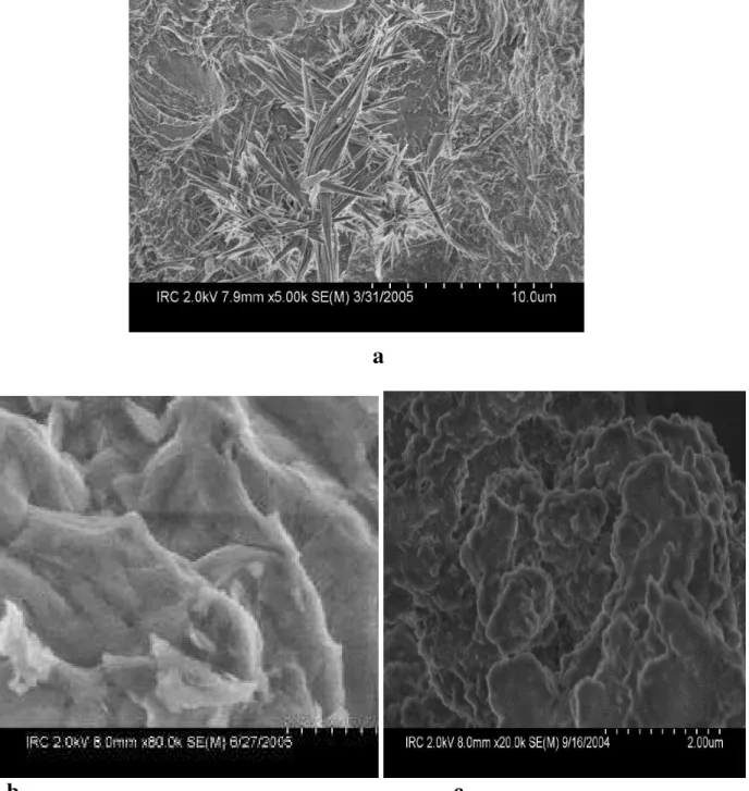
When PVA polymer was added to inorganic material, crystallites were initiated and grown in the immediate vicinity of the inorganic surface, which was extensively studied by Strawhecker and Manias using AFM [15]. In our study, we have observed the similar crystal growth in SEM image of C-S-HPN materials (Fig. 3a). It is believed that this is due to the strong specific interactions between the inorganic surfaces and PVA. The compositions of the materials were determined by EDS. The PVA (vinyl alcohol) group forms hydrogen bonds with the silicate oxygen, which dominate the cleavage plane of C-S-H. Moreover, due to the atomically smooth C-S-H surface, these specific interactions are expected to force chains to create long adsorbed trains, which in turn will promote a strongly interacting second layer of PVA to crystallize on top
Page 2 of 10 107th Annual Meeting, Exposition, and Technology Fair of The American Ceramic Society
of them. Thus, this C-S-H surface epitaxial/nucleating effect can be “felt” through many layers of polymer, causing a long-range collection and crystallization of PVA from the surface of the silicate. Therefore, these sites tend to act as nucleating sites for the PVA crystallites. Accordingly, scans of the C-S-HPN materials show many more crystallites per area compared to the neat PVA, as all the inorganic silicate fillers nucleate polymer crystallites. The PVA/C-S-H specific interactions decrease the surface energy necessary to create/nucleate polymer crystals, and thus, the crystalline regions tend to nucleate around the silicate surfaces. These new, silicate-induced PVA crystal phase is promoted by the existence of the C-S-H layers and forms at the expense of the bulk PVA crystalline phase. The observations, which have been discussed in this study, are comparable to the results, which were published by other researchers [15, 16].
Fig. 1 The AFM (topographical (left) and phase (right) micrographs of C-S-H (top) and
Fig. 2 The AFM (topographical (left) and phase (right) micrographs of C-S-HPN materials (PVA
= 0.5, top) and (PVA 100 %, bottom).
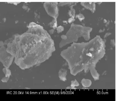
The SEM micrographs of pure PVA, synthetic C-S-H and C-S-HPN materials are shown in Figs. 3-6. Fig. 3 represents SEM images of crystal growth in surface of the materials (a), C-S-H (b) and PVA (c). For C-S-H, the particles display a sinuous surface, typical of this material [17]. PVA has a semi-amorphous character, as it has been confirmed by XRD results [12]. Significant differences in SEM micrographs of C-S-H, PVA and C-S-HPN materials with different polymer ratios are observed (Figs. 3-5). A clear example of two phases C-S-HPN materials is presented in
Page 4 of 10 107th Annual Meeting, Exposition, and Technology Fair of The American Ceramic Society
Fig. 5 b. The phase I (left) has a lower carbon (PVA) content than the phase II (right) that contains as much as 4x more carbon, as analyzed by EDS. It can be concluded on the basis of SEM, carbon content and XRD results that phase I is the intercalated and phase II is the exfoliated C-S-HPN materials.
a
b c
Fig. 3 The SEM micrographs: an example of initiation and growth of crystallites in the
immediate vicinity of the inorganic surface (a), model C-S-H (b) and PVA (c), magnification is 2000x.
a
b
Fig. 4 The SEM micrographs of two model C-S-HPN materials: PVA (0.7-0.05) (a) and
CSH-CSH-PVA (0.7-0.3) (b), magnification is 2000x.
Page 6 of 10 107th Annual Meeting, Exposition, and Technology Fair of The American Ceramic Society
Fig. 5 The SEM micrographs of two separate phases in a model C-S-HPN material: intercalated (left)
and exfoliated (right) C-S-HPN material, magnification is 2000x.
A unique example of intercalation of a PVA molecule into the C-S-H layers is presented in Fig. 6 (a). The bulk structure of intercalated C-S-HPN materials are presented in Fig. 6 (b). The image exhibits a layered organization of PVA molecules and C-S-H particles.
a b
Fig. 6 The SEM micrographs of intercalated C-S-HPN materials, intercalated PVA between the
The most significant FTIR spectral bands of bulk PVA, C-S-H and selected C-S-HPN materials are summarized in Table I. The FTIR spectra of C-S-H and C-S-HPN materials contain a characteristic set of bands at the range 973-981 cm-1. These are the most intensive bands in all spectra and can be assigned to Si-O stretching vibration of the Q2 tetrahedra. The very weak bands in the range 821-842 cm-1, which are present in C-S-H and C-S-HPN materials, assigned to Si-O stretching vibrations of the Q1 tetrahedra. The Si-O-Si bands have been observed at the range of 668–670 cm-1. The bands at 3741–3742 cm-1 are due to Si-OH stretching in the isolated Si-OH species. The most striking feature of the C-S-H and C-S-HPN materials spectra (not shown) is the decreasing intensity of the bands with increasing polymer contents, suggesting a progressively decreasing concentration of Si-OH group. These are the key information of the structure of C-S-H and C-S-HPN materials. The stretching band of C-S-H at 3390 cm-1 can be attributed to water molecules. This observation is consistent with the observed decrease in water content with increasing polymer contents for these samples. At higher PVA contents, less H2O
molecules can be accommodated within the layer. The bands in the range of 1640–1646 cm-1 are due to H-O-H bending vibrations of H2O molecules. Other bands at 448–453 cm-1 are due to the
Table I Selected FTIR spectral bands (4000-400 cm–1) of PVA, C-S-H and C-S-HPN materials
Assign-ments C-S-H C-S-H-PVA (0.7-0.05) C-S-H-PVA (0.7-0.15) C-S-H-PVA (0.7-0.30) C-S-H-PVA (0.7-0.5) C-S-H-PVA (0.7-0.75) PVA Si-O 9873 Hi 821 Li 981 Hi 840 Li 976 Hi 841 Li 973 Hi 842 Li 974 Hi 842 Li 974 Hi 842 Li -Si-O-Si 670 Mi 669 Mi 669 Mi 669 Mi 669 Mi 668 Mi -Si-OH 3742 Li 3741 Li 3741 Li 3441 Li 3741 Li 3742 Li -H-O-H 1645 Mi 1640 Mi 1645 Mi 1646 Mi 1646 Mi 1645 Mi -OH 3390 I 3441 I 3441 I 3431 I 3431 I 3429 I 3421 Hi CH3 - 2944 Mi 2933 Mi 2939 Mi 2941 Mi 2941 Mi 2941 Mi CH2 - 2854 Li 2859 Li 2860 Li 2861 Li 2858 Li 2858 Li O=C-OR - 1444 Mi 1430 Mi 1453 Mi 1452 Mi 1450 Mi 1438 Mi C-O-C - 1026 Li 1016 Li 1028 Li 1021 Li 1025 Li 1095 Li CH - 878 Li 879 Li 881 Li 883 Li 875 Li 899 Li CO32- 1385 Li 1385 Li 1385 Li 1385 Li 1385 Li 1385 Li -Other Bands 448 I 453 I 451 I 451 I 449 I 449 I
-Hi = -Highest intensity, I = Intense, Mi = Medium intensity and Li = Lowest intensity
Page 8 of 10 107th Annual Meeting, Exposition, and Technology Fair of The American Ceramic Society
internal deformation of SiO4 tetrahedra. The bands at 1385 cm-1 correspond to the asymmetric
stretching ( 3) of CO32– (it is not possible to prevent incorporation of CO2 during sample
preparation) [17].
The characteristic vibration bands of PVA and C-S-HPN materials are shown at 3421 cm-1 (-OH) (for PVA), 2933 – 2944 cm-1 (-CH3), 2854 – 2861 cm-1 (-CH2), 1430 – 1453 cm-1 (O=C-OR),
1016 – 1095 cm-1 (C-O-C) and 875 – 899 cm-1 (-CH) [3]. The presence of PVA characteristic bands in C-S-HPN materials spectra is indication of the presence of PVA molecules in C-S-HPN materials. The PVA (vinyl alcohol) group exhibits the (-OH) characteristic band at 3421 [3]. The shift of this band to higher frequencies 3431-3441 cm-1 in C-S-HPN materials spectra confirmed the hydrogen bonds formation of PVA (vinyl alcohol) group with the silicate oxygen. The combination of FTIR spectral and SEM results together with the earlier published [12] XRD results, it can also be concluded the intercalation of PVA between C-S-H sheets and/or exfoliation of C-S-H.
CONCLUSION
Calcium silicate hydrates (C-S-H) and its PVA-nanocomposites (C-S-HPN) have been prepared and characterized. Synthetic C-S-H and C-S-HPN materials were analyzed by SEM, AFM and FTIR spectra. The SEM, AFM and XRD results suggested the presence of intermediate organizations representing both intercalation of PVA and exfoliation H in C-S-HPN materials. Significant differences in the morphologies of PVA, C-S-H and C-S-C-S-HPN materials with different PVA contents have been observed in AFM (topographical and phase) and SEM micrographs. The compositions and structures of the C-S-H and C-S-HPN materials were studied by SEM-EDS and FTIR spectra. The most important characteristic FTIR bands of C-S-H and PVA are present in C-S-HPN materials spectra. The FTIR spectra suggest the presence of PVA in C-S-HPN materials as well as the hydrogen bonds formation of PVA (vinyl alcohol) group with the silicate oxygen of C-S-H.
A study to elucidate the effect of PVA molecules intercalation on Ca/Si ratio of C-S-HPN materials by means of various techniques including NMR spectra, dynamic mechnical analysis (DMA) and thermomechanical analysis (TMA) will be presented in a future article.
REFERENCES
1. H. Matsuyama and J.F. Young, “Synthesis of Calcium Silicate Hydrate/Polymer complexes: Part I. Anionic and Nonionic Polymers,” J. Mater. Res., 14, 3379-3388 (1999).
2. H. Matsuyama and J.F. Young, “Synthesis of Calcium Silicate Hydrate/Polymer complexes: Part II. Cationic Polymers and Complex Formation with Different Polymers,” J. Mater. Res.,
14, 3389-3396 (1999).
3. Y.-H. Yu, C-Y. Lin, J.-M. Yeh, and W.-H. Lin, “Preparation and Properties of Poly (Vinyl Alcohol)-Clay Nanocomposite Materials,” Polymer, 44, 3553-3560 (2003).
4. M. Alexandre, and P. Dubois, “Polymer-Layered Silicate nanocomposites: Preparation, Properties and Uses of a New Class of Materials,” Mater. Sci. Eng., 28, 1-63 (2000).
5. J.E. Mark, “Ceramic Reinforced Polymers and Polymer-Modified Ceramics,” Polym. Eng. Sci., 36, 2905-2920 (1996).
6. E. Reynaud, C. Gauthier, and J. Perez, “Nanophases in Polymers,” Rev. Metall./Cah. Inf. Tech., 96, 169-176 (1999).
7. T. Von Werne, and T.E. Patten, “Preparation of Structurally Well Defined Polymer-Nanoparticle Hybrids with Controlled/Living Radical Polymerization,” J. Am. Chem. Soc.,
121, 7409-7410 (1999).
8. N. Heron, and D.L. Thorn, “Nanoparticles, Uses and Relationships to Molecular Clusters,” Adv. Mater., 10, 1173-1184 (1998).
9. P. Cavert, Potential application of nanotubes, in: T.W. Ebbesen (Ed.), Carbon Nanotubes, CRC Press, Boca Raton, FL, 1997, pp. 277-292.
10. V. Favier, G.R. Canova, S.C. Shrivastava, and J.Y. Cavaille, “Mechanical Percolation in Cellulose Whiskers Nanocomposites,” Polym. Eng. Sci., 37, 1732-1739 (1997).
11. L. Chazeau, J.Y. Cavalle, G. Canova, R. Dendievel and B. Boutherin, “Viscoelastic Properties of Plasticized PVC Reinforced with Cellulose Whiskers” J. Appl. Polym. Sci., 71, 1797-1808 (1999).
12. S.C. Mojumdar and L. Raki, “Preparation and Properties of Calcium Silicate Hydrate-Poly(Vinyl Alcohol) Nanocomposite Materials,” J. Therm. Anal. Cal., 82, (2005).
13. S.C. Mojumdar and L. Raki, “Synthesis, and thermal and structural characterization of nanomaterials for potential application in construction,” J. Therm. Anal. Cal., submitted. 14. S.C. Mojumdar and L. Raki, “Fabrication, and XRF, SEM, AFM and FTIR Characterization
of Nanomaterials,” Res. J. Chem. Environ., submitted.
15. K.E. Strawhecker and E. Manias, “AFM of Poly(Vinyl Alcohol) Crystals Next to an Inorganic Surface,” Macromolecules, 34, 8475-8482 (2001).
16. S. Gauffinet, E. Finot, E. Lesniewska and A. Nonat, “Direct Observation of the growth of Calcium Silicate Hydrate on Alite and Silica Surfaces by Atomic Force Microscopy” Earth & Planetary Sciences, 327, 231-236 (1998).
17. I. Pointeau, B. Piriou, M. Fedoroff, M. G. Barthes, N. Marmier, and F. Fromage, Sorption mechanism of Eu3+ on CSH phases of hydrated cements, J. Coll. Inter. Sci., 236, 252-259 (2001).
18. P. Yu, R.J. Kirkpatrick, B. Poe, P.F. McMillan and X. Cong, “Structure of Calcium Silicate Hydrate (C-S-H): Near-, Mid-, and Far-Infrared Spectroscopy” J. Am. Ceram. Soc., 82, 742-748 (1999).
Page 10 of 10 107th Annual Meeting, Exposition, and Technology Fair of The American Ceramic Society