Analysis and Improvements of an Acrylic Conformal Coating
Process
by
Ingchie N. Kwan
S.B. Materials Science and Engineering Massachusetts Institute of Technology
June 1996
Submitted to the Department of Materials Science and Engineering in Partial Fulfillment of the Requirements for the Degree of
MASTER OF SCIENCE IN MATERIALS SCIENCE AND ENGINEERING at the
MASSACHUSETTS INSTITUTE OF TECHNOLOGY June 1997
© 1997 Ingchie N. Kwan. All rights reserved. The author hereby grants to MIT
publicly paper and electroniccopies of this thesis document in wholepermission to reproduce and to distribute or in part.
Signature of Author:
Certified by:
Accepted by:
Departied of Materials Science and Engineering May 9, 1997
Frederick J. McGarry ;eýsf rnivil Engineering and Polymer Engineering Director, Summer Session Thesis Supervisor
Lini W. Hobbs John F. Elliott Professor of Materials Chairman, Departmental Committee on Graduate Students
OF TEC1-NOLC.OIY
JUN 16 1997 Science
Analysis and Improvements of an Acrylic Conformal Coating
Process
by
Ingchie N. Kwan
Submitted to the Department of Materials Science and Engineering on May 9, 1997 in partial fulfillment of the requirements for the degree of
Master of Science in Materials Science and Engineering
ABSTRACT
Several areas of an acrylic conformal coating production line at a division of AlliedSignal Aerospace were studied to find opportunities for improvement in terms of lowering cost, decreasing cycle time, and keeping the process in control.
Masking boots, which were investigated for the replacement of masking tapes and flex mask, were found to provide no cost savings. Reducing the duration of the pre-bake cycles was not found to be feasible at this time, however, standardizing all of the pre-bake oven temperatures to 1500F was recommended. Weight loss tests were performed to
determine the optimum air cure and oven cure times for the auto triple dip curing process. A comparison of the weight loss results was made between three different cure schedules. It was concluded that the air cure could be reduced from 2 hours to 30 minutes. However, the results were inconclusive as to whether the duration of the oven cure could be reduced from 2 hours. Several new masking tapes were tested in order to find a single masking tape that could replace the 3 masking tapes that were used in the production line. However, a single masking tape could not be found that met all of the necessary requirements. A measurement system evaluation (MSE) was performed on the Zahn #3 and Zahn #2 viscometers to determine the amount of measurement error and variability produced by them. Large measurement error, large operator bias, and poor discrimination were apparent from the MSE of the Zahn #3 viscometer. The Zahn #2 viscometer displayed an acceptable level of measurement error of 8%, little operator bias, and good discrimination when only the second and third measurements of each operator were used. Before the Zahn #2 viscometer could be introduced to replace the Zahn #3 viscometer in the conformal coating production line, specification limits were determined for the Zahn #2 viscometer. Standard workstations containing thenecessary tools for the masking and demasking step were made. Coating to thinner ratios for the auto triple dip, manual dip, and spraying process were quantified. Alternative flex masks were investigated and none were found to have better properties than the currently used flex mask. Hangers that were used hang circuit cards in the auto triple dip machine were labeled in order to expedite the matching of circuit cards to the hangers that would fit them.
Thesis Supervisor: Frederick J. McGarry
Title: Professor of Civil Engineering and Polymer Engineering Director, Summer Session
Acknowledgments
Thanks to my supervisor, Tom O'Connell, and to Nick Gregoriou for giving me the opportunity to work at AlliedSignal. I would like to thank my MIT thesis advisor, Professor Frederick McGarry, for his assistance and for reading this thesis. I also wish to thank the Conformal Coating Process Owner, Garry Wittholt, for answering my many questions and for the resources he provided. Thanks to all of the operators in the conformal coating room for their cooperation and good humor.
I would like to thank the Operation Excellence Specialists, Gerry Gilmore and Edward Toner for answering my questions, for introducing the Operation Excellence tools to me, and for their encouragement.
I would like to thank the Lean Manufacturing team, Gary Nocella and John Surmay for their suggestions, help, and for teaching me about lean manufacturing.
The accomplishments of this project would not have been possible without the help of the people of the Manufacturing Engineering department and the Materials Laboratory who directed me in the right direction, and provided resources, support, and
encouragement. Special thanks to Deborah O'Prandy. Without her assistance, encouragement, and company, the 6 months at AlliedSignal would not have been as feasible or as enjoyable.
Additionally I would like to thank all of the friends and professors at MIT who have taught me quite a few things and have made these past 5 years a memorable experience.
Finally, I wish to thank my parents, Chi Leung and Denise, for their emotional and financial support.
Table of Contents
1 Introduction ... 8
1.1 The Function of the Conformal Coating ... 8
1.2 Project Objectives... ... . 9
1.3 Thesis Organization ... ...10
2 Background ... 12
2.1 Properties of Coatings to Consider ... 12
2.2 Types of Conformal Coating ... 13
2.3 Acrylic Conformal Coating ... 14
2.4 Processing Steps of the Acrylic Conformal Coating Line ... 14
2.5 Challenges of the Conformal Coating Line ... 18
2.6 Problems...19
2.6.1 M asking Time ... ... 19
2.6.2 Long Bake Cycles: Pre-bake Time ...19
2.6.3 Standardization of the Oven Temperatures ... ... 20
2.6.4 Long Bake Cycles: Cure Time ... ... 20
2.6.5 Standardization of the Masking Tapes ... 21
2.6.6 Viscosity Measurements ... ... 22
2.6.7 Standard W orkstations ... 23
2.6.8 Unknown Coating/Thinner Ratio ... 23
2.6.9 Flex M ask Residue ... 24
2.6.10 Fitting Connectors to Auto Dip Hangers ... ... ...24
3 Proposed Solutions, Procedures, Results, Discussion, Conclusions. 25 3.1 M asking Boots ... ... ... ... 25
3.1.1 Masking Boots: Proposed Solution... 25
3.1.2 M asking Boots: Procedure ... 25
3.1.3 M asking Boots: Results ... 26
3.1.3.1 Masking Boot Cost Estimate... 26
3.1.3.2 Cost Savings and Usage ... 27
3.1.4 M asking Boots: Discussion ... ... 27
3.1.5 Masking Boots: Conclusion ... ... 28
3.2 Long Bake Cycles ... ... ... 28
3.2.1 Long Bake Cycles: Proposed Solution ... 28
3.2.2 Long Bake Cycles: Procedure ... 28
3.2.3 Long Bake Cycles: Results ... 28
3.2.4 Long Bake Cycles: Discussion ... 29
3.2.5 Long Bake Cycles: Conclusion...29
3.3 Standardization of the Oven Temperatures ... 30
3.3.1 Standardization of the Oven Temperatures: Proposed Solution ...30
3.3.2 Standardization of the Oven Temperatures: Results ...30
3.3.3 Standardization of the Oven Temperatures: Discussion ... 30
3.3.4 Standardization of the Oven Temperatures: Conclusion ... 31
3.4 Long Cure Times ... ... ... ... 31
3.4.1 Long Cure Times: Proposed Solution ... 31
3.4.2 Long Cure Times: Procedure ... ... 31
3.4.2.1 Long Cure Times: Experimental Setup of Weight Loss Test..31
3.4.4 Long Cure Times: Discussion ... 36
3.4.5 Long Cure Times: Conclusion ... 39
3.5 Standardization of the Masking Tapes ... 39
3.5.1 Standardization of the Masking Tapes: Proposed Solution and Procedure ... 39
3.5.2 Standardization of the Masking Tapes: Results ... 41
3.5.3 Standardization of the Masking Tapes: Discussion ... 42
3.5.4 Standardization of the Masking Tapes: Conclusion ... 42
3.6 Viscosity Measurements ... 42
3.6.1 Viscosity Measurements: Proposed Solution and Procedure ...42
3.6.2 Viscosity Measurements: Results ... 42
3.6.3 Viscosity Measurements: Discussion ... 45
3.6.4 Viscosity Measurements: Conclusion ... 45
3.7 Zahn #2 Cup ... 46
3.7.1 Zahn #2 Cup: Proposed Solution and Procedure ... 46
3.7.2 Zahn #2 Cup: Results ... 46
3.7.3 Zahn #2 Cup: Discussion ... 50
3.7.4 Zahn #2 Cup: Conclusion... ... 50
3.8 Implementation of the Zahn #2 Cup ... 50
3.8.1 Implementation of the Zahn #2 Cup: Proposed Solution ... 50
3.8.2 Implementation of the Zahn #2 Cup: Results ... 51
3.9 Standard W orkstations ... 51
3.10 Coating/Thinner Ratio... 52
3.10.1 Coating/Thinner Ratio: Proposed Solution and Procedure ... 52
3.10.2 Coating/Thinner Ratio: Results ... 52
3.10.3 Coating/Thinner Ratio: Conclusion ... 53
3.11 Flex M ask ... ... 53
3.11.1 Flex Mask: Proposed Solution and Procedure ... 53
3.11.2 Flex Mask: Results ... 53
3.11.3 Flex Mask: Discussion ... 54
3.11.4 Flex Mask: Conclusion ... 54
3.12 Fitting Connectors to Auto Dip Hangers ... 54
3.13 Future W ork ... ... 55
Appendix A Lean Manufacturing... 56
Appendix B Weight Loss Test Measurement Procedure... 58
Appendix C Measurement System Evaluation... 60
Appendix D Calculated Values for the Zahn #3 MSE... 64
Appendix E Calculated Values for the Zahn #2 MSE... 65
List of Figures
Figure 1.1 Schematic of Components Covered by a Uniform Film of
Transparent Conformal Coating ... ... 9
Figure 2.1 Acrylic Conformal Coating Process Map ... 15
Figure 2.2 Schematic of an Assembled Printed Circuit Card... 19
Figure 3.1 Comparing Weight Loss of Different Air Cure Times ...34
Figure 3.2 Zahn #3 Measurement System Evaluation Control Chart ... 44
Figure 3.3 Zahn #2 Measurement System Evaluation Control Chart (All Data Points) ... 48
Figure 3.4 Zahn #2 Measurement System Evaluation Control Chart (2nd and 3rd D ata Points Only) ... ... ... 49
Figure C.1 An Example Illustrating the Poor Ability of a Ruler and the Good Ability of a Micrometer to Discriminate between the Diameters of Four Different Screw s ... 62
List of Tables
Table 2.1 Types of Tape Used for Masking CCAs ... 21
Table 3.1 Top Three Most Common Ground Support Test Systems Connectors ... 26
Table 3.2 Air Cure and Oven Cure Conditions for the Weight Loss Test ... 32
Table 3.3 Solvent Evaporation Measured Over Time... ... 35
Table 3.4 Normalized Solvent Evaporation Measured Over Time ...38
Table 3.5 Desired Masking Tape Properties for Conformal Coating ... 40
Table 3.6 M asking Tapes Tested ... 40
Table 3.7 Results of Alternate Tapes Tested ... ...41
Table 3.8 Types of Flex Mask Investigated ... 53
Table B.1 Air Cure and Oven Cure Conditions for the Weight Loss Test ... 58
Table C.1 Table of Constants for Control Charts ... 61
Table C.2 Minimum Number of MUs for Adequate Discrimination ... 63
Table D.1 Values Used to Create MSE Control Chart for Zahn #3 ... 64
Table D.2 Results of Zahn #3 M SE ... 64
Table E.1 Values Used to Create MSE Control Chart for Zahn #2 ... 65
Chapter 1
Introduction
Aerospace and military products often have stringent requirements for performance. For any product going into space such as a space telescope, a space station or a space shuttle, it is imperative that everything works, and that the products are reliable and long-lasting, because once the product is up in space, it is going to be very difficult, if not impossible or impractical to bring it back down to fix. Similarly, when human lives are dependent on the electronics that govern how a fighter jet will fly, reliability is also a key issue. These products must be functional when exposed to harsh environmental conditions such as excessive humidity, heat, or vibration.
1.1 The Function of the Conformal Coating
One of the things that helps manufacturers meet this crucial reliability requirement is the use of a conformal coating on the printed circuit boards (PCBs) of these products. A conformal coating is a plastic film (0.001"- 0.003") used to protect electronic circuits from moisture and contaminants, and ultimately helps extend the lifetime of the circuit card assembly (CCA) (Figure 1.1). A variety of contaminants can be found on electronic assemblies which include dirt, dust, fingerprints, flux residues, and solder particles [1].
Because a high moisture content around a circuit card could accelerate the movement of any contaminants on the circuit card and connect two conductive surfaces to cause a short, a conformal coating is necessary because it minimizes the probability of this occurrence. It
can also provide other protection, if needed, such as some chemical, mechanical, or thermal resistance, depending on the operating conditions of the product.
The application of the conformal coating usually occurs after the circuit card has been fully assembled and before the final test and loading of the circuit cards into the chassis (the framework that holds the components; the final product).
Components
Conformal Coating
0.001"- 0.003"
Printed wiring board
Figure 1.1. Schematic of Components Covered by a Uniform Film of Transparent Conformal Coating
1.2 Project Objectives
The process of conformal coating in manufacturing consumes time and money, and steps are continually being taken to make this process more efficient and less costly, for instance, by automating production lines. However, at a division of AlliedSignal Aerospace, automation of the conformal coating line is not as feasible as it would be for a manufacturer making commercial products because of the low volumes of products that are processed and the uniqueness of each product. Also of importance, is having a process that is in control, which leads to money saved. A process that is out of control can result in wasted material and in emergencies which require more man-power and costly overtime
labor hours. Therefore, the focus of this paper will be to describe the problems with the conformal coating line, possible solutions to solve these problems, and the possible solutions that were attempted to make the conformal coating manufacturing line a more efficient and controlled process.
This project also had several objectives that needed to be fulfilled for many different people. The Conformal Coating Process Owner (Production Supervisor) and the Technical Team Leader wanted standardization of the oven temperatures and masking tapes. The Production Supervisor also had a goal to reduce the throughput time and touch labor time by fifty percent. The Technical Team Leader wanted to insure that the Manufacturing Instructions (which are instructions on how to do specific processing steps) were accurate and that what the operators did matched what the documentation stated, in accordance with ISO 9000 (which requires that all processes be documented accurately). One of the Operational Excellence Specialists wanted to make sure that our process was in control and that our measurement devices were appropriate for the tasks that required them. The Lean Manufacturing team wanted a streamlined process line by cutting waste, which was starting to be addressed, first by implementing standard masking workstations. Finally, the Team Leaders, who were in charge of overseeing the manufacture of specific product lines, and the Materials Laboratory Supervisor wanted to be careful that process changes would not be detrimental to the products. The ultimate challenge was trying to weigh the ideas for improvement against the cost and the time necessary to implement them. Therefore, one of the objectives was to also efficiently prioritize and solve selected problems.
1.3 Thesis Organization
Chapter 2 will provide an overview of conformal coating along with its important properties, and will differentiate between some of the types of coating available. Acrylic conformal coating and why its properties are more preferable for use on some products will
be discussed. An explanation of the process steps will be given. The opportunities for improvement and the problems of the acrylic conformal coating process line will be presented. In Chapter 3, alternatives and proposed solutions will be analyzed and conclusions will be given.
Chapter 2
Background
2.1 Properties of Coatings to Consider
Different chemistries, properties, application methods, removal methods and cure mechanisms distinguish the differences between the various available coatings. Some of the properties to consider include the coating's resistance to humidity, chemicals, abrasion, and heat. Some electrical properties such as volume resistivity, dielectric strength, and dissipation factor need to be considered [2]. It is also desired that the conformal coating not crack when heated, not shrink when cured, be environmentally safe, and adhere well to the printed wiring board (PWB). [3]
Besides the properties of the coatings, its ease of use and the methods available for applying the coating to the CCA are of interest. The available application methods depend on the type of coating. An acrylic coating can be applied to CCAs by a dipping method because the same batch of coating in a dip tank can be used continually over a period of several months before it needs to be changed. On the other hand, a two-component system such as an epoxy coating needs to be used within a certain amount of time after it is mixed together (for example 30 minutes) before it cures, so in this case dipping is not practical.
Unfortunately, the ease of removal of the coating is also sometimes important. The coating may need to be removed if damaged components need to be replaced after the coating has been applied. Coating removal may be accomplished by dissolving the film in solvents, burning off the coating with a solder iron, or by cutting away the cured film. The
degree of resistance to chemicals, heat and abrasion vary between coatings, which means that the ease with which the coating can be removed will also vary.
Once the coating has been applied, there are also several cure mechanisms to select between coatings. A cure by solvent evaporation can be achieved, either at elevated temperature or at ambient, which takes place over a time period of hours. Coatings can also be cured by UV light which lasts on the order of a few minutes. Two-component systems are cured after a certain amount of time when the two components are mixed together.
2.2
Types of Conformal Coating
The five main types of coatings (and the coatings that are listed in military specification MIL-I-46058C) are acrylic, polyurethane, epoxy, silicone, and parylene.
Besides acrylic, other coatings may be chosen if other properties are needed [3]. For example, polyurethanes generally have better solvent resistance than acrylics, but are more difficult to remove and rework. Parylene is selected when an impermeable film that covers all sharp points is needed or when the complexity and/or density (of components) of the product does not permit satisfactory coating with other materials (coatings) or processes (spray/dip). Since parylene is applied by a vapor deposition method, it has the ability to coat underneath components and in tight crevices. However, the disadvantages of parylene coatings include the difficulty to remove the coating and the product needing to revisit the vacuum chamber in order to coat the repaired area. Good thermal resistance can be achieved by selecting a silicone coating. An epoxy coating is chosen for its abrasive and mechanical resistance. Since the last four coatings mentioned are highly resistant to chemicals, coating removal through the use of solvents is usually not an option. When these coatings with greater resistance to chemicals, heat, and abrasion are chosen, the trade-off is more difficulty in removing the coating.
2.3
Acrylic Conformal Coating
Acrylic conformal coating is the most suitable coating for frequent rework (replacing failed or damaged components on a circuit card) because of its relative lack of solvent resistance. This results in easy spot removal and repair. It is also easy to apply and easy to use in manufacturing. One reason is acrylic coating has a long pot life and does not cure immediately. This makes it possible for the liquid coating to be continuously reused in a dipping tank for several months which may not be sealed well or may be left open for extended periods of time during production. This is in contrast to two-component systems which cure immediately. Acrylic conformal coating also effectively prevents dust and contaminants from causing problems with the operation of the PCB. The major disadvantage of using an acrylic conformal coating is that it is not that resistant to solvents.
2.4 Processing Steps of the Acrylic Conformal Coating Line
The conformal coating used at a division of AlliedSignal Aerospace is a liquid mixture of coating and thinner (xylene) and can be applied by spraying, dipping, or brushing. It contains a fluorescent blue dye for easy viewing and inspection for defects under a "black light" or ultraviolet light. Circuit cards are dipped by being immersed in a tank that contains a mixture of pure conformal coating plus some xylene that thins the bath to the required viscosity. The specified tolerances for coating thickness are 0.002"+/-0.001". Curing' by solvent evaporation is achieved by an oven bake. The process steps and expected outputs for each step for the acrylic conformal coating production line are shown in Figure 2.1. The purpose and an explanation of each step follow Figure 2.1.
''Curing' usually infers that a chemical reaction takes place. In this case of solvent evaporation, the term 'drying' should really be used since no chemical reaction takes place. However, this is the accepted term to use in this field of conformal coating.
Dymaxed CCA cleaned of Excess water
CCCACnC rnnt~min~ntcminentd removed from
Figure 2.1. Acrylic Conformal Coating Process Map
CCA - Circuit Card Assembly
MI -Manufacturing Instruction (instructions on how to spray, dip, mask, etc.) MS - Method Sheet (instructions specific to each
type of CCA and specifies which MI to use) QDS - Quality Data System for recording
any defects
--After the CCAs have been assembled and inspected, they arrive to the incoming rack to be coated. The step marked 'Q' indicates that the CCAs wait on this rack until they
are handled by an operator.
Dymax is an epoxy that is cured by UV light to stake down wires and large components so that they do not become loose. It is manually applied to these wires and components as a fluid from a syringe.
In the Aqueous Clean machine, a saponifier and distilled water are used to clean the CCAs of contaminants similarly to the way dishes are cleaned in a dishwasher by detergent. This wash cycle is followed by a rinse in distilled water. Cleanliness is vital to good coating adhesion to the PCB and also prevents shorting from contaminants.
The lonograph tests the cleanliness of the CCAs in an alcohol/water solution. If the CCA fails the Ionograph test, the entire batch of CCAs that was cleaned in the aqueous cleaner with it, are cleaned again. After the aqueous wash, the Turbo Jet Dry machine dries the CCA by blowing the water off of the CCA at a temperature of 140°F.
Once again, the CCA waits on a rack (Q) until an operator picks it up to mask it. Areas that should not be coated such as connectors or edges are masked with masking tape or flex mask (a peelable latex that is applied in liquid form). Flex mask is a peelable latex that is applied as a liquid and cures through moisture removal at an elevated temperature to form a solid seal around areas in which it would be undesirable for coating to leak. The edges need to be able to slide into guide rails that hold the CCA in the chassis. The connectors need to be free from coating in order to make electrical contact. Also masked are extractor holes and test pins.
The purpose of the pre-bake is to cure the flex mask, if it was used, and to remove moisture from the PWB. The CCAs are baked for two hours at either 150"F or
170"F depending on the product.
The CCAs are then coated by one of four methods (spray, manual dip, auto dip, brush) depending on customer or contract requirements. For example, dipping is a much faster process than spraying. However, dipping usually results in runs or drip marks in the coating on the CCA. Therefore, spraying is sometimes preferred over dipping for aesthetic reasons by customers. If there is no way to mask a component so that coating does not leak into it when it is dipped, spraying would also have to be used. The auto triple dip method is used on some fighter aircraft programs (3 coats). The manual dip method is only used on ground support test systems programs (2 coats). Spraying is used for all of the other programs and is also used whenever dipping is not practical or when cosmetics are important to the customer (2 coats minimum per side). Brushing is only used for special cases and for touch-up and repair. Viscosity of the coating solutions for both manual dip and auto dip methods is checked at the beginning of each shift by using a Zahn viscometer. A Zahn viscometer (Zahn cup) is a device used to determine the viscosity of a fluid by measuring the amount of time for the fluid filled to the top of the cup to flow through an orifice in the bottom of the cup. For the manual dip tank, a Zahn #4 cup is used for viscosity measurements. For the auto dip tank, a Zahn #3 cup is used.
The air cure allows enough solvent to evaporate so that the CCA can be handled. An oven cure then drives off the solvent at 150"F such that the coating is dry enough to continue throughout the remaining manufacturing steps.
The tape and flex mask are removed from the CCA in the demask step.
The CCA then undergoes visual inspection and touch-up where the coating coverage is checked under a 'blacklight' and any problems with coating coverage are fixed. The CCA is also inspected for defects which are also fixed here. Spot removal of the
coating is easily accomplished by softening and dissolving the coating in the area using Q-tips saturated in xylene.
During mechanical assembly, ejector ears, Electrostatic Discharge (ESD)
warning decals, and guide rails are added to the CCA.
If the entire circuit board needs to be stripped, it is then immersed and agitated in a terpene bath in a stripping machine. Any coating that remained on the CCA after being stripped would damage the Aqueous Cleaner, so they are instead cleaned by an alcohol spray and then dried.
If any defects are found at Final Inspection, they are recorded in the Quality Data System (QDS) and are left to be fixed by a conformal coating operator.
2.5
Challenges of the Conformal Coating Line
The acrylic conformal coating production line, which processes many different products, is comprised of three main methods of application (spray, manual dip, and auto dip). The challenge of this project was to bring together these three different processes and many different product types to provide a standard set of processing rules that would apply to every product to be coated with acrylic conformal coating. Since this was a low-volume, labor intensive manufacturing environment, human factors also contributed to the difficulty of standardization and control. For example, the methods that the operators used needed to be standardized. In summary, the major challenges and barriers came from dealing with three application processes, every product being different, and insuring that the methods used among all operators was consistent.
The touch labor time of the whole process ranged from approximately thirty minutes to two hours. Cycle time ranged from approximately 8 hours to two days. The goal for cycle time was one day.
2.6 Problems
2.6.1 Masking Time
Figure 2.2. Schematic of an Assembled Printed Circuit Card
As discussed earlier, the edges and connectors of CCAs (Figure 2.2) are not to be coated, and are covered with masking tape during the masking step in order to prevent coating from being applied to these areas. However, masking is one of the most labor-intensive steps, so it was desired that some of this time be minimized. The masking step typically takes fifteen minutes to one hour. One of the problems with the masking step is that the masking tape and the flex mask need to be carefully and skillfully applied or else coating will still leak past the masking materials.
2.6.2 Long Bake Cycles: Pre-Bake Time
Each CCA needed to undergo a two hour pre-bake before being coated. This contributed to long cycle times. Our own conditions for the pre-bake follows. If no flex
7-W IZ
W
IW
H
~Iw
I
W
LI
W
qEdges
-I-.':.7...1:0*
N .4- Connector
:
.I
r~ I 'mask was applied to the CCA, the CCA was baked at 150"F for two hours. If flex mask was applied, then the CCAs were baked at 170'F for two hours. All baking steps were done in a convection oven.
2.6.3 Standardization of Oven Temperatures
As mentioned earlier, two different pre-bake oven temperatures of 150"F and 170"F were used for different programs depending on whether or not flex mask was used. This required two different ovens and required operators to look up which temperature each product needed. The origin of the two different temperatures was unknown and the use of the two temperatures seemed unnecessary.
2.6.4 Long Bake Cycles: Cure Time
The curing step was comprised of two steps. First the freshly coated CCA needed to be air cured for either 30 minutes (everything but auto dip) or 2 hours (for auto dip only). Then the CCA was baked in a convection oven for either 30 minutes minimum (everything but auto dip) or 2 hours minimum (for auto dip only). This also contributed to the long cycle time.
Also, the original lean manufacturing (Appendix A) goal was to standardize the acrylic conformal coating process among the three main coating methods (manual dip, spray, auto dip), particularly the bake cycles. For those circuit cards that required the auto triple dip method of coating, the method sheets and manufacturing instructions specified a 2 hour air cure and a 2 hour oven cure at 150"F. For all other coating methods (spray, manual dip, and brush), only a 30 minute air cure and 30 minute oven cure at 1500F was
required. These two different processing steps made it difficult to employ lean manufacturing.
Additionally, the reason and origin of the 2 hour air cure and 2 hour bake for auto triple dipped CCAs were not clear. In fact, two other sources that listed curing conditions
seemed to conflict with the current specification of two hours. One engineering specification for a fighter aircraft program, which was auto triple dipped, required an air dry of the coating for a minimum of 1 hour and oven dry for a minimum of one half hour at 1500F. The manufacturer's technical data sheet recommended an oven bake at 170"F for a half hour, and an air dry was not mentioned. After speaking with the manufacturer, it was recommended that for a CCA that is coated as many as three times, an extra half hour of air drying before the half hour oven bake would be helpful.
2.6.5 Standardization of the Masking Tapes
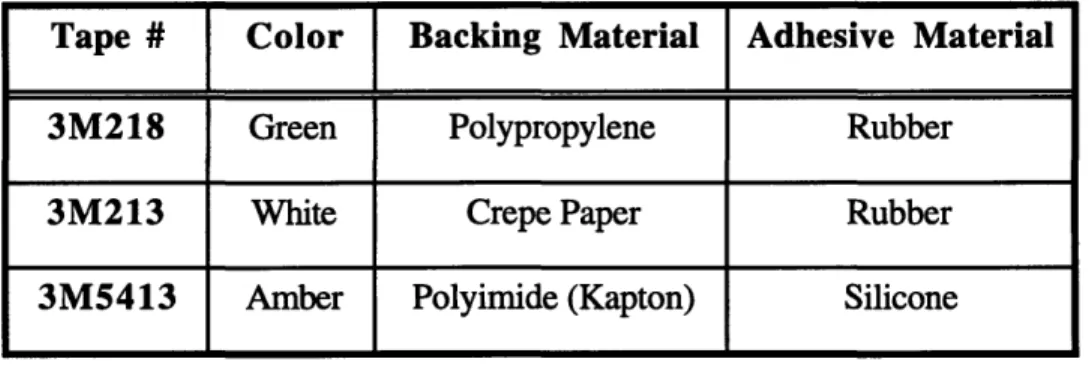
Three different types (Table 2.1) of masking tape were used for the masking step and they each had their own disadvantages. For example, the Kapton tape had a silicone adhesive which is a contaminant. The green 3M218 tape had adhesion problems and needed another tape to hold it together. The white 3M213 tape was porous and left a residue on the CCA.
Table 2.1: Types of Tape Used for Masking CCAs
Tape # Color Backing Material Adhesive Material
3M218 Green Polypropylene Rubber
3M213 White Crepe Paper Rubber
3M5413 Amber Polyimide (Kapton) Silicone
Additionally, none of the three tapes were fully anti-static, so they did not eliminate the risk of electrostatic discharge (ESD). ESD was a main concern when CCAs were handled because some components could be damaged when exposed to ESD voltages greater than 200 volts. The act of pulling the tape from the roll would result in high ESD
voltages that would be transferred to the components when the tape was placed on the CCA. Ionizers were placed at workstations to minimize ESD but had a limited range of approximately one foot.
The properties of the tapes currently used in conformal coating follow.
Green 3M218
The 3M218 tape was used for spraying because it left a clean, straight line where the coating and the tape met. However, it had several key disadvantages. The tape would lose adhesion when heated, and in general, did not adhere well to itself. For this reason, another tape (3M213) was needed to hold it together.
White 3M213
The 3M213 tape was used for spraying in conjunction with the 3M218 tape because it had better adhesion than the 3M218 tape. However, the paper backing was porous and coating easily seeped through the paper, so it was not used for masking by itself. The 3M213 tape left a residue on the CCA when subjected to elevated temperatures.
Kapton 3M5413
The 3M5413 tape was used for the auto triple dip operation because of its solvent resistance and excellent adhesion even after being subjected to long periods of heat. The combination of the polyimide backing and the silicone adhesive make the 3M5413 tape resistant to high temperatures. Unfortunately, the silicone adhesive is also a contaminant because it causes de-wetting and poor adhesion of the coating to the CCA. This de-wetting phenomenon would be especially evident when the tape adhesive came in contact with components or other parts of the CCA that were meant to be coated.
2.6.6 Viscosity Measurements
It was important to have the correct viscosity because it determined the conformal coating thickness, which needed to be between 0.001" and 0.003". The specification for viscosity for the auto triple dip tank was a tight tolerance of 18 to 20 seconds using the
Zahn #3 cup. The specified tolerance for the manual dip tank of 15 to 18 seconds using the Zahn #4 cup was also extremely narrow and did not allow room for much measurement error. These specifications seemed unreasonable if human beings were to measure the flow through the cup, as opposed to a more precise, though expensive, machine. Additionally, most operators used the second hand of their watches to check the time of flow through the cup. This method required that the operators look back and forth between the cup and their watch in order to catch the exact moment when the coating stopped flowing through the cup and to also catch at what second this occurred on their watch. The measurement error and the variation in measurement of the viscosity between operators were unknown.
Additionally, it was discovered that a different viscosity measurement cup (Zahn #2) was recommended by the conformal coating manufacturer instead of the two that were used in the conformal coating room.
2.6.7 Standard Workstations
Another barrier towards the implementation of lean manufacturing was the difficulty in moving operators between different areas of the production line to do different tasks. All of the operators were accustomed to performing both masking and demasking at their own stations and each had their own set of personal tools. If a demasking operator had to leave (for example, for a break) it was difficult to quickly shift a masking operator to work on demasking instead, because the operator who had to do the move was not familiar with where the previous operator placed the right tools needed to do the tasks. Time was consumed looking for the tools needed.
2.6.8 Unknown Coating/Thinner Ratio
Specific and different coating to thinner ratios were used for spraying, manual dip, and auto dip, but the exact ratios that would result in a viscosity that met the specification were unknown. This led to much downtime when the manual and auto dip tanks were
cleaned and refilled with new solution because the resulting viscosity for each bath was too low. This resulted in wasted material, because some of the coating was emptied to add more pure coating to raise the viscosity. This also resulted in lost time, because dip coating could not continue until the coating viscosity fell within the specifications again. This could have been prevented by knowing the coating/thinner ratio which would result in the viscosity needed.
For spraying, the only indication of what coating/xylene ratio to use was a mark made in the spray can by an operator. If that can were to become lost or damaged, the coating/thinner ratio to use would not be known.
2.6.9 Flex Mask Residue
A pink, peelable Alpha 110 solder mask was used to mask test pins and to create a
seal around some taped connectors. During the demask step, there was a tendency for the pink flex mask to leave a residue in small holes and test pins which would be painstaking to remove. Additionally, this flex mask had fairly long cure times of up to two hours. Contacting the solder mask manufacturer revealed that this flex mask was not intended for conformal coating nor was it intended to be used at the thickness of up to 0.125" that was used in conformal coating.
2.6.10 Fitting Connectors to Auto Dip Hangers
The CCAs that were dipped by the auto triple dip method were hung vertically by hangers that were clamped to a connector at one end of the CCA. If the hanger held the CCA too loosely, the CCA would fall into the coating bath, so it was important that the hanger clamp the connector well. Operators were spending too much time fitting connectors to the auto triple dip hangers. They would either try several hangers before they found one that was not broken and that fit, or they would spend time adjusting the clips of the hanger to fit the circuit card connector.
Chapter 3
Proposed Solutions, Procedures, Results, Discussion, Conclusions
3.1 Masking Boots
3.1.1 Masking Boots: Proposed Solution
Since masking was one of the most labor-intensive steps of the coating process, masking boots were considered for a possible reduction in touch labor time. Masking boots are made from a rubbery material and are made to fit snugly over the part to be masked so that coating does not leak in. Touch labor time could be reduced because rather than performing the tedious process of applying tape layer by layer, the boots could just be slipped on. The masking boots were considered for both connectors and edges.
3.1.2 Masking Boots: Procedure
In order to see if masking boots were feasible, masking boot vendors needed to be contacted in order to find out pricing and availability. It was necessary to perform a cost estimate and investigate the time saved by using boots. Specific connectors or edges needed to be chosen for trial use of the boots and the quantity of each type of boot to purchase needed to be determined. Another division of AlliedSignal used masking boots for their conformal coating operations so their use of masking boots was studied for comparison.
3.1.3 Masking Boots: Results
After contacting several masking boot vendors, it was found that the masking boots would have to be custom-made for each type of connector or edge; this involved a high tooling cost. The option of masking boots for the edges was abandoned because circuit card edges varied widely in thickness and length.
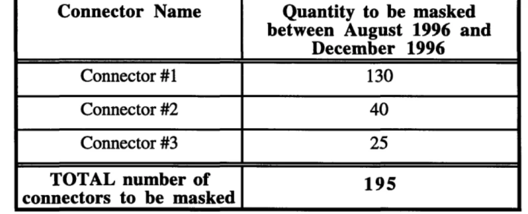
Attention was then turned to the connectors. The top ten most frequently used connectors on the CCAs of ground support test systems were investigated as possible candidates for trial use of the boots. It was found that only the top three connectors would be used in significant quantities between August and December of 1996 (Table 3.1).
Table 3.1: Top Three Most Common Ground Support Test Systems Connectors
Connector Name
Quantity to be masked
between August 1996 and
December 1996 Connector #1 130 Connector #2 40 Connector #3 25 TOTAL number of 195 connectors to be masked
3.1.3.1 Masking Boot Cost Estimate
After contacting several vendors, the smallest minimum order requirement found was 25 boots. Therefore, for each of the top three connectors, a total of 75 boots needed to be purchased at a cost of $4 per boot. This would cost a total of $300 plus a $400, first-time tooling cost for the three boots combined, resulting in a total cost of $700 for the purchase of 75 boots for three different types of connectors.
3.1.3.2 Cost Savings and Usage
By using the boots instead of tape, an optimistic estimate of the time saved was 10
minutes per boot. For the total of 195 connectors that would be masked by using boots between August 1996 and December 1996, this projected a total labor time savings of 32.5 hours. At the current cost of labor, $17.35 per hour, the savings resulting from selecting boots over tape would be $536.88.
As shown above, the difference between the cost to purchase boots, $700, and the money saved, $536.88, projected no cost savings for the estimated time saved.
3.1.4 Masking Boots: Discussion
Two things limited the feasibility of using boots. First, a masking boot would not create a perfect seal that would prevent the coating from leaking in if the CCA was submerged in the coating for dipping applications. Since this meant that the masking boots would only work well on sprayed CCAs, the volume of dipped CCAs versus sprayed CCAs were considered. A majority of the ground support test systems CCAs were manually dipped.
Also, the most significant bottlenecks of the masking step did not occur from the most commonly used connectors. They either occurred from awkward connectors that were not common enough to warrant a boot or were from connectors that had a configuration and geometry that would not allow it to be sealed well by a boot, for instance, because of the need to mask around leads.
A comparison was made with conformal coating operations at the other AlliedSignal site. Masking boots were only purchased in quantities of at least one thousand for high volume jobs, which were primarily coated by spraying. As shown in Table 3.1, the volumes dealt with in this project were much lower, also with a lower percentage of
Additionally, with the continually changing programs over the years, it did not make sense to purchase a set of boots for just one program that would be finished soon. In the end, the cost estimate revealed that the quantity of each of the top connectors (from August 1996 through the end of 1996) was too low to justify the purchase of the masking boots, and the time saved would be insignificant. It would not be cost effective for the large variety of CCAs masked.
3.1.5 Masking Boots: Conclusion
By studying the quantity of the most common connectors that needed to be masked,
the time and money saved by buying boots, the connectors that were time-consuming to mask, and the percentage of CCAs that were sprayed, the purchase of boots could not be justified.
3.2
Long Bake Cycles
3.2.1 Long Bake Cycles: Proposed Solution
Eliminating or reducing the pre-bake time was investigated for a possible reduction in cycle time. This would save between 0.5 - 2 hours of cycle time.
3.2.2 Long Bake Cycles: Procedure
In order to decide whether or not reduction of the pre-bake time would be possible, consultants were contacted for advice. Previous data from pre-bake experiments were found and studied, and pre-bake conditions were benchmarked against other conformal coating sites.
3.2.3 Long Bake Cycles: Results
It was found that the variables for baking include temperature, duration, and type of oven (convection or vacuum) used. Extent of moisture removal also depends on the
material of the printed wiring board; in general, two types of PWBs were used at this site, epoxy glass and polyimide. Polyimide PWBs retain more water, so more baking needs to be done to remove moisture. The PWBs that were coated with acrylic were made of epoxy glass. Generally, the fastest and maximum moisture removal can be achieved by using higher temperatures, longer times and a vacuum oven.
It was found that the consequences of not baking enough included measling, loss of electrical integrity which results in shorting and dendrite growth after the application of electricity (contaminants react with each other), and loss of conformal coating adhesion. The minimum required baking time depends on the soldermask, thickness and number of
layers of the epoxy board, and the number of components on the CCA.
3.2.4 Long Bake Cycles: Discussion
The idea of eliminating the moisture removal pre-bake was abandoned because this pre-bake step was widely regarded as necessary. Other compared sites were found to have more stringent pre-bake requirements such as longer times, higher temperatures, and required use of vacuum ovens. For example, one site required a 200"F pre-bake for four hours. A shorter duration pre-bake was allowed only if the CCAs were baked in a vacuum oven. The experimenters of an earlier weight loss test recommended a pre-bake at 200"F for 4 to 8 hours.
3.2.5 Long Bake Cycles: Conclusion
The current pre-bake was typical or less than other sites that also coated circuit cards. Therefore, it was determined that the pre-bake time would not be changed, although the temperature may be changed later in order to standardize the baking steps.
3.3 Standardization of the Oven Temperatures
3.3.1 Standardization of the Oven Temperatures: Proposed Solution
The goal was to determine whether standardizing the oven temperatures to one single temperature for all programs coated with acrylic was possible, and to execute the change if possible.
3.3.2 Standardization of the Oven Temperatures: Results
After speaking with people who had worked with the conformal coating process during earlier years, the origin of the two different temperatures could only be identified as the result of the consolidation of two different divisions of the company.
The only reason that could be found for not changing all of the temperatures to 170"F was a concern that an increase in temperature would damage the CCAs. However, this was unlikely since many CCAs were already baked at 170"F. If given the choice between 150"F and 170*F, 170"F would be preferable because it was a slightly higher temperature which would cause small increase in removal rate of moisture. It was also the temperature recommended by the conformal coating manufacturer.
3.3.3 Standardization of the Oven Temperatures: Discussion
While no detrimental effects to the product or process as a result of standardizing all of the temperatures to 150"F or 170"F could be identified, the cost and time to change all of the documentation to reflect the new temperature was a barrier. Since there were more programs that used the 150'F temperature than 170"F, there were more documents that reflected the 150"F temperature. Therefore, the cost to implement 150'F as the standard bake temperature would be lower than the cost to standardize the oven temperatures to
3.3.4 Standardization of the Oven Temperatures: Conclusion
It was decided that the standardization to 150"F would be implemented when many of the documents needed to be modified for some other reason, in order to reduce the cost of changing the documentation.
3.4 Long Cure Times
3.4.1 Long Cure Times: Proposed Solution
Reducing both the air cure and the oven cure from 2 hours to 30 minutes for the auto triple dip procedure was investigated. This would result in a cycle time reduction of three hours and a standardized curing step across all programs.
3.4.2 Long Cure Times: Procedure
It was revealed that the extent of cure could be found by measuring the weight loss of solvent evaporated over time from the coating on the CCAs, so weight loss tests were performed to ensure a sufficient cure for the shorter proposed times. There was also a concern that shortening the air dry would result in bubbles in the coating during the oven bake. To address this concern, experiments were performed to find what duration of air dry was necessary to prevent bubbles in the coating.
3.4.2.1 Long Cure Times: Experimental Setup of Weight Loss Test
As discussed earlier, different sources (current Manufacturing Instructions (MI), manufacturer's recommendations, and engineering instructions) suggested different cure times for the auto triple dip procedure. Therefore, the purpose of this experiment was to find the shortest acceptable air cure and oven cure for the auto triple dip method.
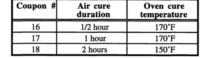
Weight loss was measured over time (Appendix B) on 3 thin stainless steel 1.5" by 2" coupons. The conditions of the cure for each coupon are listed in Table 3.2. A 170'F temperature was chosen because it was originally thought that the oven temperatures would
be standardized to 1700F. Coupon #18 was used as a benchmark of the current process. The coupons were baked in an oven for 10 days, with weight measured at different times throughout the 10 days. The experiments were run on the production floor in the same environment and with the same convection ovens as those used for the production CCAs.
Table 3.2: Air Cure and Oven Cure Conditions for the Weight Loss Test
Coupon #
Air cure
Oven cure
duration temperature
16 1/2 hour 170"F
17 1 hour 170"F
18 2 hours 150"F
The coupons were individually hung by a wire hook from a Mettler Balance (160 g maximum) during weight measurements so that the wet coating would not come in contact with the balance. All weight measurements included the weight of the coupon, hook, and the coating. The percent solvent evaporation was calculated by
% solvent evaporation = (W -Wb)/(We -Wb) (1)
where W was the weight of the coupon, hook and coating at a given time, Wb was the first weight measured after the coupon was removed from the coating, and We was the last weight measurement taken at 10 days.
The room humidity and temperature were 43% RH and 720F, respectively. The viscosity (average of 3 measurements) of the coating in the auto dip tank using the Zahn #3 cup was measured to be 19 seconds. These measurements were taken just prior to the beginning of the first cycle of the auto dip machine for these coupons. Time was recorded and measured in terms of the amount of time elapsed after the coupon had been removed from the coating bath after the third dip.
3.4.3 Long Cure Times: Results
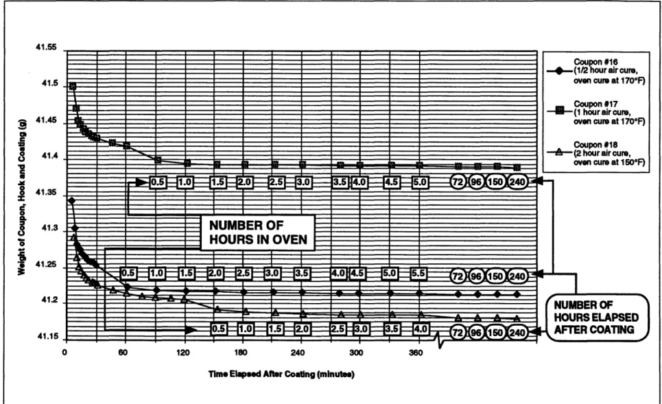
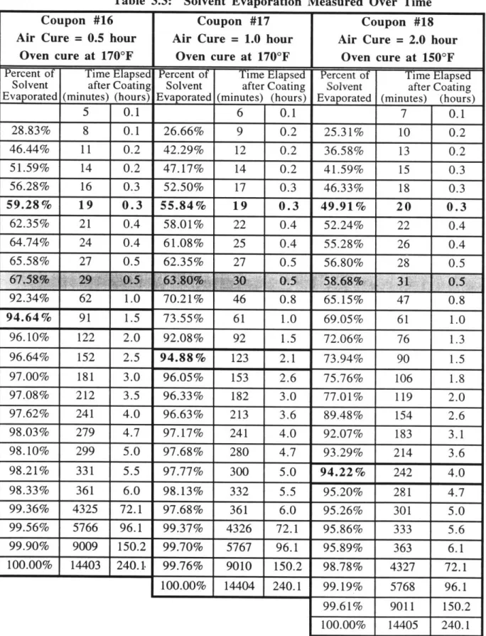
The results of the weight loss test are displayed in Figure 3.1 and Table 3.3. By comparing the results of Coupon #16 with the results of Coupons #17 and #18 in Figure 3.1, an extended air dry beyond 30 minutes did not contribute as much to the rate of drying as an oven bake would. The 2 hour air dry of Coupon #18 only seemed to prolong the evaporation of the solvent and did not seem to add anything beneficial to the solvent removal process.
Scrap CCAs that underwent the same processing conditions as Coupons #16 and #17, but subjected to an oven bake of only one hour, were compared to production CCAs that were processed under the current 2 hour air cure and 2 hour oven cure at 150"F. A visual inspection revealed that there was no difference in the number or size of bubbles in the coating between the current process and the condition of Coupons #16 and #17. Additionally, the bubbles were small enough not to be considered defects.
No information could be found on the minimum percent solvent evaporation that would be acceptable before the coated CCA could safely continue in the remaining manufacturing steps. Therefore, the current process of 2 hours air dry and 2 hours oven bake at 150"F (Coupon #18) was used as a preliminary guideline. The data show (Table 3.3) that after 2 hours of air dry and 2 hours of oven bake at 150"F, Coupon #18 achieved 94.22% solvent evaporation. By comparison, Coupon #17 appeared to have attained a similar 94.88% solvent evaporation after a 1 hour air dry and a 1 hour oven cure at 170'F, while Coupon #16 appeared to have achieved 94.64% solvent evaporation after a half hour air dry and a 1 hour oven cure at 170"F.
41.55 41.5 41.45 41.4
41.3
0
* 41.25 41.2 41.15 0 60 120 180 240Time Elapsed After Coating (minutes)
Figure 3.1. Comparing Weight Loss of Different Air Cure Times
Table 3.3: Solvent Evaporation Measured Over Time
Coupon #16 Coupon #17 Coupon #18
Air Cure = 0.5 hour Air Cure = 1.0 hour Air Cure = 2.0 hour
Oven cure at 170oF Oven cure at 170OF Oven cure at 1500F
Percent of Time Elapsed Percent of Time Elapsed Percent of Time Elapsed Solvent after Coating Solvent after Coating Solvent after Coating Evaporated (minutes) (hours) Evaporated (minutes) (hours) Evaporated (minutes) (hours)
5 0.1 6 0.1 7 0.1 28.83% 8 0.1 26.66% 9 0.2 25.31% 10 0.2 46.44% 11 0.2 42.29% 12 0.2 36.58% 13 0.2 51.59% 14 0.2 47.17% 14 0.2 41.59% 15 0.3 56.28% 16 0.3 52.50% 17 0.3 46.33% 18 0.3 59.28% 19 0.3 55.84% 19 0.3 49.91% 20 0.3 62.35% 21 0.4 58.01% 22 0.4 52.24% 22 0.4 64.74% 24 0.4 61.08% 25 0.4 55.28% 26 0.4 65.58% 27 0.5 62.35% 27 0.5 56.80% 28 01' Y..34•/0 OLZ .U 94.64% 91 1.5 96.10% 122 2.0 96.64% 152 2.5 97.00% 181 3.0 97.08% 212 3.5 97.62% 241 4.0 98.03% 279 4.7 98.10% 299 5.0 98.21% 331 5.5 98.33% 361 6.0 99.36% 4325 72.1 99.56% 5766 96.1 99.90% 9009 150.2 100.00% 14403 240.1. /IU.Z o 73.55% 92.08% 94.88% 96.05% 96.33% 96.63% 97.17% 97.68% 97.77% 98.13% 97.68% 99.37% 99.70% 99.76% 100.00% 14405 40 61 92 123 153 182 213 241 280 300 332 361 4326 5767 9010 14404 U.ts 1.0 1.5 2.1 2.6 3.0 3.6 4.0 4.7 5.0 5.5 6.0 72.1 96.1 150.2 240.1 47 61 76 90 106 119 154 183 214 242 281 301 333 363 4327 0.8 1.0 1.3 1.5 1.8 2.0 2.6 3.1 3.6 4.0 4.7 5.0 5.6 6.1 72.1 03.13%/o 69.05% 72.06% 73.94% 75.76% 77.01% 89.48% 92.07% 93.29% 94.22% 95.20% 95.26% 95.86% 95.89% 98.78% 99.19% 99.61% _ ___ _ I_ _ _ __ s _ II _:_ __ ___ ______ _____ C _ _ _ _ I 100.00% 240.1 5768 96.1 9011 150.2
3.4.4 Long Cure Times: Discussion
Since it was physically impossible for one person to measure the starting weights
(Wb) and all other weights simultaneously for all three coupons, the starting weight of
Coupon #16 was taken 5 minutes after the coupon was removed from the coating, whereas Coupon #18 was not first weighed until 7 minutes after being removed from the coating. This resulted in a lower starting weight for Coupon #18 because the coating was evaporating at a high rate and the weights were changing rapidly during the first few minutes of air drying. If the starting weight of each of the coupons had been taken at the same time, then during the first 30 minutes of air drying, all 3 coupons should have had the same extent of solvent evaporation. However, it is evident from Table 3.3 that the percentage of solvent loss was not the same for each coupon during the first 30 minutes. For example at 19-20 minutes, the percent weight loss between the three coupons showed an approximate 3.4% to 5.9% difference between Coupons #16 and #17, and Coupons
#17 and #18, respectively. This made the percentages in Table 3.3 difficult to compare.
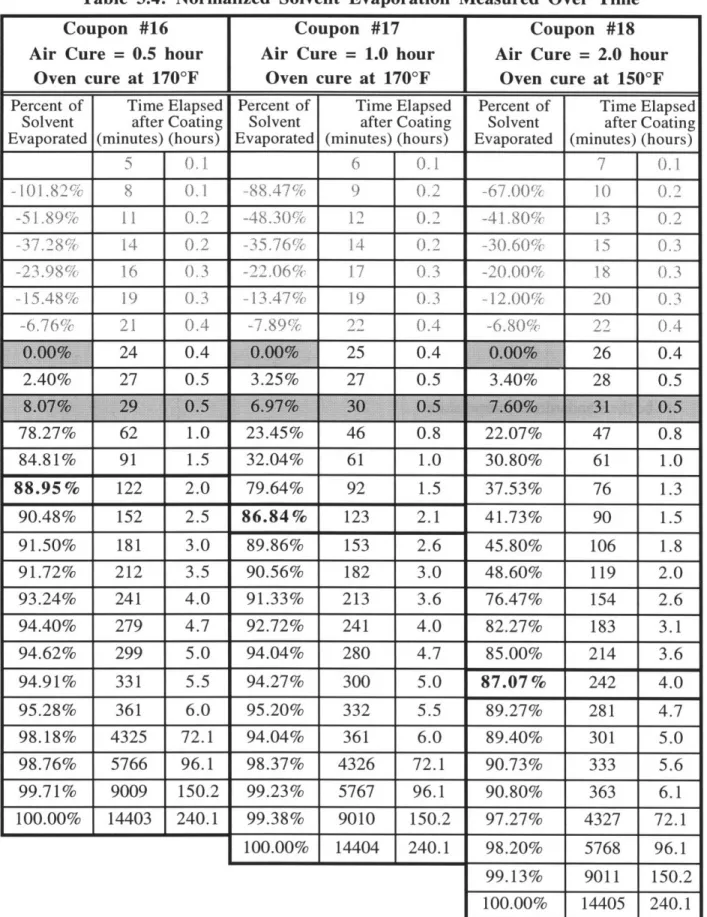
An attempt was made to make the percentages more suitable for comparison by choosing a starting point when the weights would not be changing as rapidly from minute to minute. Therefore, instead of choosing the starting point to be between 5 and 7 minutes for all 3 of the coupons (as was done for Table 3.3), a starting point of about 25 minutes was chosen so that the differences between the weight of Coupon #16 measured at 24 minutes and the weight of Coupon #18 measured at 26 minutes would be smaller than the difference at 5 to 7 minutes. The results are given in Table 3.4.
At 30 minutes, when there should have been no difference in percent solvent evaporation between the coupons, the greatest difference was 1.10% between Coupon #16 and Coupon #17. At 60 minutes, when the percent solvent evaporation should have been the same between Coupon #17 and Coupon #18, the difference measured was 1.24%. Both of these differences between coupons are lower than any of the differences given in
Table 3.3, making it more appropriate to compare the percent solvent evaporation between coupons.
From Table 3.4, in order to achieve a similar extent of cure of 87.07% as the current process (Coupon #18), a half hour air dry and 1.5 hour oven bake at 170"F would be necessary for Coupon #16 (resulting in 88.95% solvent evaporation), and a 1 hour air dry and 1 hour oven bake at 170"F would be required for Coupon #17 (resulting in 86.84% solvent evaporation).
These results did not point to the possibility of reducing the oven cure to a half hour if the 2 hour air dry and 2 hour oven bake at 150"F was used as a guideline in terms of minimum required extent of cure. However, this guideline was not necessarily correct or incorrect. Additionally further weight loss tests needed to be run at 150"F if it was chosen to be the standardized temperature.
Table 3.4: Normalized Solvent Evaporation Measured Over Time
Coupon #16 Coupon #17 Coupon #18
Air Cure = 0.5 hour Air Cure = 1.0 hour Air Cure = 2.0 hour Oven cure at 170'F Oven cure at 170'F Oven cure at 150'F
Percent of Time Elapsed Percent of Time Elapsed Percent of Time Elapsed
Solvent after Coating Solvent after Coating Solvent after Coating
Evaporated (minutes) (hours) Evaporated (minutes) (hours) Evaporated (minutes) (hours)
5 .I. 6 0. 7 0.1 -101. 82% 8 0.1 -88.47 9 0,2 -67.00% 10 0.,2 -51.89% 1.1 0.2 -48.30% 12 0. -41.80 13 0 2 -3.7.28% 14 0.2 -35.76% 14 0.2 -30,60% 15 0.3 -23.98% 16 16 3 -2206 -2.6 17 0,.3 -20.00% 18 0.3 -15.48% 19 0.3 -13,47% 19 0.3 -12.00% 20 0.3 -6.76% 21 0.4 -7.89% 22 0.4 -6.80', 22 0.4 I 2.40% | 27 0.5 3.23% 27 0.5 I 3.40% | 28 0.5 78.27% 62 1.0 84.81% 91 1.5 88.95% 122 2.0 90.48% 152 2.5 91.50% 181 3.0 91.72% 212 3.5 93.24% 241 4.0 94.40% 279 4.7 94.62% 299 5.0 94.91% 331 5.5 95.28% 361 6.0 98.18% 4325 72.1 98.76% 5766 96.1 99.71% 9009 150.2 100.00% 14403 240.1 22.07% 30.80% 37.53% 41.73% 45.80% 48.60% 76.47% 82.27% 85.00% 87.07% 89.27% 89.40% 90.73% 90.80% 97.27% 47 61 76 90 106 119 154 183 214 242 281 301 333 363 4327 0.8 1.0 1.3 1.5 1.8 2.0 2.6 3.1 3.6 4.0 4.7 5.0 5.6 6.1 72.1 98.20% 99.13% 9011 100.00% 150.2 240.1 23.45% 32.04% 79.64% 86.84% 89.86% 90.56% 91.33% 92.72% 94.04% 94.27% 95.20% 94.04% 98.37% 99.23% 99.38% 100.00% 46 61 92 123 153 182 213 241 280 300 332 361 4326 5767 9010 14404 0.8 1.0 1.5 2.1 2.6 3.0 3.6 4.0 4.7 5.0 5.5 6.0 72.1 96.1 150.2 240.1 -·;·;;---e - ---- -n c - ~u I- _-L -~I~ _ 24 0.4 25 0.4 26 0.4 14405 5768 96.1
3.4.5 Long Cure Times: Conclusion
The only possible reason that could be found for the 2 hour air cure was a concern that heating the CCA too quickly would cause bubbles to form. However, no evidence of a bubble problem could be found with a minimum 30 minute air cure. Since the period of air dry after 30 minutes did not contribute as much to the rate of drying as an oven bake, it would be beneficial to dry the CCA in an oven after the 30 minute air dry to increase the rate of solvent evaporation. The Materials Laboratory approved the proposal of shortening the air dry to 30 minutes for the auto triple dip method, resulting an a cycle time reduction of 1.5 hours.
Although it seemed unnecessary to have a two hour oven bake when the engineering specifications and the manufacturer did not require these longer curing times, inconclusive results on the shortening of the oven bake to 30 minutes necessitate additional tests, discussed in Future Work.
3.5 Standardization of the Masking Tapes
3.5.1 Standardization of the Masking Tapes: Proposed Solution and
Procedure
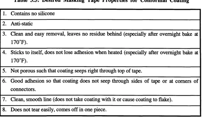
Since each of the three masking tapes that were being used had several disadvantages, the goal was to replace the three tapes with one tape that incorporated all of the desired properties. These properties are listed in Table 3.5.
Table 3.5: Desired Masking Tape Properties for Conformal Coating 1. Contains no silicone
2. Anti-static
3. Clean and easy removal, leaves no residue behind (especially after overnight bake at 170"F).
4. Sticks to itself, does not lose adhesion when heated (especially after overnight bake at 170"F).
5. Not porous such that coating seeps right through top of tape.
6. Good adhesion so that coating does not seep through sides of tape or at corners of connectors.
7. Clean, smooth line (does not take coating with it or cause coating to flake). 8. Does not tear easily, comes off in one piece.
An anti-static tape was desired because it would eliminate any possible risk of ESD damage caused by the tape. Good adhesion was necessary so that the coating would not seep through sides of tape or at corners of connectors to require extra touch-up. Some tapes were so thick that when the tape was removed, it would cause the coating adjacent to it to be removed or to flake which was undesirable. In the interests of minimizing labor time, the tape needed to be easy to remove during the demasking step. Several tapes (Table 3.6) were investigated and tested by both applying the tape to a bare PWB (no components) and by masking scrap CCAs with the tape. Each of the qualities in Table 3.5 were studied.
Table 3.6: Masking Tapes Tested
Tape Backing Material Adhesive Material
HumiSeal HT500 polyethylene teraphthalate (PET) Rubber
3M1205 (Kapton) Polyimide Acrylic
3M42 Polyimide Acrylic
3.5.2 Standardization of the Masking Tapes: Results
Of the tapes investigated and tested none met all of the requirements imposed.
Results are displayed in Table 3.7.
Table 3.7: Results of Alternate Tapes Tested
Tape Desirable Undesirable Qualities
Qualities
HumiSeal HT500 Good adhesion, Not anti-static
clean line
3M1205 (Kapton) none Tore too easily, left extensive residue
3M42 Anti-static Tore too easily, left some residue, poor adhesion when exposed to heat
3M40 Anti-static Residue
The HumiSeal HT500 tape did not have any major disadvantages, however it was not anti-static. Other tapes such as the Acrylic Kapton 3M1205 and the 3M40 tapes left a residue and were not anti-static.
The most promising tape candidate was the 3M42 tape because it was anti-static, contained no silicone, and left a straight edge in the coating. However, it had a few shortcomings that prevented full use on the conformal coating line. The 3M42 tape left a residue on black anodized surfaces which was unacceptable. Over time, the tape would also lose adhesion when left in air or in an oven. It was difficult to quickly lift the end of the coated tape for demasking which would only increase the touch labor time. The tape was too weak and ripped easily. It also did not adhere well enough for awkward, hard-to-reach components. In these cases, the operators needed to resort to the currently used Kapton 3M5413 tape with the silicone-based adhesive.