Publisher’s version / Version de l'éditeur:
Vous avez des questions? Nous pouvons vous aider. Pour communiquer directement avec un auteur, consultez la
première page de la revue dans laquelle son article a été publié afin de trouver ses coordonnées. Si vous n’arrivez pas à les repérer, communiquez avec nous à [email protected].
Questions? Contact the NRC Publications Archive team at
[email protected]. If you wish to email the authors directly, please see the first page of the publication for their contact information.
https://publications-cnrc.canada.ca/fra/droits
L’accès à ce site Web et l’utilisation de son contenu sont assujettis aux conditions présentées dans le site
LISEZ CES CONDITIONS ATTENTIVEMENT AVANT D’UTILISER CE SITE WEB.
59th Annual Conference of the Western Canada Water and Wastewater Association [Proceedings], p. 12, 2007-10-23
READ THESE TERMS AND CONDITIONS CAREFULLY BEFORE USING THIS WEBSITE.
https://nrc-publications.canada.ca/eng/copyright
NRC Publications Archive Record / Notice des Archives des publications du CNRC :
https://nrc-publications.canada.ca/eng/view/object/?id=0a68ae1d-a657-403b-b1a7-6e469d550ff3 https://publications-cnrc.canada.ca/fra/voir/objet/?id=0a68ae1d-a657-403b-b1a7-6e469d550ff3
NRC Publications Archive
Archives des publications du CNRC
This publication could be one of several versions: author’s original, accepted manuscript or the publisher’s version. / La version de cette publication peut être l’une des suivantes : la version prépublication de l’auteur, la version acceptée du manuscrit ou la version de l’éditeur.
Access and use of this website and the material on it are subject to the Terms and Conditions set forth at
Feasibility of two technologies for detecting leaks in wastewater forcemains
http://irc.nrc-cnrc.gc.ca
Fe a sibilit y of t w o t e chnologie s
for de t e c t ing le a k s in
w a st e w at e r forc e m a ins
N R C C - 5 0 3 0 5
D a r r e n Y a r e c h e w s k i , O s a m a H u n a i d i , C h r i s
M a c e y , a n d K a s Z u r e k
2 0 0 7 - 1 0 - 2 3
A version of this document is published in / Une version de ce document se trouve dans: 59th Annual Conference of the Western Canada Water and Wastewater Association (Edmonton, Alta., October 23, 2007)
The material in this document is covered by the provisions of the Copyright Act, by Canadian laws, policies, regulations and international agreements. Such provisions serve to identify the information source and, in specific instances, to prohibit reproduction of materials without written permission. For more information visit http://laws.justice.gc.ca/en/showtdm/cs/C-42
Les renseignements dans ce document sont protégés par la Loi sur le droit d'auteur, par les lois, les politiques et les règlements du Canada et des accords internationaux. Ces dispositions permettent d'identifier la source de l'information et, dans certains cas, d'interdire la copie de documents sans permission écrite. Pour obtenir de plus amples renseignements : http://lois.justice.gc.ca/fr/showtdm/cs/C-42
Environmental Excellence 59th Annual Conference of the
Western Canada
Water and Wastewater Association Edmonton, Alberta
October 23-26, 2007
FEASIBILITY OF TWO TECHNOLOGIES FOR DETECTING LEAKS IN WASTEWATER FORCEMAINS
Darren Yarechewski1, Osama Hunaidi2, Chris Macey1, and Kas Zurek3
1
UMA-AECOM, Community Infrastructure Sector, Winnipeg, MB
2
National Research Council Canada, Institute for Research in Construction, Ottawa, ON
3
City of Winnipeg, Water and Waste Department, Winnipeg, MB
ABSTRACT
This paper presents the results of a field study undertaken recently to investigate two leak detection technologies for wastewater forcemains in Winnipeg, Manitoba. The first technology was based on the detection and analysis of acoustic leak noise, and the second was based on simultaneous measurement of inflow and outflow using magnetic flow meter technology. Both technologies were found to be viable for detecting leakage in wastewater forcemains. The acoustic technology requires little hardware that’s relatively inexpensive and that can be installed without taking forcemains out of service. However, the magnetic flow meter technology is expensive and its installation is intrusive, laborious, and risky.
INTRODUCTION
Fifty-six wastewater river crossings exist in the City of Winnipeg inventory, categorized as gravity sewers, inverted siphons, and forcemains (pipes under pressure) where forcemains are either mounted on a bridge or buried beneath the river. Leak detection is needed to safeguard the river environment from inadvertent wastewater flow from potential leaks at river crossings. While there are numerous technologies that have been developed to facilitate both periodic and continuous monitoring of leakage from pressurized water distribution pipes, the successful application of these technologies for forcemains has not been previously demonstrated. A field study was undertaken to investigate two leak detection technologies that are commercially available for wastewater forcemains.
Field trials were conducted in Winnipeg, MB, during summer and fall 2006 on an in-service 450mm diameter PVC forcemain. Trials were conducted for: (i) an acoustic technology for direct detection of single leakage events, and (ii) magnetic flow measurement technology to detect leakage indirectly with continuous flow monitoring. The study was performed by UMA-AECOM for the City of Winnipeg in collaboration with the National Research Council Canada.
The acoustic method is currently available in portable form for manual detection of existing leaks but it requires software and electronic development for continuous monitoring. It requires little hardware that’s relatively inexpensive and can be installed without taking forcemains out of service. However, the magnetic meter technology is expensive and its installation is intrusive, laborious, and risky.
In this paper, findings based on the fieldwork carried out in Winnipeg are presented and discussed. Details of field tests; instrumentation and software; measurement and analysis procedures are also presented.
DESCRIPTION OF LEAK DETECTION METHODS Acoustic Technology – Direct Method
Acoustic technology used in the tests was the LeakfinderRT system developed jointly by the National Research Council Canada and Echologics Inc., of Toronto, ON. This technology is based on leak noise correlation and is widely used for locating leaks in municipal water distribution/transmission pipes. It has not been used on sewermains for continuous monitoring but single event leak detection looks promising based on success in watermain applications. This method is considered direct because the noise characteristics of the leak are directly used to detect and locate the leak.
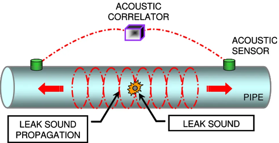
Sensors are placed at opposite ends of the pipe to be monitored. In the case of a forcemain river crossing, sensors would be installed at opposite shores and the pipe located beneath the river would be the monitored section as shown in Figure 1. Acoustic noise correlation works as follows. Sensors pick up leak-induced noise signals, wireless transmitters broadcast those signals, and a wireless receiver picks up the broadcast. A computer records leak noise signals, then it automatically pinpoints the leak based on the time delay between leak signals, acoustic velocity in the pipe, and distance between sensors. Acoustic velocity is a known property of the pipe and sensor spacing can be found from drawings or physically measured. The time delay is determined by cross-correlating leak signals. In the presence of a leak, the correlation function displays a clear peak at the time delay between leak signals.
Factors that affect successful detection of leak sound include internal pressure of the pipe, distance of the sensors from the leak, and the pipe material. Higher pipe pressures result in greater leak sound resulting from turbulent flow as fluid escapes from the internal pipe pressure to atmospheric pressure. A pressure of 138 kPa is typically required for leak detection. In terms of distance, the farther the sensor from the leak
source the more the leak sound will degrade to the point where the sound will become undetectable. Metallic pipes are better sound transmitters than plastic pipes because the material is denser. The tendency for the relatively “soft” material of plastic pipes is to absorb rather than to transmit sound.
Magmeter Technology – Indirect Method
Magmeter technology and accuracy is well developed in industrial and municipal applications. This is considered an indirect method because the difference in flows is used to infer that a leak exists, without locating the leak directly. Two flow measurements from opposite sides of the river are used for comparison as shown in Figure 2. Magmeter technology uses magnetic principles to measure flow velocity.
ACOUSTIC TECHNOLOGY TRIAL Test Setup
The philosophy of this trial (Figure 3) was to use a test setup that resembles actual conditions and at the same time allow an evaluation of the effect of several factors such as leak size, sensor type and spacing, etc. To do this an artificial leak was created through a tap in an in-service 450mm diameter PVC forcemain. Since it is not practical to expose the pipe at an actual river crossing at several locations, a site was chosen that is entirely within dry land, and subsequently this trial is designated “Dry Land Trial”. The maximum spacing of the sensors is a straight distance of about 300m, which is representative of the widest river crossing in Winnipeg, which is on the Red River. If the acoustic method succeeds in detecting leakage over a 300m span, then it will also succeed over shorter spans. Also, if the method succeeds in detecting leakage in the selected PVC pipe, which has a higher degree of sound attenuation than metallic pipes, it will also succeed for metallic pipes.
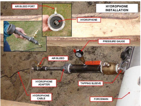
To create a variety of spacings from the acoustic sensors to the leak location, the forcemain is exposed at seven locations at 50m intervals. Saddle taps were installed at three locations with the central tap used to create the artificial leak (with flow measured by a magmeter before it’s discharged to a wastewater manhole). The other two taps bracketing the leak were used to install hydrophones. At the remaining four locations, the top of the pipe was exposed and 50mm square steel plates were glued to the top of the pipe to allow attachment of geophones and accelerometers using magnets. Hydrophones are in contact with the wastewater (Figure 4) and detect leak sounds propagating through the fluid core. Geophones and accelerometers are installed on the pipe’s exterior to detect vibration propagating through the pipe wall.
-ACOUSTIC SENSOR ACOUSTIC CORRELATOR PIPE LEAK SOUND LEAK SOUND PROPAGATION ACOUSTIC SENSOR ACOUSTIC CORRELATOR PIPE LEAK SOUND LEAK SOUND PROPAGATION
Figure 1 Schematic of Acoustic Method
DIFFERENTIAL FLOW CALCULATION OUTFLOW MAGMETER INFLOW MAGMETER PIPE INFLOW OUTFLOW LEAK FLOW DIFFERENTIAL FLOW CALCULATION OUTFLOW MAGMETER INFLOW MAGMETER PIPE INFLOW OUTFLOW LEAK FLOW
Figure 2 Schematic of Magmeter Method
MAIN FLOW LEAK FLOW
NOTE: ACTUAL DISTANCES IN BRACKETS
0m REFERENCE POINT 50m (30.0) 100m (85.8) 200m (186.2) 250m (233.5) 300m (283.9) 150m (141.0) 50m (46.4) PUMPING STATION HYDROPHONE PRESSURE GAUGE VIBRATION SENSORS
LEAK GATE VALVE
TO COMBINED SEWER MANHOLE MAGMETER TEST SETUP HYDROPHONE MAIN FLOW LEAK FLOW
NOTE: ACTUAL DISTANCES IN BRACKETS
0m REFERENCE POINT 50m (30.0) 100m (85.8) 200m (186.2) 250m (233.5) 300m (283.9) 150m (141.0) 50m (46.4) 0m REFERENCE POINT 50m (30.0) 100m (85.8) 200m (186.2) 250m (233.5) 300m (283.9) 150m (141.0) 50m (46.4) PUMPING STATION HYDROPHONE PRESSURE GAUGE VIBRATION SENSORS
LEAK GATE VALVE
TO COMBINED SEWER MANHOLE
MAGMETER
TEST SETUP
HYDROPHONE
Figure 4 Hydrophone Installation
Test Program
Testing was conducted for 5 days in the summer of 2006. The traditional method for acoustic correlation is to attempt leak correlation with the maximum positive internal pressure (pumps are on) to create the most audible leak sound. It was soon learned during the tests that the pump sound overpowers the sensors and effectively masks the leak sound, resulting in leak detection only being possible when the pumps are off.
Two streams of data were collected during the Dry Land Trial and include acoustic correlation data and magmeter leak flow data. Correlation software was used to collect data from the acoustic sensors for different test conditions. Each test attempts to obtain correlation of a leak sound located between two acoustic sensors (a leak signal located between sensors is termed in-bracket). Data is collected over a duration of approximately 2 minutes. This short duration of leak signals was sufficient for obtaining a correlation. A total of 113 tests were performed, representing different combinations of parameters including sensor type and spacing, leak size, etc. Sensors were hydrophones, geophones or accelerometers. Spacing between sensors was between 100 and 300m. The flow rate of the leak was controlled using a 50mm gate valve with the valve open at 3 different positions during the course of the trial, corresponding to roughly 1, 3 and 5 L/s.
-Acoustic Correlation Results
Correlation of acoustic leak signals measured by two separate sensors involves comparison of the waveform (shape) of the two signals to determine the time delay between them. The computation that’s needed to do this comparison is done automatically using computer software of the LeakfinderRT system. Figure 5 shows the travel path of leak sound and pump sound. When there is correlation of two leak signals, the location of the leak can be calculated.
The correlation function (Figure 6) will show a definite peak and minimal scatter in amplitude when there is a good correlation between two leak signals. In addition, the time offset corresponding to this peak, which is automatically determined by the LeakfinderRT system, will indicate the difference in arrival time from the leak to each of the two sensors. This arrival time is used by the LeakfinderRT system to automatically establish the distance from the leak to each sensor.
The coherence function (Figure 6) provides an indication of the degree of relatedness between leak sounds, measured by the two sensors, at different frequencies. If at a particular frequency the coherence function approaches 1, then leak sounds measured at this frequency at the two sensors are related, meaning that they come from the same noise source (leak). On the other hand, a coherence function that approaches 0 means that the measured sounds are unrelated.
The content of the pipe plays a role in the travel of leak sound. A pipe filled with air will result in leak sound traveling at the speed of sound or 340 m/s but a pipe fully filled with liquid, as in this trial, would result in leak sound traveling at the speed of 440 m/s. Therefore the effect of air in a pipe is to slow down the travel velocity of sound in the pipe.
MAIN FLOW LEAK FLOW
NOTE: ACTUAL DISTANCES IN BRACKETS 0m REFERENCE POINT 50m (30.0) 100m (85.8) 200m (186.2) 250m (233.5) 300m (283.9) 150m (141.0) 50m (46.4) PUMPING STATION HYDROPHONE PRESSURE GAUGE VIBRATION SENSORS
LEAK GATE VALVE
TO COMBINED SEWER MANHOLE MAGMETER HYDROPHONE WATER FULL PIPE
IN-BRACKET: DETECT LEAK, PUMPS OFF OUT-OF-BRACKET: DETECT PUMPS, PUMPS ON
LEAK NOISE
IN-BRACKET LEAK SIGNAL TRAVEL – PUMPS OFF
OUT-OF-BRACKET SIGNAL TRAVEL - PUMPS ON
SIGNAL VELOCITY VARIES WITH NEGATIVE PRESSURE VARIATION ALONG WATER CORE MAIN FLOW LEAK FLOW
NOTE: ACTUAL DISTANCES IN BRACKETS 0m REFERENCE POINT 50m (30.0) 100m (85.8) 200m (186.2) 250m (233.5) 300m (283.9) 150m (141.0) 50m (46.4) 0m REFERENCE POINT 50m (30.0) 100m (85.8) 200m (186.2) 250m (233.5) 300m (283.9) 150m (141.0) 50m (46.4) PUMPING STATION HYDROPHONE PRESSURE GAUGE VIBRATION SENSORS
LEAK GATE VALVE
TO COMBINED SEWER MANHOLE
MAGMETER
HYDROPHONE
FULL PIPE
IN-BRACKET: DETECT LEAK, PUMPS OFF OUT-OF-BRACKET: DETECT PUMPS, PUMPS ON
LEAK NOISE
WATER IN-BRACKET LEAK SIGNAL TRAVEL – PUMPS OFF
OUT-OF-BRACKET SIGNAL TRAVEL - PUMPS ON
SIGNAL VELOCITY VARIES WITH NEGATIVE PRESSURE VARIATION ALONG WATER CORE
Figure 5 Path of Leak and Pump Sound Travel
pipe, an air pocket was forming inside the pipe during pump-off cycles. This was confirmed by successfully correlating sound at stations to which the air cavity has extended. This was the case for stations closest to the leak. However, no success was achieved in correlating sounds at stations farther from the leak, to which the air cavity did not extend.
When a rainstorm occurred on the fourth day of testing, the pipe was completely filled by both forcemain pumps running for about one hour. Subsequently, a successful acoustic correlation was achieved with air allowed to enter the pipe during the pump-off cycle. Afterward, only water was allowed to enter the pipe to prevent the air pocket formation and to reduce attenuation of leak sounds.
The effect of a full pipe is that hydrophone sensors (and to a limited extent the geophone sensors) could detect the pump sound as an out-of-bracket signal (signal not located between sensors) when the pumps are on (Figure 6) and detect the leak sound when the pumps are off as an in-bracket signal (Figure 7). This was not possible when the air cavity existed. Hydrophones were the most effective sensors for successfully correlating the leak sound for the 300m length of forcemain.
PUMPS ON OUT – OF – BRACKET PUMP SOUND HIGH COHERENCE AT 20 Hz PUMP SOUND AT 20 Hz PUMP SOUND AT 20 Hz 2ndHARMONIC OF PUMP SOUND AT 40 Hz
PEAK PUMPS ON OUT – OF – BRACKET PUMP SOUND HIGH COHERENCE AT 20 Hz PUMP SOUND AT 20 Hz PUMP SOUND AT 20 Hz 2ndHARMONIC OF PUMP SOUND AT 40 Hz
PEAK
Figure 6 Out of Bracket Detection of Forcemain Pump Sound
-PUMPS OFF IN – BRACKET
LEAK SOUND
PEAK HIGH COHERENCE
DISTANCE FROM LEAK SOUND TO SENSORS PUMPS OFF IN – BRACKET LEAK SOUND PEAK HIGH COHERENCE
DISTANCE FROM LEAK SOUND TO SENSORS
Figure 7 In Bracket Correlation of Leak Sound
When it was discovered that the leak sound could be detected when pumps are off, with air drawn into the forcemain, it was decided to simulate the condition of water being drawn into the pipe. It was believed that air rushing into the pipe creates more turbulence and subsequently louder sound at the leak than water being drawn in. A leak in a river crossing forcemain may be under either air or water, depending on whether the location where the leak occurs is at an elevation that is above or below the water table. Naturally if the leak occurs within the horizontal extent of the river channel, the pipe exterior would be below the water table and water will be drawn into the forcemain. Therefore, it was necessary to ensure that under this condition it is also technically feasible to detect leakage in the forcemain.
The leak location was quite accurately measured when the sensors were relatively close to the leak with the difference between the measured and actual distance within about 1m. These earlier correlations are under the condition when air was still allowed to enter the forcemain during the pump-off cycle. When the pipe was full and air not allowed to enter the forcemain, the accuracy of the leak location varied considerably. With sensors at the 300m maximum extent, the accuracy ranged from about 4 to 31m. The reason for this difference is considered due to the variation of negative pressure along the pipe
length.
MAGMETER TECHNOLOGY TRIAL Test Setup
The method for the magmeter trial consists of measuring a forcemain’s inflow and outflow at opposite shores of a crossing of the Red River (Figure 8). The premise is that a measured difference between the two flow measurements represents a leak from the forcemain. The forcemain is a 500mm steel pipe mounted to the underside of a bridge with 450mm PVC pipe leading to the bridge. The benefit of using this location is the visibility of the pipe and the foreknowledge that the pipe presently does not leak.
Magmeter installation is an intrusive and costly process requiring significant modifications to the existing pipe with installation of flanges, spool sections, and magmeters along with cutting and removal of an original section of pipe (Figure 9 and Figure 10). A high degree of planning is required to ensure that sewage is not spilled either to the environment or to residents’ basements during magmeter installation. Magmeters were installed where full pipe flow is assured for accurate flow measurement.
OUTFLOW MAGMETER Red River PIPE FLOW LEAK MAGMETER TO COMBINED SEWER INFLOW MAGMETER BRIDGE OUTFLOW MAGMETER OUTFLOW MAGMETER Red River PIPE FLOW Red River Red River PIPE FLOW PIPE FLOW LEAK MAGMETER TO COMBINED SEWER LEAK MAGMETER LEAK MAGMETER TO COMBINED SEWER TO COMBINED SEWER INFLOW MAGMETER INFLOW MAGMETER INFLOW MAGMETER BRIDGE
Figure 8 Magmeter Method Test Setup
-Figure 9 450mm Diameter Outflow Magmeter with Chamber Construction
Leak Test and Results
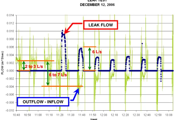
In addition to inflow and outflow comparison, an artificial leak was created to determine the size of leak flow that could be detected. A 50mm tap was welded to the underside of the steel forcemain mounted on the bridge and discharged through a 50mm magmeter to a wastewater sewer. Thus, the flows from the three magmeters can be compared where measurements from the 500mm inflow magmeter should be equal to the outflow from both the 450mm outflow magmeter and the 50mm artificial leak magmeter. The leak trial was conducted in December 2006 with useful data collected only during the first 5 pump cycles due to inflow magmeter malfunction.
Two sets of data were collected during the leak trial using two laptop computers on site. One computer was connected to the 50mm artificial leak magmeter while the second computer, equipped with a modem card, accessed the inflow and outflow magmeter data via the internet. This data is combined in the instantaneous flow plot in Figure 11.
The leak flow rates ranged from 3 to 6 L/s with the difference between the outflow and inflow magmeter measurements visibly influenced by the leak flows. As shown in Figure 11, during a leak flow of about 6 L/s the difference between the outflow and inflow is about -4 L/s (note that the negative sign indicates that the outflow is now less than the inflow). With the outflow-inflow difference immediately prior to the leak trial of about
LEAK FLOW OUTFLOW - INFLOW 6 to 7 L/s 2 to 3 L/s 6 L/s TIME LEAK FLOW OUTFLOW - INFLOW 6 to 7 L/s 2 to 3 L/s 6 L/s TIME LEAK FLOW 6 to 7 L/s 6 to 7 L/s 2 to 3 L/s 2 to 3 L/s 6 L/s 6 L/s OUTFLOW - INFLOW TIME
Figure 11 Magmeter Method Leak Test Results
-+2 to +3 L/s, the total shift in flow difference is approximated to about 6 to 7 L/s, which matches quite closely with the artificial leak flow rate of 6 L/s measured by the 50mm magmeter.
CONCLUSIONS Acoustic Technology
• Acoustic method is technically feasible for single event monitoring with manual software manipulation and data collection but it requires software and electronic development for continuous monitoring of an actual river crossing.
• A leak is detectable only when forcemain pumps are off to provide a quiet pipe environment since pump sound masks the leak sound.
• Monitoring under low negative pressure, when the pumps are off, is an unorthodox approach in the use of acoustic sensors for leak detection that was discovered to be quite effective.
• Acoustic leak detection is possible for the most limiting parameters including small leak (1.8 to 4.8 L/s), low pipe pressure (-14 to +76 kPa), long distance between sensors (300m), and plastic pipe (greater sound attenuation).
• Hydrophone sensors, in contact with the pipe fluid, provided the best correlation results as opposed to geophones and accelerometers mounted on the pipe’s exterior. • Pipes are required to be full (no air pocket) to detect leakage.
• Leak location estimated to within 1m of its true location when acoustic sensors are located 100m apart but within 4m to 31m when the sensors are 300m apart.
• Hydrophone sensors can be installed without flow interruption and with minimal requirements for room to work.
Magmeter Technology
• Leak detection is technically feasible with the magmeter method and continuous monitoring at a river crossing.
• Artificial leak flow rates ranging from 3 to 6 L/s were detected.
• Response to flow change at respective magmeter locations is instantaneous. • Data is easily interpreted.
• Installation is intrusive, laborious, expensive, and risky.
• Instantaneous flow difference of 1 L/s was measured during steady state pumping. • Scatter of instantaneous flow difference measurements, under all flow conditions,
typically ranges from -11 L/s to +12 L/s (about a 23 L/s bandwidth) with maximum range from -17 L/s to +18 L/s (35 L/s bandwidth).
• Instantaneous flow (m3
/s) preferred when comparing inflow and outflow to assess if a