Publisher’s version / Version de l'éditeur:
Vous avez des questions? Nous pouvons vous aider. Pour communiquer directement avec un auteur, consultez la
première page de la revue dans laquelle son article a été publié afin de trouver ses coordonnées. Si vous n’arrivez
Questions? Contact the NRC Publications Archive team at
[email protected]. If you wish to email the authors directly, please see the first page of the publication for their contact information.
https://publications-cnrc.canada.ca/fra/droits
L’accès à ce site Web et l’utilisation de son contenu sont assujettis aux conditions présentées dans le site LISEZ CES CONDITIONS ATTENTIVEMENT AVANT D’UTILISER CE SITE WEB.
Research Report (National Research Council of Canada. Institute for Research in Construction), 2009-10-01
READ THESE TERMS AND CONDITIONS CAREFULLY BEFORE USING THIS WEBSITE.
https://nrc-publications.canada.ca/eng/copyright
NRC Publications Archive Record / Notice des Archives des publications du CNRC :
https://nrc-publications.canada.ca/eng/view/object/?id=67cd41ba-9721-437d-929d-4f7ae8542425 https://publications-cnrc.canada.ca/fra/voir/objet/?id=67cd41ba-9721-437d-929d-4f7ae8542425 For the publisher’s version, please access the DOI link below./ Pour consulter la version de l’éditeur, utilisez le lien DOI ci-dessous.
https://doi.org/10.4224/20373910
Access and use of this website and the material on it are subject to the Terms and Conditions set forth at
A Performance-based approach for fire-resistance test of reinforced concrete columns
A Pe rfor m a nc e -ba se d a pproa ch for fire -re sist a nc e t e st of
re inforc e d c onc re t e c olum ns
I R C - R R - 2 8 7
M o s t a f a e i , H . ; M a n n a r i n o , J .
S e p t e m b e r 2 0 0 9
The material in this document is covered by the provisions of the Copyright Act, by Canadian laws, policies, regulations and international agreements. Such provisions serve to identify the information source and, in specific instances, to prohibit reproduction of materials without written permission. For more information visit http://laws.justice.gc.ca/en/showtdm/cs/C-42
Les renseignements dans ce document sont protégés par la Loi sur le droit d'auteur, par les lois, les politiques et les règlements du Canada et des accords internationaux. Ces dispositions permettent d'identifier la source de l'information et, dans certains cas, d'interdire la copie de documents sans permission écrite. Pour obtenir de plus amples renseignements : http://lois.justice.gc.ca/fr/showtdm/cs/C-42
NRC‐CNRC
A Performance-based Approach for Fire-Resistance
Test of Reinforced Concrete Columns
by H. Mostafaei, and J. Mannarino
Research Report No. 287
A Performance-based Approach for Fire-Resistance Test of Reinforced Concrete Columns
by H. Mostafaei, and J. Mannarino
ABSTRACT
This paper describes a simple performance-based approach for estimating fire-resistance of reinforced concrete columns, within a building frame, by considering the effect of the
structural system and thermal expansion phenomenon. The attempt was made to develop an analytical tool for application of the new performance-based design philosophy, using evaluation of structural performance in fire, considering the entire structural system rather than individual elements. This method describes how to determine fire performance of a reinforced concrete column when it is part of a structural frame. In this approach, the entire frame is simplified into a single equivalent spring and coupled with the column. The column is then exposed to fire and, according to the column deformation and the equivalent frame spring stiffness, the test load, restraint force, is determined. Frames with different numbers of stories and height were selected for the analysis. These were modeled using a structural analysis program, the SAFIR program, and the outcomes were compared with those of the simplified approach, developed through this study, resulting in a consistent agreement. An example including the analytical process is presented for one of the reinforced concrete column tests. The results from this study show that the simple performance-based approach is a suitable and easy to use tool for fire-resistance assessment of reinforced concrete columns. This research report provides theoretical concept and formulation of the new test process. For application in practice, the model needs to be verified through a future experimental program.
by H. Mostafaei, and J. Mannarino
TABLE OF CONTENTS
Contents
1. INTRODUCTION ... 4
2. TEST METHODOLOGY CONCEPT ... 5
3. MODELING STRUCTURAL SYSTEM STIFFNESS ... 7
3.1. Full Structural Analysis Method ... 8
3.2. The Simplified Method ... 9
3.2.1 Beam connections rigidity factor ... 9
3.2.2 Lateral rigidity factor ... 10
4. APPLICATION AND EXAMPLES ... 11
4.1 Results of analysis and model verification ... 11 4.2 An example with calculation details ... 14 5. CONCLUSIONS ... 18 6. REFERENCES ... 18
A Performance-based Approach for Fire-Resistance Test of Reinforced Concrete Columns
by H. Mostafaei, and J. Mannarino
1. INTRODUCTION
Emerging the new philosophy of design based on structural performance requires new analytical and design tools for application in practice. In other words, the traditional methods of fire resistance design based on single element response can no longer be applied and new performance-based design methods need to be developed considering fire performance of the entire structures. Fire resistance test techniques should include the effect of structural system interaction between the structural elements and the frame system. Toward this goal, this research report explores a new simple experimental technique for fire resistance test of column
considering its interaction with the structural system. Components of interaction between a column and the rest of the structure are boundary deformations and loads. For instance, to include effects of floor’s thermal expansion, the corresponding floor’s deformation should be determined and employed as a boundary deformation condition to the column specimen. A comprehensive research project is carried out at NRC to develop performance-based and practical test techniques and methodologies for fire resistance assessment of structures, by including these interacting components. This report presents only a simulation of the columns’ ends restraint conditions due to vertical stiffness of structural frame, or simply axial interaction between a column and the structural system. An attempt was made to develop a method to simulate restraint condition of columns in structures using a single equivalent spring model. Through this approach, the entire structure is reduced to a single spring which acts as the restraint/support condition at the column ends.
Currently, columns are tested for fire resistance evaluation by exposing the column specimen to a standard fire, such as ASTM E119 fire, under constant axial load. As a result, the time of collapse of the column in the fire is measured and represents the fire resistance rate of the column. In the current method, the effects of the structural system and restraint conditions due to stiffness of the structural frame and boundary conditions are ignored. Studies by different
researchers show that restraint conditions of a structural element play an important role in the magnitude of the induced internal load and deformation when the element is exposed to high temperature (Gillie M. et al. 2001 and Usmani et al. 2008). They note that at elevated
temperatures, a restrained structural element can induce a considerably higher load than that of an element with no boundary restraint, as the result of thermal expansion. Furthermore,
experimental results of two reinforced concrete columns tested in fire, with axial restraint, showed that the axial load increased 100% during the test due to the end restraint (Lie and Woollerton 1988). Therefore, consideration of the restraint conditions for structural elements tested for fire resistance provides more realistic assessment results.
2. TEST METHODOLOGY CONCEPT
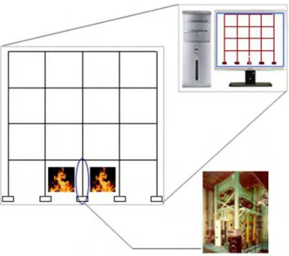
The new test techniques is a combination of a simple analytical approach for determining the restraint effects from the structural system and a load controlled testing process through which the load is determined according to the calculated resistant condition of the structural system. Fig. 1 illustrates a more general process of the new hybrid test technique for
performance-based test of a column using the column furnace facility at the National research Center Canada. Using the new approach, the restraint condition of the structure is determined by modeling the entire structure using a structural analysis program or a simple calculation process, as described later in this report. The column will then be tested in fir, furnace, under variable axial load. The value of the axial load is determined according to the frame stiffness calculated by the analysis. This process can be implemented in real-time to feed back the test results into the analysis with the new mechanical properties of the column obtained from the test. For the sake of simplicity and application in practice, at this stage this study explores an approach through which the resistant condition, support stiffness, will be determined first by the analysis and considers constant restraint curve for the duration of the test.
Fig. 1. A hybrid testing technique for assessment of fire resistance of columns considering the restraint conditions from the structural system.
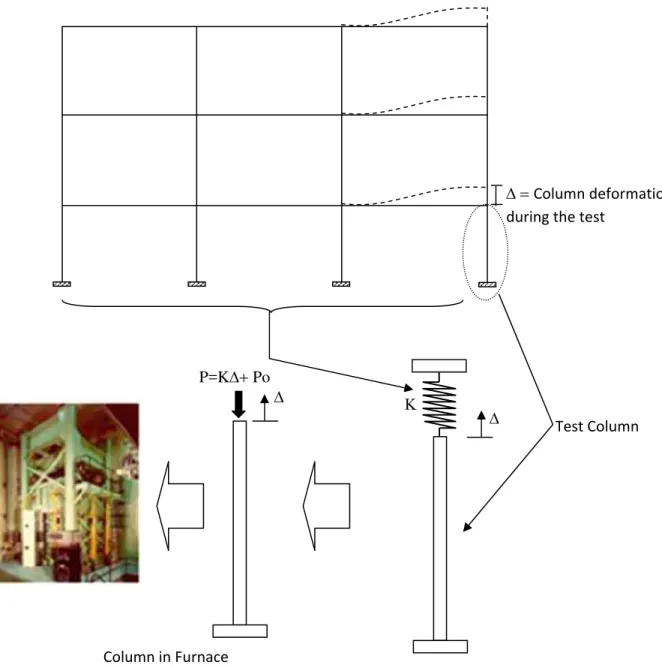
Fig. 2 illustrates the simple approach of the hybrid test technique for test of the right corner column in the first floor of a 3-bay 3-story frame, the test column. The main contribution from the frame in this method is the vertical stiffness in the direction of axial thermal expansion of columns. When the test column is exposed to fire, it elongates vertically due to thermal expansion which results in vertical displacement of the column by ∆ as shown in Fig. 2.
Δ = Column deformation during the test Δ Κ Δ P=KΔ+ Po Test Column Column in Furnace
Fig. 2. A simple performance-based test technique for fire resistance of columns considering the restraint conditions from the structural system.
When the column is without any restraint, or free from the frame, as currently considered for columns fire resistance test, only the initial axial load Po is applied on the column. In the new approach, in order to include the effect of frame restraint, an additional deformation-dependent load, (kΔ), is added to the initial load determined by Eq. (1), as shown in Fig. 2:
P=KΔ+ Po (1) where, ∆ is the column axial deformation during the test, K is the vertical stiffness of the frame at the connection point with the column, and Po is the initial applied axial load. The test can be implemented either load or displacement controlled by employing the same equation, Eq. (1). The main challenge in this method is the calculation of the frame’s vertical stiffness K. There are two methods to calculate K; using a structural analysis program or a simplified approach, both methods are described in this report. Studies are currently carried out at the National Research Council Canada to simulate lateral floor thermal expansion induced on the columns during fire and to include this component in the fire resistance test.
3. MODELING STRUCTURAL SYSTEM STIFFNESS
There are two approaches to determine vertical stiffness K of the structural system: Full Structural Analysis method and the Simplified Method; explained in this section.
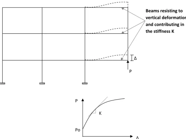
P Δ Beams resisting to vertical deformation Δ and contributing in the stiffness K Δ P K Po
Fig. 3. Process of determining vertical stiffness of the structural system K by the Full-Analysis method.
3.1. Full Structural Analysis Method
This is a comprehensive approach through which the entire frame is simulated and modeled using a structural analysis program. In this study, a computer program called SAFIR, developed at the University of Liege for the simulation of the behavior of building structures subjected to fire, is implemented. Using this approach, the entire frame is modeled when only the test column, for instance, first-floor right corner column, is exposed to fire. The analysis is implemented and the load P-deformation Δ curve is obtained. The slop of the P-Δ curve is derived at the vertical stiffness of the structural system K. Fig. 3 shows the frame in Fig. 2 with components of load and deformation interacted between the test column and the frame.
Although the P-Δ curve is nonlinear, in most cases column load P, in Fig.2, would not exceed the linear part of the P-Δ curve and may be considered constant for duration of the test. This
provides more stability and makes the load control process of the test easier.
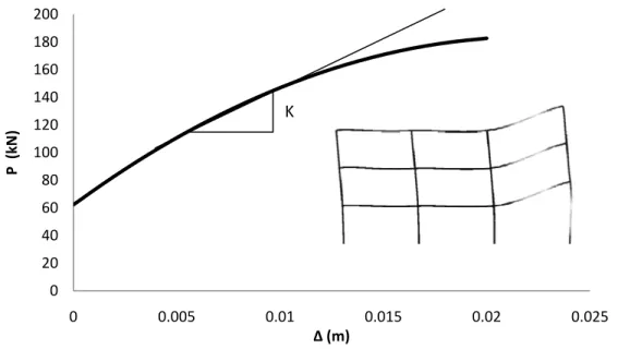
The full analysis method was applied using the SAFIR program for a three story frame, Frame No. 7, illustrated in Fig 10, with material properties provided in Table 1. The results were illustrated in Fig. 4. As described earlier, the P-Δ curve was obtained by simulating the entire frame and exposing only the test column to the ASTM E119 fire. This is applicable for the case when the analysis program is capable of simulating the response of structures in fire. However, if such a program is not available, the designer may employ any structural analysis software used for ambient temperature by removing the test column, then applying vertical deformation ∆ at the disconnected point and measuring the load reaction P to determine K, as illustrated in Fig.3.
0 20 40 60 80 100 120 140 160 180 200 0 0.005 0.01 0.015 0.02 0.025 P (kN) Δ (m) K
An attempt was made to develop a simple analytical process to determine the structure vertical stiffness K implemented in hand calculation. In this method, K is determined according to Eq. (2), derived for a beam with flexible supports.
∑ .
(2)
where, n is number of beams that are resisting against vertical movement of the test column (in Fig. 4 three beams are resisting to vertical movement, and accordingly deformed, therefore, n=3 which is for a corner test column but in case of the middle test columns in the same figure, n=6),
E, I and L are Modulus of Elasticity, Moment of Inertia and Length of the beam i respectively,
and α, the beam connections rigidity factors, is between (0 to 1), which is determined based on the rigidity ratio of the beams’ connections as described in the next section.
3.2.1 Beam connections rigidity factor
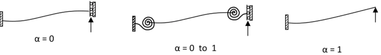
The rigidity of the beams’ connections is included in Eq. (2) using factor α. Fig. 5 illustrates values of α for different beam’s support conditions.
Fig. 5. Factor α for fixed, variable and cantilever beams. In general, factor α could be determined by Eq. (3).
(3) where, again , E, I and L are components of the beam i and Kj and Kk are support rigidity to
rotation determined by Eq. (4)
∑ ∑ (4)
where, E, I and L are determined for the beams and columns connected to beam i , except beam i, at the beam end j and k, mj and mk are total number of beams and columns connected to the beam
end j and k respectively, and , lateral rigidity factor of the beams and columns in Eq. (4), is between (1 to 4) determined based on the beam’s or column’s rigidity against lateral movement.
α = 1 0
α =
3.2.2 Lateral rigidity factor
For all beams, lateral rigidity factor can be determined based on the axial rigidity of the columns in the frame, which is comparatively high. In low- to moderate-rise frame, for simplicity a value between would be reasonable. This applies also to columns in a braced frame, where lateral movements are limited by the bracing system. In this study, for these two groups, a value of is considered. However, for columns in moment-resisting frames is relatively more variable and determined according to Eq. (5).
. .
∑ ∑
(5) where, E, I and L are calculated for the column and:
(6) where, E, I and L are components of the column j in floor i, n and m are number of floors and number of columns in each floor, for the part of frame in and underneath the column in question, respectively.
For simplicity one may consider all the columns to be similar in Eq. (5) and (6) resulting in: (7) For test column in Fig. 2, n=1 and m= 4, therefore, = 3.4
Test Column
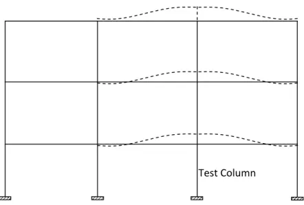
Fig. 6. Roughly symmetric deformation and rotation in connections in frames when a middle column is selected for the test.
Eq. (6) applies when all connections are rigid for rotation. In case of a middle test column, due to more likelihood of symmetric frame deformations, as the results of the test column vertical displacement (shown in Fig. 6), this equation may be applicable. However, for a corner test column, due to asymmetric deformations (see Fig. 4), connections are rotating according to the beams stiffness. Based on the analysis implemented for different frames in this study, when a
Eq. (5). This value may be reduced for frames with higher number floor. However, for the group of the frames in this study such a value seems reasonable.
4. APPLICATION AND EXAMPLES
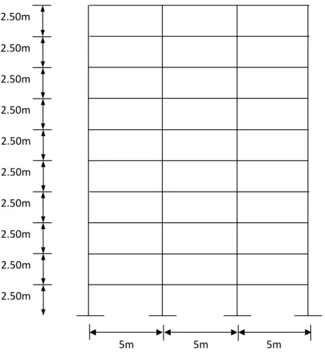
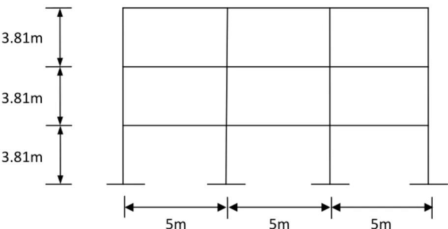
Four reinforced concrete frame prototypes with different heights have been selected for this study. The analysis is implemented for both corner and middle test column cases. Further details on the prototypes are provided in Table 1. Dimensions of the frames and further details on the cross-sections of beams and columns are provided in Figs. 7 to 12.
Table 1. Details of the reinforced concrete frame prototypes.
Frame No.
No. of Stories
Test Column Column Cross Section (mm) Column Length (mm) Beam Cross Section (mm) Beam Length (mm) Concrete Strength (MPa) 1 10 1st floor, corner 500 x 500 2500 500 x 300 5000 24 2 10 1st floor, middle 500 x 500 2500 500 x 300 5000 24 3 6 1st floor, corner 500 x 500 2500 500 x 300 5000 24 4 6 1st floor, middle 500 x 500 2500 500 x 300 5000 24 5 3 1st floor, corner 500 x 500 2500 500 x 300 5000 24 6 3 1st floor, middle 500 x 500 2500 500 x 300 5000 24 7 3 1st floor, corner 305 x 305 3810 500 x 300 5000 36.9 8 3 1st floor, middle 305 x 305 3810 500 x 300 5000 36.9
4.1 Results of analysis and model verification
Both the full analysis method, using the SAFI program, and the simplified method were
implemented to determine the vertical frame stiffness corresponding to test column of the frame prototypes. The results were illustrated and compared in Figs. 14 to 21. The comparison and correlation between the results of the two approaches indicate that the simplified method provides relatively acceptable values for the frame equivalent vertical stiffness K of the frames. The simplified method can be implemented in hand calculation and more applicable in practice compared to the full analysis. In the next section, the detailed analytical process by the simplified method for one of the frame prototype is provided.
Fig. 7. Dimensions of the reinforced concrete frame prototypes No. 1 and 2.
Fig. 8. Dimensions of the reinforced concrete frame prototypes No. 3 and 4.
5m 5m 5m 2.50m 2.50m 2.50m 2.50m 2.50m 2.50m 2.50m 2.50m 2.50m 2.50m 5m 5m 5m 2.50m 2.50m 2.50m 2.50m 2.50m 2.50m
Fig. 9. Dimensions of the reinforced concrete frame prototypes No. 5 and 6.
Fig. 10. Dimensions of the reinforced concrete frame prototypes No. 7 and 8.
Fig. 11. Details of the cross-section for columns.
5m 5m 5m 3.81m 3.81m 3.81m b) Prototype No. 7 & 8 a) Prototype No. 1 ‐6 305 mm 500 mm 500 mm Hoops D10@10 Main Bars: 4(25M) fy = 350 MPa 305 mm Hoops 10M@305 Main Bars: 4(25M) fy = 443.7 MPa 5m 5m 5m 2.50m 2.50m 2.50m
300 mm 500 mm Main Bars: 4(D19) fy = 380 MPa Hoops D10@200
Fig. 12. Details of the cross-section for beams.
4.2 An example with calculation details
This example describes the calculation process for the frame prototype No. 5, shown in Fig. 9, a 3 story reinforced concrete frame, where the right corner column on the first floor is selected as the test column, similar to the frame and test column in Fig.2.
Step 1 Determine section properties
. . E+10 . . . E‐3 . . . E‐3
Step 2 Determine lateral rigidity factors for beams and columns
For all beams lateral rigidity factor is considered =3.5. For columns, since the frame is a moment-resisting frame, lateral rigidity must be determined using Eq. (5) or Eq. (7). Hence: a) For columns on first floor:
. E . E
. .
.
. . . E . E
. .
.
The same result is obtained using Eq. (7). Note that the test column is a corner column and the value from Eq. (5) or (7) must be multiplied by 0.55, as described earlier.
= . .
.
b) For columns on second floor: Similar to (a):
.
.
c) For columns on third floor:
. j1 J2 J3 k1 k2 k3 5m 5m 5m 2.50m 2.50m 2.50m
Fig. 13. Details of the cross-section for beams.
Step 3 Determine beam connections stiffness
a) For connection j1 of the beam (j1,k1) on the first floor: zero beam and two columns are
connected to j1 (the main beam (j1,k1) should not be counted).
. . E . . E . E
b) For connection k1 of the beam (j1,k1) on the first floor: one beam and two columns are
connected to k1 (again the main beam (j1,k1) is not counted).
. . E . . E . . E . E . E
c) For connection j2 of the beam (j2,k2) on the 2nd floor: zero beam and two columns are
connected to j2 (the main beam (j2,k2) is not counted).
. . E . . E . E
d) For connection k2 of the beam (j2,k2) on the 2nd floor: one beam and two columns are
connected to k2 (again the main beam (j2,k2) is not counted).
. . E . . E . . E . E . E
e) For connection j3 of the beam (j3,k3) on the 3rd floor: zero beam and one column are connected
to j3 (the main beam (j3,k3) is not counted).
. . E . . E . E
f) For connection k3 of the beam (j3,k3) on the 3rd floor: one beam and one column are connected
to k3 (again the main beam (j3,k3) is not counted).
. . E . . E . . E . E . E
Step 4 Determine beam connections factors
a) First Floor . E . E . E . E . E. E . b) Second Floor . E . E . E . E . E. E =0.275
c) Third Floor . E . E . E . E . .E E . .
Step 5 Determine vertical stiffness for each floor
a) First Floor . . . . E . E . . b) Second Floor . . . . E . E . . c) Third Floor . . . . E . E . . . . . . ∆ ∆∆ ∆
Step 6 Determine total vertical stiffness
Note:
The above vertical stiffness is for non-cracked section. In case of reinforced concrete frame, after cracking of beam section, vertical stiffness K must be determined considering the cracked cross section. This will require using Icr or moment of inertia of the cracked section. In this study, for
simplicity Icr, is calculated using a simple flexure section analysis giving Icr=0.3Ibeam. The above
process is implemented considering 0.3 Ibeam, which resulted in:
Therefore total vertical stiffness will vary according to the deformation Δ from K (with no crack) to Kcr.
For the beams in this study Δcr=0.027m
As results we have . The P-Δ curve for this frame is plotted in Fig. 18 along with the results from the full analysis method. This calculation process can be simply implemented using an EXCEL worksheet.
∆
5. CONCLUSIONS
A simple calculation process was developed for the performance-based fire resistance
assessment of the column considering the restraint condition due to axial interaction between the column and the frame system. The approach can be implemented in hand calculation and the results of the method are comparable with those obtained by a full structural analysis using a computer program. For application in practice, the model needs to be verified through a future experimental program. Studies are still carried out to implement the approach for a wider range of frame types, as well as, consideration of the lateral load, due to floor thermal expansion, in the test technique.
6. REFERENCES
Gillie M., Usmani A., Rotter J. M., A structural analysis of the first Cardington test, Journal of Constructional Steel Research, 57 (6), 581-601, 2001.
Lie, T.T., and Woollerton, J.L. (1988). “Fire resistance of reinforced concrete columns – Test results.” National Research Council Canada, Internal Report No. 569.
Usmani A. S., Rotter J. M., Lamont S., Sanad A.M., Gillie M., Fundamental principles of structural behaviour under thermal effects, Fire Safety J, 36(8): 721-744, 2001. [10] Usmani A., A Very Simple Method for Assessing Tall Building Safety in Major Fires, Proceedings of the Fifth International Conference on Structures in Fire, May 2008.
Frame No. 1 0 100 200 300 400 500 600 0 0.005 0.01 0.015 Deformation (m) Lo a d (k N ) Full Analysis Simplified Method Fig. 14. Load-Deformation (P-Δ) curve for prototype No. 1.
Frame No. 2 0 200 400 600 800 1000 1200 0 0.002 0.004 0.006 0.008 Deformation (m) Lo ad (k N ) Full Analysis Simplified Method Fig. 15. Load-Deformation (P-Δ) curve for prototype No. 2.
Frame No. 3 0 100 200 300 400 0 0.005 0.01 0.015 0.02 Deformation (m) Lo ad (k N ) Full Analysis Simplified Method Fig. 16. Load-Deformation (P-Δ) curve for prototype No. 3.
Frame No. 4 0 100 200 300 400 500 600 700 800 0 0.005 0.01 0.015 Deformation (m) Fo rc e (k N ) Full Analysis Simplified Method Fig. 17. Load-Deformation (P-Δ) curve for prototype No. 4.
Frame No. 5 0 50 100 150 200 0 0.005 0.01 0.015 0.02 0.025 Deformation (m) Lo ad (k N ) Full Analysis Simplified Method Fig. 18. Load-Deformation (P-Δ) curve for prototype No. 5.
. Frame No. 6 0 100 200 300 400 500 0 0.005 0.01 0.015 0.02 0.025 Deformation (m) Lo a d (k N ) Full Analysis Simplified Method
Fig. 19. Load-Deformation (P-Δ) curve for prototype No. 6.
Frame No. 7 0 50 100 150 200 250 0 0.005 0.01 0.015 0.02 0.025 0.03 Deformation (m) Lo ad (k N ) Full Analysis Simplified Method Fig. 20. Load-Deformation (P-Δ) curve for prototype No. 7.
Frame No. 8 0 100 200 300 400 500 600 0 0.005 0.01 0.015 0.02 Deformation (m) Lo ad (k N ) Full Analysis Simplified Method . Fig. 21. Load-Deformation (P-Δ) curve for prototype No. 8.