Publisher’s version / Version de l'éditeur:
Creep, Shrinkage and Durability Mechanics of Concrete and Concrete Structures, Two Volume Set : Proceedings of the CONCREEP 8 conference held in Ise-Shima, Japan, 30 September - 2 October 2, pp. 1441-1447, 2008-09-30
READ THESE TERMS AND CONDITIONS CAREFULLY BEFORE USING THIS WEBSITE. https://nrc-publications.canada.ca/eng/copyright
Vous avez des questions? Nous pouvons vous aider. Pour communiquer directement avec un auteur, consultez la
première page de la revue dans laquelle son article a été publié afin de trouver ses coordonnées. Si vous n’arrivez pas à les repérer, communiquez avec nous à PublicationsArchive-ArchivesPublications@nrc-cnrc.gc.ca.
Questions? Contact the NRC Publications Archive team at
PublicationsArchive-ArchivesPublications@nrc-cnrc.gc.ca. If you wish to email the authors directly, please see the first page of the publication for their contact information.
NRC Publications Archive
Archives des publications du CNRC
This publication could be one of several versions: author’s original, accepted manuscript or the publisher’s version. / La version de cette publication peut être l’une des suivantes : la version prépublication de l’auteur, la version acceptée du manuscrit ou la version de l’éditeur.
Access and use of this website and the material on it are subject to the Terms and Conditions set forth at Extending service life of high performance concrete bridge decks with internal curing
Daigle, L.; Cusson, D.; Lounis, Z.
https://publications-cnrc.canada.ca/fra/droits
L’accès à ce site Web et l’utilisation de son contenu sont assujettis aux conditions présentées dans le site LISEZ CES CONDITIONS ATTENTIVEMENT AVANT D’UTILISER CE SITE WEB.
NRC Publications Record / Notice d'Archives des publications de CNRC:
https://nrc-publications.canada.ca/eng/view/object/?id=7899de5e-d302-4d38-aee8-b130b5d14bde https://publications-cnrc.canada.ca/fra/voir/objet/?id=7899de5e-d302-4d38-aee8-b130b5d14bde
http://irc.nrc-cnrc.gc.ca
E x t e n d i n g s e r v i c e l i f e o f h i g h p e r f o r m a n c e
c o n c r e t e b r i d g e d e c k s w i t h i n t e r n a l c u r i n g
N R C C - 5 0 4 2 9
D a i g l e , L . ; C u s s o n , D . ; L o u n i s , Z .2 0 0 8 - 0 9 - 3 0
A version of this document is published in / Une version de ce document se trouve dans:
8th International Conference on Creep, Shrinkage and Durability of Concrete and Concrete Structures (CONCREEP 8), ISE-Shima, Japan, Sept. 30 – Oct. 2, 2008
The material in this document is covered by the provisions of the Copyright Act, by Canadian laws, policies, regulations and international agreements. Such provisions serve to identify the information source and, in specific instances, to prohibit reproduction of materials without written permission. For more information visit http://laws.justice.gc.ca/en/showtdm/cs/C-42
Les renseignements dans ce document sont protégés par la Loi sur le droit d'auteur, par les lois, les politiques et les règlements du Canada et des accords internationaux. Ces dispositions permettent d'identifier la source de l'information et, dans certains cas, d'interdire la copie de documents sans permission écrite. Pour obtenir de plus amples renseignements : http://lois.justice.gc.ca/fr/showtdm/cs/C-42
8th Intl. Conf. on Creep, Shrinkage and Durability of Concrete and Concrete Structures, Ise-Shima, Japan, Sept. 30 – Oct. 2, 2008
Extending service life of high performance concrete bridge decks
with internal curing
L. Daigle, D. Cusson & Z. Lounis
National Research Council Canada, Ottawa, Ontario, Canada
ABSTRACT: High performance concrete (HPC) bridge decks are prone to premature cracking if movement is restrained. Internal curing (IC) can reduce shrinkage cracking in concrete structures, thus improving their per-formance and service life. However, there is very limited information available in the literature on the possi-ble extension of service life due to internal curing. This paper addresses this question by using predictive models to estimate the service lives of typical bridge decks made with concrete using internal curing as op-posed to conventional curing. Four options are compared: (i) normal concrete deck; (ii) HPC deck; (iii) HPC deck with internal curing; and (iv) very high performance concrete deck with internal curing. It was found that the use of internal curing can increase the service life of HPC bridge decks by almost ten years, which is mainly due to due a slower penetration of chlorides as a result of reduced cracking.
1 INTRODUCTION
Proper curing of concrete structures is important to ensure that they meet their intended performance and durability requirements. In low permeability concrete, conventional external curing may not be effective in preventing self-desiccation at the centre of thick concrete elements. Internal curing (IC) is a technique that can be used to provide additional moisture in concrete for a more effective cement hy-dration and reduced self-desiccation (Rilem TC-196, 2007). For that purpose, saturated porous light-weight aggregate (LWA) can be mixed into concrete in order to supply an internal source of water, which can replace the mix water consumed by chemical shrinkage during cement hydration (Weber & Reinhardt 1997). The required mass of LWA to in-troduce in concrete for adequate internal curing can be determined following the simple design proce-dure suggested by Bentz et al. (2005).
Internal curing with LWA has been successfully used recently in large construction projects of nor-mal-density concrete structures. For example, in January 2005, about 190 000 m3 of internally cured concrete was used in a large paving project in Hut-chins, Texas (Villarreal & Crocker 2007). Field ob-servations reported marginal pavement cracking, and strength tests indicated that 7-day flexural strengths reached 90% to 100% of the required 28-day flex-ural strength due to an improved cement hydration. They also found that the compressive strengths of
air-cured cylinders were similar to those of wet-cured cylinders at all ages, suggesting that concrete with internal curing is less sensitive to poor external curing practices or unfavorable ambient conditions.
Although the benefits of internal curing for high performance concrete structures have been evi-denced in laboratory and field investigations (such as those previously mentioned), the literature offers no significant quantitative information on the extent of service life that internal curing can offer to con-crete structures. Using available test data from the literature, along with predictive models and conser-vative engineering judgment, the objective of this paper is to provide estimates of service lives for concrete bridge decks made with concrete using ei-ther conventional curing or internal curing.
2 CASE STUDY
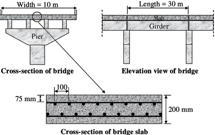
To demonstrate the benefits of internal curing for high performance concrete structures in terms of service life performance, a typical concrete bridge deck case study is used for the analysis. The bridge element under consideration is a 200-mm thick con-crete slab reinforced with conventional steel with a concrete cover of 75 mm, as shown in Figure 1. For simplicity, the concrete slab surface area is set to a width of 10 m and length of 30 m, supported by sin-gle-span concrete girders separated by expansion joints. The bridge superstructure and substructure are not considered in the analysis.
-Cross-section of bridge Elevation view of bridge
Cross-section of bridge slab
Width = 10 m 200 mm 75 mm 100 Pier Length = 30 m Girder Slab
Cross-section of bridge Elevation view of bridge
Cross-section of bridge slab
Width = 10 m 200 mm 75 mm 100 Pier Length = 30 m Girder Slab
Figure 1. Geometry of case study bridge deck.
Table 1 presents the four concrete bridge deck options compared in this case study, including: (i) a bridge deck made of good quality normal concrete (NC) with a water-to-cementitious materials ratio (w/cm) of 0.4, and no supplementary cementing ma-terials (SCM); (ii) deck made of high performance concrete (HPC), assuming early-age cracking due to autogenous shrinkage, with a w/cm of 0.35 and 25% SCM as partial cement replacement by mass; (iii) deck made of high performance concrete with inter-nal curing (HPC-IC), also with a w/cm of 0.35 and 25% SCM; and (iv) deck made of very high per-formance concrete with internal curing (VHPC-IC), with a lower w/cm of 0.30, and 25% SCM. In this case, the SCM consist of 5% silica fume and 20% slag, and the LWA is assumed to provide 28 kg/m3 of internal curing water in the concrete.
T
able 1. Design of selected concrete bridge deck options. Deck option Initial
cracking Water (kg/m3) Cement (kg/m3) SCM (%) LWA (kg/m3) NC No 140 350 0 0 HPC Yes 160 450 25 0 HPC-IC No 160 450 25 185 VHPC-IC No 160 525 25 185
Note: SCM included in cement content.
The concrete bridge decks are directly exposed to de-icing salts in winter over their respective service lives. For the four deck options, a surface chloride concentration of 9 kg/m3 is assumed, which is typi-cal of the severe conditions found in Northern USA or Canada (Weyers 1998). A chloride threshold of 0.7 kg/m3 is assumed for the conventional steel rein-forcement (ACI Committee 222, 2001), over which corrosion can initiate; and a moderate corrosion rate of 0.5 μA/cm2
is assumed once corrosion has started (Rodriguez et al. 1994). It can be argued that these values may differ from actual values depending on the severity and variability of the local exposure conditions; however, the findings of this case study should be considered with respect to the normal concrete deck (base case), since all deck options are compared using the same surface chloride concentration, chloride threshold and corrosion rate.
3 SERVICE LIFE PERFORMANCE
In this study, most of the service life performance analysis was conducted using the analytical models developed by Lounis et al. (2006) and implemented in NRC’s SLAB-D software (Daigle and Lounis 2006). The effects of early-age cracking and internal curing on chloride penetration were not included in the original SLAB-D models, but estimated using additional models presented in this paper.
Figure 2 presents the different stages of corro-sion-induced damage developing in a typical rein-forced concrete bridge deck. With time, each stage is the result of a higher damage level first caused by the initial cracking and then by the corrosion proc-ess. The different stages include: (i) early-age crack-ing due to restrained shrinkage (if any); (ii) initiation of reinforcement corrosion after a relatively long pe-riod of chloride diffusion through concrete; (iii) in-ternal cracking around the reinforcing bars due to a build-up of corrosion products; (iv) surface cracking due to further progression of corrosion-induced cracks; (v) delamination or spalling of the concrete cover depending on the reinforcement spacing and diameter, and concrete cover thickness; and finally (vi) failure of the concrete deck, depending on the amount of delamination or spalling that is tolerated by the bridge owner before deck rehabilitation or re-placement is considered. Time Da ma ge l eve l Initial cracking Rebar corrosion Internal cracking Surface cracking Delamination or spalling Failure Service life
Corrosion initiation Propagation
Cl-Cl- Cl- Cl -Cl
-Shrinkage cracking Cl
-diffusion “Rust” and
stress build-up Surface damage Time Da ma ge l eve l Initial cracking Rebar corrosion Internal cracking Surface cracking Delamination or spalling Failure Service life
Corrosion initiation Propagation
Cl-Cl- Cl- Cl -Cl
-Shrinkage cracking Cl
-diffusion “Rust” and
stress build-up Surface damage Figure 2. Concept used for service life performance analysis.
3.1 Initial cracking due to restrained shrinkage Early-age cracking is a common problem on con-crete bridge decks (TRB 1996) as more than 100,000 bridges in the United States are reported to have de-veloped transverse cracking shortly after construc-tion. This type of through cracking is of great con-cern to engineers and bridge owners since it may lead to premature reinforcement corrosion and con-crete deterioration due to accelerated moisture and salt ingress through the cracks.
Rodriguez & Hooton (2003) studied the influence on chloride penetration of artificially created parallel cracks with widths ranging from 0.08 mm to 0.68 mm. They concluded that chloride diffusion in con-crete was not affected by the width and wall rough-ness of individual cracks for the ranges studied. This finding allows the use of a simplified smeared ap-proach proposed by Boulfiza et al. (2003) to esti-mate the effect of cracks on chloride ingress. It as-sumes that the chloride ingress into cracked concrete can be approximated using Fick’s second law of dif-fusion, in which the following apparent diffusion coefficient (Dapp) is used:
cr cr cr c app D s w D D = + (1)
where Dc is the chloride diffusion coefficient in
un-cracked concrete; wcr is the crack width; scr is the
crack spacing; and Dcr is the diffusion coefficient
in-side the crack, which is assumed to be 5x10⁻¹⁰ m2/s (Boulfiza et al. 2003). In the present case study, the value of wcr/scr is set to 0.0003, which corresponds
to the 7-day value of autogenous shrinkage strain measured for a concrete that was very similar to that selected for the HPC deck option (Cusson & Hoogeveen 2008). As a result, an average increase in the chloride diffusion coefficient of approxi-mately 1.5x10⁻¹³ m2/s is expected. For the decks made with NC, HPC-IC and VHPC-IC, the effect of cracking on chloride ingress is neglected (i.e. Dapp = Dc), assuming that autogenous shrinkage in these
concretes is not significant enough to result in con-crete cracking.
3.2 Corrosion initiation due to chlorides
In uncracked concrete, the chloride ingress was de-termined by using Crank’s solution of Fick’s second law of diffusion (Crank 1975, Tuutti 1982):
⎥ ⎥ ⎦ ⎤ ⎢ ⎢ ⎣ ⎡ ⎟ ⎟ ⎠ ⎞ ⎜ ⎜ ⎝ ⎛ − = t D x erf C t x C S 2 1 ) , ( (2)
where C(x,t) is the chloride concentration at depth x after time of exposure t; Cs is the chloride
concentra-tion at the concrete surface; and erf is the error func-tion. Equation 2 can also be rearranged to predict the time of corrosion initiation (ti) by setting C(x,t)
equal to a chloride threshold value (Cth), at which
the corrosion of the reinforcing steel is expected to initiate, and x equal to the effective cover depth of the reinforcing steel (dc).
The chloride diffusion coefficients of the differ-ent concretes were estimated based on their water-cement ratios and the types of SCM selected for this case study. The empirical models of Boulfiza et al. (2003) developed from a large set of literature data were used: 0 . 14 ) / ( 2 . 7 ) / ( 9 . 3 2+ − − = w cm w cm D Log C
(for concrete with no SCM) (3a)
7 . 13 ) / ( 4 . 5 ) / ( 0 . 3 2+ − − = w cm w cm D Log C
(for concrete with silica fume and slag) (3b) where Dc is expressed in units of m2/s. Table 2
pre-sents the resulting coefficients of diffusion calcu-lated for the different concretes considered, includ-ing the effect of initial crackinclud-ing on the apparent chloride diffusion coefficient (Dapp).
T
able 2. w/cm and diffusion coefficients.
Deck option w/cm Dc Dapp (10-13 m2/s) NC 0.40 18 18 HPC 0.35 6.6 8.1 HPC-IC 0.35 6.6 6.6 VHPC-IC 0.30 4.4 4.4
It is important to note that the estimated values of
Dc for the HPC-IC and VHPC-IC concretes are
con-sidered to be conservative values, since internal cur-ing can also enhance cement hydration, thus reduc-ing concrete permeability and diffusivity. Indirect observations of reduced permeability/porosity due to internal curing through improved early-age strengths can be found in the literature (Bentz 2007). Since there is not enough experimental data available in the literature to model the effect of internal curing on chloride diffusivity of concrete, this beneficial ef-fect of internal curing was not accounted for.
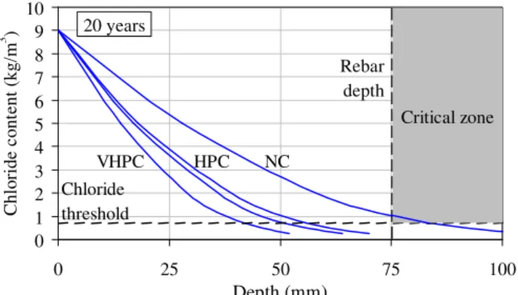
Figure 3 presents the chloride profiles calculated for the four different concrete bridge decks after a 20-year exposure to de-icing salts. The critical zone corresponds to chloride concentrations at the rein-forcement level (or deeper) that are higher than the chloride threshold of 0.7 kg/m3, over which initia-tion of steel corrosion is likely to occur. It can be seen that after 20 years only, the chloride concentra-tion in the normal concrete deck has reached the critical concentration at the 75-mm depth.
0 1 2 3 4 5 6 7 8 9 10 0 25 50 75 Depth (mm) Ch lor ide c ont e n t (k g/ m 3 ) Reba 100 r depth Chloride threshold NC HPC VHPC Critical zone 20 years
Figure 3. Chloride profiles in concrete after 20 years.
Figure 4 shows the chloride concentrations in the four concrete decks increasing over time at the rein-forcement level (75 mm). It is found that the
-ride concentrations would reach the threshold value after 16 years for the NC deck, 35 years for the HPC deck, 43 years for the HPC-IC deck, and 65 years for the VHPC-IC deck. The additional eight years provided by the use of internal curing can be attrib-uted to reduced cracking (lower Dapp).
0.0 0.5 1.0 1.5 2.0 2.5 3.0 3.5 4.0 0 10 20 30 40 50 60 7 Time (years) C hl or ide c ont e nt (kg/ m 3 ) Chloride threshold 0 NC HPC VHPC-IC 75 mm HPC-IC
Figure 4. Chloride ingress over time at reinforcement level.
3.3 Corrosion-induced damage
Assuming that concrete is a homogeneous elastic material (in tension), with a tensile strength (f’t), and
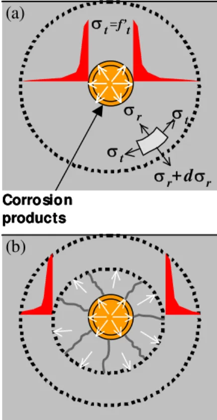
that corrosion products are equally distributed around the perimeter of the reinforcing bars (Bažant 1979), stresses generated in the concrete deck by corrosion built-up products can be estimated using the thick-wall cylinder model (Timoshenko 1956). This model allows the calculation of the increase in the rebar diameter (Δd) related to different stages of
corrosion-induced damage (Figure 5).
Corrosion products σr+ dσr σr σ t σt σt=f’t (a) (b) Corrosion products σr+ dσr σr σ t σt σt=f’t (a) Corrosion products σr+ dσr σr σ t σt σt=f’t (a) (b) (b)
Figure 5. Thick-wall cylinder model of corroding reinforced concrete deck: (a) Tensile stresses developed at crack initia-tion; (b) Propagation of internal cracks in thick-wall concrete cylinder. Adapted from Lounis et al. 2006.
The corrosion propagation times (tp),
correspond-ing to the onset of internal crackcorrespond-ing, surface crack-ing, and delamination/spalling are found as follows:
⎥ ⎦ ⎤ ⎢ ⎣ ⎡ − Δ = s r r p j S d d t ρ α ρ π 1 2 ) ( (4)
where d is the rebar diameter; S is the rebar spacing;
jr is the rust production per unit area (Bažant 1979); ρr is the density of corrosion products (assumed at
3600 kg/m3 for Fe(OH)3); ρs is the density of steel
(7860 kg/m3); and α is the molecular weight ratio of metal iron to the corrosion product (assumed at 0.52). The total time to reach a given corrosion-induced damage level is the sum of the corrosion ini-tiation time (ti) and the individual corrosion
propa-gation times (tp) up to that level.
Work by Allan & Cherry (1992) showed that there may be a porous zone around the steel rein-forcement at the steel/concrete interface, in which a specific quantity of corrosion products can accumu-late before tensile stresses can actually develop in concrete, thus delaying the damage initiation of the concrete cover. The thickness of the porous zone may be in the order of 12.5 μm (Liu & Weyers 1998); however, the thickness and porosity of the porous zone depend on many factors, such as: w/cm, presence and type of SCM and hydration, which in turn influence the overall concrete porosity.
Internal curing may affect the porous zone in two competing ways: (i) by decreasing the porosity of the cement paste due to an improved cement hydra-tion; and (ii) by increasing the porosity of the zone due to the relatively large and empty pores left in the LWA after the internal curing water has migrated into the cement paste. Due to the lack of data in the literature on the effect of internal curing and w/cm ratio on the thickness and porosity of the porous zone, this possible beneficial effect has been ne-glected in the analysis. Preliminary calculations in-dicate that neglecting the effect of the porous zone would provide more conservative estimates of ser-vice lives by at most 2 or 3 years only.
3.4 Estimated service life
In this case study, the service life of a bridge deck is defined as the time to initiate delamination or spalling (which ever comes first). Figure 6 illustrates the average service life estimated for each concrete deck option, in which the times to reach lower levels of concrete damage are also illustrated. Based on the above hypotheses, the service life increased due to the use of a lower water-cement ratio (reduced chlo-ride diffusion), in general, and the reduction of early-age cracking due to internal curing. The ser-vice lives were 19 years for the 0.40 w/cm NC deck; 38 years for the 0.35 w/cm HPC deck; 46 years for
the 0.35 w/cm HPC-IC deck; and 68 years for the 0.30 w/cm VHPC-IC deck. For simplicity, other fac-tors such as live loads, dead loads and thermal ef-fects were not considered in this analysis.
0 10 20 30 40 50 60 70 80 NC HPC HPC-IC VHPC-IC Ti me ( y ea rs ) Delamination Surface cracking Internal cracking Corrosion 19 years 38 years 46 years 68 years
Figure 6. Service life predictions from deterministic analysis. The service live predictions presented in Figure 6 were obtained through a deterministic analysis, i.e. an analysis that do not consider the variability and uncertainty associated with the main parameters governing the different mechanisms of deterioration of reinforced concrete decks. Deterministic analyses are based on mean or characteristic values of the variables and can only predict the times to reach the different stages of corrosion initiation and corrosion-induced damage caused by an “average” condition.
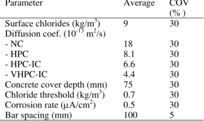
The variability and uncertainty of the main pa-rameters (e.g. material properties, structure dimen-sions, reinforcement, initial conditions, and envi-ronment) that govern service life predictions are the sources of the field-observed variable performance of concrete decks, which is better described with a reliability-based approach. The same four concrete deck options were analyzed with the reliability-based option of SLAB-D, considering the variability of six parameters (Table 3) expressed in terms of their coefficients of variation (COV).
Table 3. Average and COV values of main parameters.
Parameter Average COV
(% ) Surface chlorides (kg/m3) 9 30 Diffusion coef. (10-13 m2/s) - NC - HPC - HPC-IC - VHPC-IC 18 8.1 6.6 4.4 30 30 30 30
Concrete cover depth (mm) 75 30
Chloride threshold (kg/m3) 0.7 30
Corrosion rate (μA/cm2
) 0.5 30
Bar spacing (mm) 100 5
Figure 7 presents the results from the reliability analysis for the four deck options, in which the prob-ability of delamination increased over time. Consid-ering that the bridge deck can be divided into a very large number of small surface areas with the same probability (P%) of delamination after a number of years (t), it can be approximated that a certain
per-percentage (P%) of them are delaminated. The 10%, 25% and 50% probabilities of delamination are high-lighted in Figure 7 (short vertical lines) for the four options as they set the limits between the five condi-tion states for concrete deck condicondi-tion assessment (Table 4) defined in the AASHTO (1998) Guide, which is used in the bridge management system of many states in USA.
Table 4. AASHTO description of deck condition states. Condition
state
Description
1 The surface of the deck has no patched area and
no spalls in the deck surface.
2 The combined distress area (i.e. existing patches, delamination and spalling) of the deck is less than 10%.
3 The combined distress area of the deck is
be-tween 10% and 25%.
4 The combined distress area of the deck is
be-tween 25% and 50%.
5 The combined distress area of the deck is more
than 50%.
For the normal concrete deck, condition states 3, 4 and 5 are reached after approximately 8, 13, and 19 years. For the HPC, HPC-IC and VHPC-IC decks, these same condition states are reached after 15, 24 and 38 years; 18, 29 and 47 years; and 27, 44, and 70 years, respectively. As the apparent coeffi-cients of diffusion of the four investigated deck op-tions decreased, the times to reach condition state 3 (and subsequent states) increased. Depending on bridge owner policy and the estimated costs and benefits of repairs, the optimum recommended ac-tion to take for each deck condiac-tion state can be dif-ferent, ranging from the “do-nothing” approach, to delamination and spalling repairs, and ultimately to deck replacement. In addition to the extended ser-vice life provided by reduced initial cracking and re-duced chloride diffusion coefficients, the reliability-based analysis also shows that the use of lower w/c concretes with internal curing results in longer peri-ods of time before major repairs or rehabilitation be-come necessary, as indicated by the times needed to reach the condition states 3, 4 and 5.
0% 10% 20% 30% 40% 50% 60% 70% 80% 90% 100% 0 10 20 30 40 50 60 7 Time (years) P ro b ab ili ty o f d e la min a tio n 0 NC HPC HPC-IC VHPC-IC
Figure 7. Time-dependent probability of delamination.
-4 SUMMARY AND CONCLUSIONS
The service life performances of four bridge decks made with different concretes were estimated using predictive models for chloride diffusion, corrosion initiation, and corrosion propagation leading to cracking, delamination and/or spalling. The con-cretes selected for the bridge decks were: (i) normal concrete deck (w/cm=0.40); (ii) HPC deck (w/cm=0.35); (iii) HPC deck with internal curing (w/cm=0.35); and (iv) very high performance con-crete deck with internal curing (w/cm=0.30). From this study, the following conclusions can be drawn: 1. The use of internal curing can increase the
ser-vice lives of high performance concrete bridge decks by almost ten years, due to the absence of initial cracking.
2. This estimated life extension due to internal cur-ing alone is considered to be on the conservative side, since the beneficial effect of internal curing on the reduction of concrete permeability to wa-ter and chloride ions was not accounted for in this analysis.
3. The service life of concrete bridge decks can be extended by 50 years when considering the use of internally cured very high performance con-crete (w/cm=0.30) over normal concon-crete (w/cm=0.40).
4. The use of HPC and VHPC with internal curing in bridge decks can bring an additional economi-cal benefit by delaying the times at which repairs and rehabilitation of the reinforced concrete deck are required.
REFERENCES
AASHTO, “Guide for Commonly Recognized (CoRe) Struc-tural Elements”, American Association of State Highway and Transportation Officials, 1998 (Rev. 2002), 54 p. ACI Committee 222, Protection of Metals in Concrete Against
Corrosion, American Concrete Institute, Farmington Hills, 2001, 41 p.
Allan, M.L. & Cherry, B.W., “Factors controlling the amount of corrosion for cracking in reinforced concrete”, Journal of
Corrosion Engineering, 1992, p. 426-430.
Bažant, Z.P., “Physical model for steel corrosion in concrete sea structures – theory”. Journal of the Structural Division, Vol. 105(ST6), 1979, p. 1137-1153.
Bentz, D.P., “Internal curing of high-performance blended ce-ment mortars”, ACI Materials Journal, V. 104, No. 4, July-August 2007, p. 408-414.
Bentz, D.P., Lura, P. & Roberts, J.W., “Mixture proportioning for internal curing”, Concrete International, February 2005, p. 1-6.
Boulfiza, M., Sakai, K., Banthia, N. & Yoshida, H., “Predic-tion of chlrode ions ingress in uncracked and cracked con-crete”, ACI Materials Journal, Vol. 100, No. 1, January-February 2003, p. 38-48.
Crank, J., The mathematics of diffusion, 2nd edition, Oxford University Press, London, 1975, 414 p.
Cusson, D., Hoogeveen T., “Internal curing of high-performance concrete with pre-soaked fine lightweight ag-gregate for prevention of autogenous shrinkage cracking”,
Cement and Concrete Research, Vol. 38, No. 6, 2008, p.
757-765, doi:10.1016/j.cemconres.2008.02.001.
Daigle, L. & Lounis, Z., “SLAB-D Version 1.0 User’s Manual (and software) – Service Life Analysis of Bridge Decks”, National Research Council Canada, Institute for Research in Construction, 2006, 119 p.
Liu, Y. & Weyers, R.E., “Modeling the time-to-corrosion cracking in chloride contaminated reinforced concrete structures”, ACI Materials Journal, Vol. 95, No. 6, 1998, p. 675-681.
Lounis, Z., Martín-Pérez, B., Daigle, L. & Zhang, J., “Decision support tools for service life prediction and rehabilitation of concrete bridge decks”, NRC-IRC Final Client Report No.
B5318.2, April 2006, 256 p.
RILEM TC-196, “Internal curing of concrete”, State-of-the-art
Report of RILEM Technical Committee 196-ICC, Edited by
K. Kovler and O.M. Jensen, RILEM Publications S.A.R.L., Bagneux, France, 2007, 139 p.
Rodriguez, O.G. & Hooton, R.D., “Influence of cracks on chlo-ride ingress into concrete”, ACI Materials Journal, Vol. 100, No. 2, March 2003, p. 120-126.
Rodriguez, J., Ortega, L.M. & Garcia, A.M., “Assessment of structural elements with corroded reinforcement,”
Interna-tional Conference on Corrosion, Sheffield, U.K., July
1994, 16 p.
Timoshenko, S.P., Strength of Materials. Part II: Advanced
Theory and Problems, Princeton, NJ, 1956.
TRB, “Transverse cracking in newly constructed bridge decks”, National Co-operative Highway Research Program
Report 380, Transportation Research Board, National
Academy Press, Washington, 1996, 126 p.
Tuutti. K., “Corrosion of Steel in Concrete”, Ph.D. Thesis, Swedish Cement and Concrete Research Institute, Stock-holm, Sweden, 1982, 469 p.
Villarreal, V.H. & Crocker, D.A., “Better pavements through internal hydration”, Concrete International, February 2007, p. 32-36.
Weber, S. & Reinhardt, H.W., “A new generation of high per-formance concrete: concrete with autogenous curing”,
Ad-vanced Cement Based Materials, Vol. 6, No. 2, 1997, p.
59-68.
Weyers, R.E., “Service life model for concrete structure in chloride laden environments”, ACI materials journal, Vol. 95, No. 4, July-August 1998, p. 445-453.