Publisher’s version / Version de l'éditeur:
Vous avez des questions? Nous pouvons vous aider. Pour communiquer directement avec un auteur, consultez la
première page de la revue dans laquelle son article a été publié afin de trouver ses coordonnées. Si vous n’arrivez pas à les repérer, communiquez avec nous à PublicationsArchive-ArchivesPublications@nrc-cnrc.gc.ca.
Questions? Contact the NRC Publications Archive team at
PublicationsArchive-ArchivesPublications@nrc-cnrc.gc.ca. If you wish to email the authors directly, please see the first page of the publication for their contact information.
https://publications-cnrc.canada.ca/fra/droits
L’accès à ce site Web et l’utilisation de son contenu sont assujettis aux conditions présentées dans le site LISEZ CES CONDITIONS ATTENTIVEMENT AVANT D’UTILISER CE SITE WEB.
Interflam 2010, 12th International Conference on Fire Science & Engineering
Conference [Proceedings], pp. 1-12, 2010-07-05
READ THESE TERMS AND CONDITIONS CAREFULLY BEFORE USING THIS WEBSITE.
https://nrc-publications.canada.ca/eng/copyright
NRC Publications Archive Record / Notice des Archives des publications du CNRC : https://nrc-publications.canada.ca/eng/view/object/?id=f74c3459-d0dc-4349-a6d3-bdc1e80ae5f5 https://publications-cnrc.canada.ca/fra/voir/objet/?id=f74c3459-d0dc-4349-a6d3-bdc1e80ae5f5
NRC Publications Archive
Archives des publications du CNRC
This publication could be one of several versions: author’s original, accepted manuscript or the publisher’s version. / La version de cette publication peut être l’une des suivantes : la version prépublication de l’auteur, la version acceptée du manuscrit ou la version de l’éditeur.
Access and use of this website and the material on it are subject to the Terms and Conditions set forth at
Comparisons of furnace temperature and incident heat flux in wall and
floor furnaces controlled by six different temperature sensors
http://www.nrc-cnrc.gc.ca/irc
Com pa risons of furna c e t e m pe ra t ure a nd inc ide nt he a t flux in w a ll
a nd floor furna c e s c ont rolle d by six diffe re nt t e m pe ra t ure se nsors
N R C C - 5 2 6 4 4
S u l t a n , M . A .
J u l y 2 0 1 0
A version of this document is published in / Une version de ce document se trouve dans:
Interflam 2010, 12th International Conference on Fire Science & Engineering
Conference, Nottingham, UK, July 5-7, 2010, pp. 1-12
The material in this document is covered by the provisions of the Copyright Act, by Canadian laws, policies, regulations and international agreements. Such provisions serve to identify the information source and, in specific instances, to prohibit reproduction of materials without written permission. For more information visit http://laws.justice.gc.ca/en/showtdm/cs/C-42
Les renseignements dans ce document sont protégés par la Loi sur le droit d'auteur, par les lois, les politiques et les règlements du Canada et des accords internationaux. Ces dispositions permettent d'identifier la source de l'information et, dans certains cas, d'interdire la copie de documents sans permission écrite. Pour obtenir de plus amples renseignements : http://lois.justice.gc.ca/fr/showtdm/cs/C-42
COMPARISON OF FURNACE TEMPERATURE AND
INCIDENT HEAT FLUX IN WALL AND FLOOR
FURNACES CONTROLLED BY SIX DIFFERENT
TEMPERATURE SENSORS
Mohamed A. Sultan
Institute for Research in Construction National Research Council of Canada
Ottawa, Canada K1A 0R6
ABSTRACT
This paper presents and discusses the performance of six different types of temperature measuring sensors namely: the ASTM E119 shielded thermocouples, ISO 834 plate thermometers, directional flame thermometers, bare-bead thermocouples, Inconel grounded and ungrounded thermocouples in wall and floor fire resistance furnaces. The Inconel grounded and ungrounded thermocouple provided comparable results to those of the bear-bead thermocouples where a fast response time is preferable. They also provided a faster response time than the plate thermometers. Because of their durability and fast response time either could be a good potential sensor for use in fire resistance standard test furnaces.
INTRODUCTION
Fire-rated building systems such as wall, floor, beam and column formed with new materials and designs have been increasingly used in residential and non-residential buildings alike. To determine the fire resistance performance of these systems, standard full-scale furnace tests are required. The fire resistance performance of building systems tested in a standard furnace is mostly controlled by the furnace thermal exposure and applied structural load on test specimen. With the absence of the complete
design furnace specifications in ASTM E1191 standard, defining thermal exposure in fire resistance test
furnaces is a challenge. Thermal exposure in furnaces is mainly controlled by heat radiation and in part by heat convection especially in the early part of the test. The standard time-temperature curves in ASTM
E119, ISO 8342 and CAN/ULC S1013 consists of a rapid temperature rise in the first 10 minutes
followed by a less rapid temperature further on. As the temperature rises rapidly in the first 10 minutes, the furnace temperature measuring devise response time is becoming crucial. Currently, two types of temperature measuring sensors are being used in the ASTM E119 and ISO 834 fire standards: shielded thermocouples and Plate thermometers.
The ASTM E1191 Standard requires the time constant for thermocouples used in measuring the furnace
temperature to be in the range from 5 to 7.2 minutes. The ASTM standard also provided a note that described the thermocouple design that can achieve the required time constant as “A typical thermocouple assembly that meets the time constant requirements may be fabricated by fusion-welding the twisted ends of No. 18 gauge Chromel-Alumel wires, mounting the leads in a porcelain insulator and inserting the assembly so that the thermocouple bead is ½ in from the sealed end of a standard weight nominal ½ inch iron or steel or Inconel pipe”.
The ISO 8342 “Fire-Resistance Tests – Elements of Building Construction – Part 1: General
requirements” specify the furnace temperature to be measured by the plate thermometers. The standard specifies the design detail of the thermometers in Section 5.5.1.1; unlike the ASTM E119 Standard where the time constant for thermocouples was specified, the laboratories that conduct the ISO 834 Standard are
obliged to use the plate thermometers specified design in the standard. The time constant for the plate
thermometers has been reported as 40 seconds4. The plate thermometer was developed by the SP
Technical Research Institute of Sweden and was adapted in 1999 for use in the ISO 8342 and EN 1363-15
fire resistance standards. As the time constant of the ISO plate thermometers is much smaller than the ASTM shielded thermocouples, the earlier is expected to respond faster to the thermal changes within the furnace than the latter especially in the first 10 minutes of the test where the temperature rises more rapidly.
A recent study6, conducted in accordance to ASTM E119 standard time-temperature curve using a floor
and a wall furnace, where the furnace temperature was controlled by either the ASTM shielded thermocouples or by the ISO plate thermometers indicated that during the initial period (approximately 8 minutes) of fire exposure the difference in furnace temperature measured by shielded and by plate thermometers is significant. However, after 8 minutes, the difference is insignificant. In another similar
study7, conducted using a floor furnace where furnace temperature was controlled by four temperature
sensors: shielded thermocouples, plate thermometers, directional flame thermometers and bare-bead thermocouples, there are significant differences among the sensor measured temperatures in the initial 10 minutes of fire exposure, however, after 10 minutes, the differences are insignificant. These results are consistent with the results reported in Ref 6.
Currently, the North American fire resistance standards (a century old) such as ASTM E119 and CAN/ULC S101 use shielded thermocouples to control fire resistance furnace temperature. This type of thermocouple has a slow temperature response time in the first 10 minutes and this makes the test more sever in that period than the ISO 834 test. This is particularly inadequate for a shorter test, such as the 15 minute test.
Recently, ISO and the European Union have adopted the use of plate thermometers which have a much shorter temperature response time (40 seconds) in their fire resistance ISO 834 and EN 1361-1 standards. However, the plate thermometers have a relatively shorter life span than the shielded thermocouples. This costs money and not to mention time for such replacements. To identify a solution that would provide both a fast temperature response time and a more durable temperature sensor a series of studies were conducted. These studies used, in addition to the four types used in Reference 7, two additional temperature sensors: an Inconel sheathed grounded thermocouples and Inconel sheathed ungrounded thermocouples.
Babrauskas and Williamson8 provided detail analysis on the time response of thermocouples and showed
that the errors associated with temperature measurement in fire resistance test furnaces are large in the first 20 minutes of a test.
In fire test furnaces, where radiation is the dominant heat transfer mechanism, the time response constant
can be determined from the following equation8:
τ= (Tf –Tt) ( Δt)/ ΔTt
where:
Tf , furnace measured by bare thermocouple
Tt , measured temperature by a thermocouple
t, time in seconds
The objective of this paper is to evaluate the performance and to provide comparisons of furnace temperature measurements by six different temperature sensors for consideration by the standard writing
organization in their fire resistance standards. This paper also provides comparisons of measured incident heat flux and measure vs predicted incident heat flux in two furnaces of different sizes and of different orientations (wall and floor) which are used in fire protection designs.
EXPERIMENTAL STUDY
Descriptions of the six different temperature sensors, heat flux sensor, furnace cover specimens, full-scale wall and floor furnaces and experimental procedures are given below.
Temperature Sensors
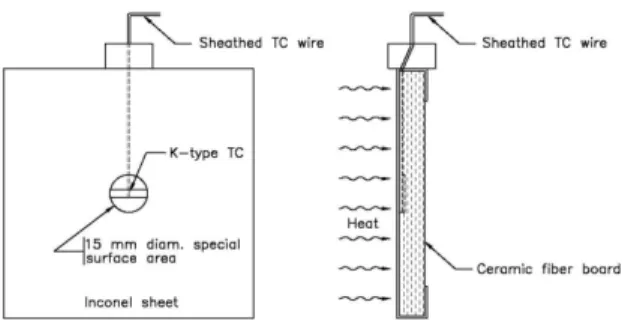
The temperature sensors used in this study comprises of 5 shielded thermocouples, 5 plate thermometers, 5 directional flame thermometers, 5 bare-bead thermocouples, 5 grounded sheathed thermocouples and 5 ungrounded sheathed thermocouples. Only the shielded and bare-bead thermocouples were fabricated in-house while all other sensors were bought commercially. The sensor descriptions are given below. ASTM Shielded Thermocouples – The shielded thermocouple was fabricated in accordance with the ASTM E119 standard by fusing the twisted ends of No. 18 gauge Chromel-Alumel wires, and mounting the leads inside a porcelain insulator. The thermocouple with the porcelain insulator was inserted inside a 12.7 mm diameter Inconel 600 tube so that the thermocouple bead was 12.7 mm away from a sealed end steel cap. The shielded thermocouple is schematically shown in Figure 1.
ISO 834 Standard Plate Thermometers – The plate thermometer consists of a 100 mm by 100 mm Inconel 600 plate, 0.7 mm thick, with a surface emissivity greater than 0.7. A Type K, 1 mm diameter sheathed thermocouple is held against the centre of the back side of the plate. This side faces the test specimen and is insulated with10 mm thick ceramic fibreboard. The front side of the plate faces the furnace. A schematic of the plate thermometer is shown in Figure 2. These thermocouples were made by
Thermo-Electra based on the description in Reference4. The plate thermometer temperature reading can be used to
estimate the total incident heat flux based on the adiabatic temperature methodology9.
Directional Flame Thermometers – The directional flame thermometer consists of two 120 mm by 120 mm Inconel plates, 3 mm thick. Ceramic fibre insulation 19 mm thick is sandwiched between the two plates. Two sheathed Type K thermocouples with ungrounded junction are attached to the unexposed faces of the Inconel plate with a thin Nichrome foil spot-welded over the tip of the thermocouples. The
exposed surfaces of the Inconel plates are coated with Pyromark 2500 black10 or are heavily oxidized11 to
provide consistent radiation properties. The time constant for the directional flame thermometers is
estimated at approximately 89 seconds at the start of the test12. A schematic of the directional flame
thermometer is shown in Figure 3. The directional flame thermometer temperature readings of both sides
can be used to estimate the total incident heat flux using the inverse heat conduction code13.
Bare-Bead Thermocouples – The bare-bead thermocouple was fabricated by fusing the twisted ends of 20 gauge Chromel-Alumel wires to form a thermocouple bead with 2 mm diameter. Bare-bead thermocouples are usually used in extremely fast response time as required and in an environment of non corrosive gases or liquids. In fire resistance testing, where the hot gas temperature exceeds 1000 ºC, the bare-bead thermocouples do not last for many tests.
Grounded Sheathed Thermocouples – The grounded sheathed thermocouple12, shown in Figure 4, consists
of a closed end Inconel tube sheathing, 6.5 mm O.D., with Type K (20 gauge) Chromel-Alumel wires. The wires were inserted inside the inconel sheath tube and the junction of the thermocouple was welded to the protective sheath tube end . As the thermocouple sheath is made from Inconel, it provides stiffness and durability in harsh environments such as in fire resistance tests. This type of thermocouples can be used where fast response is required and because of their sheath protection, they can be used in an unusual harsh environment such as in fire resistance furnaces.
Ungrounded Sheathes Thermocouples – The ungrounded sheathed thermocouples12 of Inconel tube 6.5 mm O.D. are similar to those grounded sheathed thermocouples, except that the thermocouples wire junction is not connected to the protective sheath tube end as shown in Figures 5. As this type of thermocouple is not in contact with the sheath, it is usually used where fast response time is required and in an environment where electrical noise exists.
The sensors were placed in 5 clusters in both wall and floor furnaces: one cluster was placed at the centre of the furnace and each of the remaining 4 clusters were placed at the centre of the quarter section of the furnace. Each cluster has 6 different sensors and they were placed as close as possible to each other. All temperature sensor clusters were located 100 mm away from the furnace cover specimen in both wall and
floor furnaces except the shielded thermocouples which were placed at 300 mm in accordance to ASTM1.
Heat Flux Sensor
Five heat flux sensors, water-cooled Gardon Gauge, were used to measure the incident heat to a test specimen in the full-scale wall and floor furnaces. These gauges are 25 mm in diameter and 25 mm long copper cylinders and have a stated accuracy of ±3%. The cooling water flow temperature was maintained during the entire test within the temperature range specified by the manufacturer for the sensors.
Full-scale Floor and Wall Furnaces
A full-scale fire resistance floor furnace is approximately 3.9 m wide by 4.8 m long by 3 m deep and the wall furnace is 3.6 m wide by 3 m high by 0.5 m deep In the floor furnace, the furnace walls were made of insulated firebrick while in the wall furnace, the furnace walls were covered with a ceramic fibre blanket. Details on these furnaces can be found in Reference 15.
Experimental Procedure
The furnace temperature and heat exposure measurements for 12 experiments were collected. The duration of each experiment was 1 hour and the data was recorded every 10 seconds. Six experiments were conducted using a floor furnace and six experiments were conducted using a wall furnace. In each experiment, the furnace was controlled by an average of 5 temperature sensors of the same kind and incident heat flux was measured as well, while all other temperature sensor readings were recorded for comparison. The wall and floor furnaces are controlled electronically in such a way that the furnace temperature follows as closely as possible to the AST E119 standard temperature curve.
RESULTS AND DISCUSSION
The main mechanisms of heat transfer in the fire resistance test furnaces are by radiation and to a certain extent by convection. The radiation heat transfer depends on the furnace hot gases temperature and emissivity as well as on the thermal conductivity and emissivity of furnace lining material. The use of lining material with very low thermal conductivity results in the furnace lining surface temperature being
close to the hot gases temperature. This helps the harmonization among different furnaces15. The
convective heat transfer depends in part on the furnace size and location of furnace burners and hot gases exit ports. In a larger furnace, convective heat transfer is primarily by natural convection where the burners are away from test specimen; however, in a shallow furnace such as a wall furnace, the convective heat transfer could be dominated by forced convection due to its proximity to the burners. It is important to use a temperature-measuring device that senses both convective and radiation components with a small response time constant. The results of the 12 experiments are discussed below.
Furnace Temperature Measurements
Furnaces Controlled by Shielded Thermocouple Probes – Two experiments were conducted: one using the floor furnace with a 2.4 m depth and the other using a wall furnace with a 0.5 m depth. In the ASTM E119 standard time-temperature curve, the rate of temperature increases more rapidly in the first 10 minutes than in the remainder of the curve.
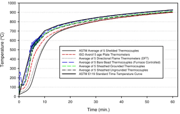
In the first experiment, the floor furnace temperature was controlled by an average of five-shielded thermocouple probes to follow the ASTM E119 time – temperature curve. A comparison of the average furnace temperatures measured with the six different types of sensors is presented in Figure 6. The results are consistent with the response time characteristics of the sensors. The furnace temperature rises rapidly at the start to follow the steep part of the standard temperature curve. During this initial period, approximately 8 minutes, the bare-bead thermocouples reading increases at the fastest rate followed by the grounded and ungrounded sheathed thermocouples and by the plate thermometers. This is in part due to a small time constant of less than 1 minute for these temperature sensors. On the other hand, the reported temperature of the shielded thermocouple probe with the largest time constant, increased at the slowest rate. However, the directional flame thermometer was somewhat faster than the shielded thermocouples and this is also related in part to the time constant where the later has the second largest time constant. After approximately 8 to 10 minutes, the furnace temperature for all sensors starts to level off and then converge. This could also be explained as the rate of furnace temperature rise is starting to level off, the temperature measurement response time becomes relatively insignificant and all sensor measurements are converging. This is consistent with the ASTM E119 standard time-temperature curve, the rate of temperature increases rapidly in the first 10 minutes than the remainder part of the curve. However, the bare-bead thermocouple readings continue to be higher for the remainder of the test. This is due to the fact that the ratio of convective vs. radiative heat transfer is higher for the bare-bead thermocouples compared to the other sensors.
In the second experiment, the wall furnace was controlled by an average of 5 shielded thermocouple probes. A comparison of the temperature measured by the different sensors is shown in Figure 7. Unlike the temperature measured in the floor furnace during the first 10 minutes, all sensor readings were erratic except for the shielded thermocouples. In part this was due to the automatic turning off of the furnace, as it attempted to follow the ASTM E119 curve, when the temperature measured by the shielded thermocouples started to move higher than the standard curve. This in part is due to aspects of the furnace design as well as to the programming of the furnace controller and limitation on control of the fuel gas flow, such as a shorter depth and burner flames that are closer to the sensors than is the case for the floor furnace. However, there are similar trends for temperature measured by the different sensors to those measured in the floor furnace. The bare-bead thermocouple also measured the highest temperature and this, once again, is due to the time constant of such sensors. After approximately 10 minutes, all sensors start to level off, as the standard temperature starts to level off, and then converge similarly to the response in the floor furnace. The results measured by the different sensors indicate that the temperature measurements in fire resistance test furnaces, even with different depths, depend on the time constant of the temperature measurement sensor particularly in the first 10 minutes.
For an application requiring a shorter fire resistance test, such as a 15 minute test, thermal exposure is more severe in a test controlled by shielded thermocouple probes than those controlled by other sensors. These results could be of interest for the standard writing organization consideration in short duration fire resistance tests.
Furnaces Controlled by the Plate Thermometers – Two experiments were conducted where the floor and wall furnaces were controlled by the plate thermometers to follow the ASTM E119 standard time-temperature curve. The first experiment was carried out using the floor furnace. A comparison of the average furnace temperatures measured with six different sensors is presented in Figure 8. In the first 10 minutes, as in the case where the furnace is controlled by shielded thermocouples, the bare-bead thermocouples and grounded and ungrounded sheathed thermocouples temperaturse, due to their shorter time constant, are higher than the other sensors. However, the shielded thermocouple probes and the directional flame thermometer temperatures are lower than the plate thermometers and this is also due to the larger time constant for those sensors compare to the plate thermometer time constant. After 10 minutes, all sensors start to level off as the standard temperature starts to level off and then converge and this is similar to the response in the floor furnace when the furnace is controlled by the shielded
thermocouples. The results are consistent with the response time characteristics of the six sensors and their sensitivity to convective vs. radiative heat transfer as discussed in the previous section. In the second experiment, the wall furnace was controlled by the plate thermometers. A comparison of the average furnace temperatures measured with six different sensors is presented in Figure 9. A similar temperature trend was shown for all six sensors as in the case above for floor furnace during the entire experiment. The temperatures measured by the grounded and ungrounded sheathed thermocouples are similar and their differences, with respect to the bare-bead thermocouple temperature, were the smallest. The furnace size did not create erratic temperature distributions in the first 10 minutes as seen above when the furnace was controlled by the shielded thermocouple and this is due to a shorter time constant for the plate thermometer.
Furnaces Controlled by the Directional Flame Thermometers – Two experiments were also conducted with furnaces controlled by the directional flame thermometers: one with a floor furnace and the other with a wall furnace. In these experiments, the average of five directional flame thermometers were used to control the furnace in such a way that the furnace temperature is following the ASTM E119 time – temperature curve. Comparisons of the furnace average temperatures measured with four types of sensors are presented in Figures 10 (floor furnace) and 11 (wall furnace). The results showed that in the first 10 minutes, the bare-bead, grounded, ungrounded sheathed thermocouples and plate thermometers measured higher temperatures, except the shielded thermocouple, which was lower than the directional flame thermometer. This was also due to the time constant as explained before. The temperatures measured by the grounded and ungrounded sheathed thermocouples are similar and their differences, with respect to the bare-bead thermocouple temperature, were small. The results are also consistent with the response time characteristics of the sensors and their sensitivity to convective vs. radiative heat transfer as discussed in previous sections. After 10 minutes, all sensors start to level off as the standard temperature starts to level off and then converge. This is similar to the response in the floor furnace when the furnace is controlled by the shielded thermocouples and by the plate thermometers.
Furnaces Controlled by the Bare-Bead Thermocouples – Two experiments were conducted using the floor and wall furnaces. The furnaces were controlled by five bare-bead thermocouples to follow the ASTM E119 time – temperature curve. Comparisons of the furnaces’ average temperature, measured with six types of sensors is presented in Figures 12 (floor) and 13 (wall). Since the bare-bead thermocouples have a fastest response time, using them to control the furnace, especially in the first 10 minutes of experiment, was a challenge. During the first 10 minutes of the test, only the grounded and ungrounded sheathed thermocouples measured approximately similar temperatures to the bare-bead thermocouples and the shielded thermocouple probes. The directional flame thermometers and plate thermometers are all measuring lower temperature than the bare-bead thermocouple by 75%, 65% and 50%, respectively. This is because the time constant for these three sensors are larger than those of the bare-bead thermocouples. After 10 minutes of fire exposure, the three sensors measured more or less the same temperature; however, these were lower by 8% than the bare-bead thermocouples. After 10 minutes, all sensors started to level off as the standard temperature started to level off, and then converge.
Furnaces Controlled by the Grounded Sheathed Thermocouples – Two experiments were conducted where the floor and wall furnaces were controlled by the grounded sheathed thermocouples to follow the ASTM E119 standard time-temperature curve. The first experiment was carried out using the floor furnace. A comparison of the average furnace temperatures measured with six different sensors is presented in Figure 14. In the first 10 minutes, as in the cases above for other controlled sensors, the bare-bead thermocouples are slightly higher than the grounded sheathed thermocouples. All other sensors, except the ungrounded sheathed thermocouples, measured lower temperatures; however, there is not much difference in the temperature measured by either the grounded and ungrounded sheathed thermocouples. This is due to their shorter time constant compared to the plate thermometer, shielded thermocouples and directional flame thermometers. After 10 minutes, all sensors start to level off as the standard temperature starts to level off, and then converge and this is similar to the response in the floor
furnace when the furnace was controlled by the shielded thermocouples. The results are consistent with the response time characteristics of the six sensors and their sensitivity to convective vs. radiative heat transfer as discussed in the previous section. In the second experiment, the wall furnace was controlled by the plate thermometers. A comparison of the average furnace temperatures measured with six different sensors is presented in Figure 15. Similar temperature trend was shown for all six sensors as in the case above for floor furnace during the entire experiment. The temperatures measured by the grounded and ungrounded sheathed thermocouples are similar, and their differences with respect to the bare-bead thermocouple temperature were the smallest, therefore, they provided faster response than the plate thermometers.
Furnaces Controlled by the Ungrounded Sheathed Thermocouples – Two experiments were conducted where the floor and wall furnaces were controlled by the ungrounded sheathed thermocouples to follow the ASTM E119 standard time-temperature curve. The first experiment was carried out using the floor furnace. Comparisons of the average furnace temperatures measured with six different sensors are presented in Figure 16 for the floor furnace and Figure 17 for the wall furnace. The temperature results are similar to those measured in furnaces controlled by grounded sheathed thermocouples. The temperature measured by either the bare-bead, grounded and ungrounded sheathed thermocouples are more or less similar.
Temperature Lag with Respect to Bare-Bead Thermocouples Measurements
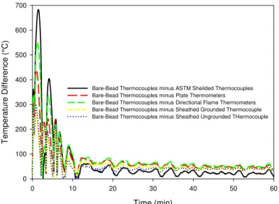
The bare-bead thermocouples have the smallest time response among the other temperature sensors. To quantify temperature lag between the bare-bead thermocouple measurements and all other temperature sensors, the temperature measurements of the ASTM shielded thermocouples, ISO plate thermometers, directional flame thermometers, grounded and ungrounded sheathed thermocouples were subtracted from the bare-bead thermocouple measurements in the tests where these sensors were used to control the floor and wall furnaces. The time lag is plotted in Figures 18 and 19 for the floor furnace and wall furnace, respectively. The results show that, in the first 10 minutes, the temperature lag is significant, but after 10 minutes, the temperature lag becomes insignificant. However, a relatively small temperature bias remains after 10 minutes due to differences of the sensors’ sensitivity to convective versus radiative heat transfer. In both floor and wall furnaces, the temperature lag for the grounded and ungrounded thermocouples is the smallest followed by the plate thermometers, directional flame thermometers and the largest is the ASTM shielded thermocouples. The difference in the temperature lag is due in part to the difference in the temperature response time of these sensors compared to the bare-bead thermocouples.
Incident Heat Flux Measurements
The incident heat flux measured for floor and wall furnaces, where the furnaces are controlled by one of the six temperature sensors, are presented in Figures 20 and 21, respectively. The incident heat flux results showed that for the furnace controlled by the shielded thermocouples the heat flux are approximately up to 20% more than the furnace controlled by bare-bead thermocouples. For furnaces controlled by the grounded and ungrounded thermocouples, the incident heat flux is approximately 5% more than the furnaces controlled by the bare-bead thermocouples. These differences are due to differences in the time constant of different types of temperature sensors.
SUMMARY
This paper discusses the performance of six different temperature sensors for controlling the furnace temperature in a floor furnace and a wall furnace, as well as, the temperature lag for ASTM shielded thermocouples, plate thermometers, directional flame thermometers and grounded and ungrounded sheathed thermocouples in comparison to the bear-bead thermocouples. It also discusses the incident heat flux in floor and wall furnaces. The following are the key findings:
1. In fire resistance furnaces of different depths, the initial period of fire exposure (10 minutes) results in significant differences in the temperature measured by the six sensors. However, after 10 minutes, the
differences become insignificant. This indicates that the furnace temperature measuring device response time is crucial in assessing building elements performance particularly in a short duration tests.
2. Because the Inconel grounded and ungrounded thermocouples have a fast response time and durability, they could be good potential sensors for use in fire resistance standard test furnaces.
3. A deeper furnace is easier to control in its initial rapid temperature rise than a shallow furnace.
ACKNOWLEDGEMENTS
The author wishes to thank Jocelyn Henrie and Yves Seguin of the Fire Research Program, National Research Council of Canada for their help in conducting the experimental work.
REFERENCES
1. ASTM E119-08, “Standard Methods of Fire Tests of Building Constructions and Materials”, ASTM, Philadelphia, PA.
2. ISO 834-1, “Fire Resistance Tests Elements of Building Construction – Part 1”
3. CAN/ULC-S101-07, “Standard Methods of Fire Endurance Tests of Building Construction and Materials” ULC, Toronto, Ontario Canada
4. Wickström, U.,”The Plate Thermometer – Practical Aspects”, SP- Report 1997:28, Swedish National Testing and Research Institute, 1997.
5. The European Standard EN 1363-1:1999, “Fire Resistance Tests – Part 1: General Requirements”, European Committee for Standardization, rue de Stassart 36, B-1050 Brussels, 1999.
6. Sultan, M.A. “Fire Resistance Furnace Temperature Measurements: Plate Thermometers vs. Shielded Thermocouples”, Fire Technology, 2008.
7. Sultan, M.A. “Comparisons of Temperature and Heat Flux in Furnaces Controlled by Different Types
of Temperature Sensors” Published online, Journal of ASTM International, 100 Barr Harbor Drive, PO Box C700, West Conshohocken, PA 19428-2959, 2009.
8. Babrauskas, V. and Williamson, R.B. “Temperature Measurement in Fire Test Furnaces”, Fire Technology, Vol.14, No. 3, 1978.
9. Wickström, U. “Adiabatic Surface Temperature and the Plate Thermometer for Calculating Heat Transfer and Controlling Fire Resistance Furnaces” Fire Safety Science Proceedings of Ninth International Symposium, 2008.
10. Longenbaugh, R.S. et al. Thermal Response of a Small Scale Cask-Like Test Article to Three Different High Temperature Environments”, Sandia National Laboratories Report to Federal Rail Administration, DOT/FRA/ORD- 90/01, Feb. 1990.
11. Keltner, N.R. “Directional Flame Thermometers: A Tool for Measuring Thermal Exposure in Furnaces and improving Control” Interflam 2007, Proceedings of the Eleventh International Conference, Interscience Communications, 2007.
12. Keltner, Ned, private communication 2008.
13. The Temperature Handbook, OMEGA Engineering Inc., Vol. 20, Page A-7, P.O. Box 4047, Stamford, CT 06907-0047, USA
14. Shorter, G.W. and Harmathy, T.Z. “Fire Research Furnaces at the National Research Council, NRC 5732, National Research Council Canada, Ottawa, Ontario, Canada 1960.
15. Sultan, M.A. and Denham, M. “Harmonization of Fire Severity in Standard Fire Resistance Test Furnaces”, Fire Safety Sciences – Proceedings of the Fifth International Symposium, 1997.
Figure 1. ASTM E119 Shielded Thermocouple Figure 2. ISO 834 Plate Thermometer
Figure 3. Directional Flame Thermometer Figure 4. Grounded Sheathed Thermocouple
Figure 5. Ungrounded Sheathed Thermocouple
T h e r m o c o u p l e J u n c t i o n A l u m e l C h r o m e l I n c o n e l U p p e r i n c o n e l p l a t e 4 x , 1 / 4 - 2 0 x 1 . 5 0 S S H e x h e a d s c r e w s a n d n u t s T y p e K T C , o n e p e r p l a t e L o w e r i n c o n e l p l a t e T y p e K T Co n e p e r p l a t e 4 x , 3 / 8 O D x 0 . 2 7 7 I D x 0 . 7 5 l o n g , S S s p a c e r C e r a b l a n k e t T h e r m o c o u p l e J u n c t i o n A l u m e l I n c o n e l C h r o m e l
Time (min.) 0 10 20 30 40 50 60 T e m per at ure (°C) 0 100 200 300 400 500 600 700 800 900 1000
ASTM Average of 5 Shielded Thermocouples (Furnace Controlled) ISO Average of 5 Plate Thermometers
Averaghe of 5 Directional Flame Thermometers Average of 5 Bare-Bead Thermocouples Average of 5 Grounded Sheathed Themocouples Average of 5 Ungrounded sheathed Thermocouples ASTM Standard Time-Temperature Curve
Time (min.) 0 10 20 30 40 50 60 T e mperat ur e (°C ) 0 100 200 300 400 500 600 700 800 900 1000
ASTM Average of 5 Sheilded Thermocouples (Furnace Controlled) ISO Average of 5 Plate Thermometers
Average of 5 Directional Flame Thermometers Average of 5 Bare-Bead Thermocouples Average of 5 Grounded Sheathed Thermocouples Average of 5 Ungrounded Sheathed Thermocouples ASTM E119 standard Time-Temperature Curve
Figure 6. Floor Furnace controlled by Shielded Thermocouples. Figure 7. Wall Furnace Controlled by Shierlded Thermocouples.
Time (min.) 0 10 20 30 40 50 60 T e m perat ure ( °C) 0 100 200 300 400 500 600 700 800 900 1000
ASTM Average of 5 Sheilded Thermocouples ISO Average of 5 Plate Thermometers (Furnace Controlled) Average of 5 Directional Flame Thermometers Average of 5 Bare-Bead Thermocouples Average of 5 Grounded Thermocouples Average of 5 Ungrounded Thermocouples ASTM Standard Time-Temperature Curve
Time (min.) 0 10 20 30 40 50 60 T e mp er atu re ( °C) 0 100 200 300 400 500 600 700 800 900 1000
ASTM Average of 5 Sheilded Thermocouples ISO Average of 5 Plate Thermometers (Furnace Controlled) Average of 5 Directional Flame Thermometers Average of 5 Bare-Bead Thermocouples Average of 5 Grounded Sheathed Thermocouples Average of 5 Sheathed Ungrounded Thermocouples ASTM E119 Standard Time-Temperature Curve
Figure 8. Floor Furnace controlled by Plate Thermometers. Figure 9. Wall Furnace Controlled by Plate Thermometers.
Time (min.) 0 10 20 30 40 50 60 Temper atur e (° C) 0 100 200 300 400 500 600 700 800 900 1000
ASTM Average of 5 Sheilded Thermocouples ASO Average of 5 Plate Thermometers
Average of 5 Directional Flame Thermometers (Furnace Controlled) Average of 5 Barwe-Bead Thermocouples
Average of 5 Grounded Sheathed Thermocouples Average of 5 Ungrounded Sheathed Thermocouples ASTM E119 Stanadarad Time-Temperature Curve
Time (min.) 0 10 20 30 40 50 60 Temper atur e (° C) 0 100 200 300 400 500 600 700 800 900 1000
ASTM Average of 5 Sheilded Thermocouples ISO Average of 5 Plate Thermometers
Average of 5 Directional Plate Thermometers (Furnace Controlled) Average of 5 Bare-Bead Thermocouples
Average of 5 Grounded Sheathed Thermocouples Average of 5 Ungrounded Sheathed Thermocouples ASTM E119 Standard Time-Temperature Curve
Time (min.) 0 10 20 30 40 50 60 T em per at ure (° C ) 0 100 200 300 400 500 600 700 800 900 Time (min.) 0 10 20 30 40 50 60 Temper atur e (° C) 0 100 200 300 400 500 600 700 800 900 1000
ASTM Average of 5 Sheilded Thermocouples ISO Averof 5 age Plate Thermometers Average of 5 Directional Flame Thermometers (DFT) Average of 5 Bare Bead Thermocouples (Furnace Controlled) Average of 5 Sheathed Grounded Thermocouples Average of 5 Sheathed Ungrounded Thermocouples ASTM E119 Standard Time-Temperature Curve
1000
ASTM Average of 5 Sheilded Thermocouples ISO Average of 5 Plate Thermometers Average of 5 Directional Flame Thermometers Average of 5 Bare-Bead Thermocouples (Furnace Controlled) Average of 5 Grounded Sheathed Thermocouples Average of 5 Ungrounded Sheathed Thermocouples ASTM E119 Standard Time-Temperature Curve
Figure 12. Floor Furnace Controlled by Bare-Bead Thermocouples. Figure 13. Wall Furnace Controlled by Bare-Bead Thermocouples.
Time (min.) 0 10 20 30 40 50 60 T em perat ure ( °C ) 0 100 200 300 400 500 600 700 800 900 1000
ASTM Average of 5 Sheilded Thermocouples ISO Average of 5 Plate Thermometers Average of 5 Directional Flame Thermometers (DFT) Average of 5 Bare-Bead Thermocouples
Average of 5 Grounded Sheathed Thermocouples (Furnace Controlled) Average of 5 Ungrounded Sheathed Thermocouples ASTM E119 Standard Time-Temperature Curve
Time (min.) 0 10 20 30 40 50 60 Temper atur e (° C) 0 100 200 300 400 500 600 700 800 900 1000
ASTM Average of 5 Sheilded Thermocouples ISO Average of 5 Plate Thermometers Average of 5 Directional Flame Thermometers Average of 5 Bare-Bead Thermocouples
Average of 5 Grounded Sheathed Thermocouples (Furnace Controlled) Average of 5 Ungrounded Sheathed Thermocouples ASTM E119 Standard Time-Temperature Curve
Figure 14. Floor Furnace Controlled by Grounded Sheathed Thermocouples. Figure 15. Wall Furnace Controlled by Grounded Sheathed Thermocouples.
Time (min.) 0 10 20 30 40 50 60 Tem perat ure (°C) 0 100 200 300 400 500 600 700 800 900 1000
ASTM Average of 5 Sheilded Thermocouples ISO Average of 5 Pltae Thermometers Average of 5 Directional Flame Thermometers Average of 5 Bare-Bead Thermocouples Average of 5 Grounded Sheathed Thermocouples
Average of 5 Ungrounded Sheathed Thermocouples (Furnace Controlled) ASTM E119 Standard Time-Temperature Curve
Time (min.) 0 10 20 30 40 50 60 Te m p er a tur e (° C) 0 100 200 300 400 500 600 700 800 900 1000
ASTM Average of 5 Sheilded Thermocouples ISO Average of 5 Plate Thermometers Average of 5 Directional Flame Thermometers Average of 5 Bare-bead thermocouples Average of 5 Grounded Thermocouples
Average of 5 Ungrounded Thermocouples (Furnace Controlled) ASTM E119 Standard Time-Temperature Curve
Time (min) 0 10 20 30 40 50 60 T e mp er at ur e Di ff er en c e ( °C) 0 100 200 300 400 500 600 700
Bare-Bead Thermocouples minus ASTM Sheilded Thermocouples Bare-Bead Thermocouples minus Plate Thermometers Bare-Bead Thermocouples minus Directional Flame Thermometers Bare-Bead Thermocouples minus Sheathed Grounded Thermocouple Bare-Bead Thermocouples minus Sheathed Ungrounded THermocouple
Figure 18. Differences between Bare-Bead and Other Sensors (Floor Furnace). Figure 19. Differences between Bare-Bead and Other Sensors (Wall Furnace).
Time (min.) 0 10 20 30 40 50 60 H e at Fl ux ( k W /m 2 ) 0 20 40 60 80 100 120 140 160
Furnace Controlled with ASTM Sheilded Thermocouples Furnace Controlled with ISO Plate Thermometers Furnace Controlled with Directional Flame Thermometers Furnace Controlled with Bare-Bead Thermocouples Furnace Controlled with Grounded Thermocouples Furnace Controlled with Ungrounded Thermocouples
Figure 20. Incident Heat Flux in Floor Furnace. Figure 21. Incident Heat Flux in Wall Furnace. Time (min) 0 10 20 30 40 50 60 T e m perat ure Dif ference (°C) 0 100 200 300 400 500 600 700
Bare-Bead Thermocouples minus ASTM Sheilded Thermocouples Bare-Bead Thermocouples minus Plate Thermometers Bare-Bead Thermocouples minus Directional Flame Thermometers Bare-Bead Thermocouples minus Sheathed Grounded Thermocouples Bare-Bead Thermocouples minus Sheathed Ungrounded Thermocouples
Time (min.) 0 10 20 30 40 50 60 H e at Fl ux ( k W /m 2 ) 0 20 40 60 80 100 120 140 160
Furnace Controlled with ASTM Sheilded Thermocouples Furnace Controlled with ISO Plate Thetrmometers Furnace Controlled with Directional Flame Thermometers Furnace Controlled with Bare-Bead Thermocouples Furnace Controlled with Grounded Sheathed Thermocouples Furnace Controlled with Ungrounded Sheathed Thermocouples