Analysis of ICRF heated discharges
wi th boron coated molybdenum tiles
The MIT Faculty has made this article openly available.
Please share
how this access benefits you. Your story matters.
Citation
Wukitch, S. J., M. Garrett, H. Barnard, B. LaBombard, Y. Lin, B.
Lipschultz, E. Marmar, R. Ochoukov, M.L. Reinke, D.G. Whyte, G.H.
Wright, and the AlcatorC-Mod Team. "Analysis of ICRF heated
discharges with boron coated molybdenum tiles." In 37th European
Physical Society Conference on Plasma Physics, Dublin, Ireland, 21
-25 June, 2010. (Europhysics Conference Abstracts; vol. 34A). P5.194.
As Published
http://ocs.ciemat.es/EPS2010PAP/pdf/P5.194.pdf
Publisher
European Physical Society
Version
Author's final manuscript
Citable link
http://hdl.handle.net/1721.1/81758
Terms of Use
Creative Commons Attribution-Noncommercial-Share Alike 3.0
Detailed Terms
http://creativecommons.org/licenses/by-nc/3.0/
Analysis of ICRF heated discharges with boron coated molybdenum tiles
S.J. Wukitch, M. Garrett, H. Barnard, B. LaBombard, Y. Lin, B. Lipschultz, E. Marmar, R.Ochoukov, M.L. Reinke, D.G. Whyte, G.H. Wright, and the AlcatorC-Mod Team
MIT Plasma Science and Fusion Center, Cambridge, MA 02139, USA
Minimizing impurity production associated with ion cyclotron range of frequency (ICRF) operation to an acceptable level in H-mode, particularly with metallic plasma facing components (PFC), is challenging. To identify important erosion and impurity source locations, we have vacuum plasma sprayed ~100 μm of boron (B) onto molybdenum (Mo) tiles. For ICRF heated H-modes, the core molybdenum levels have been significantly reduced and remained at low levels for increased injected RF energy. The core Mo level also no longer scales with RF power in L-mode. With boronization and impurity seeding (typically nitrogen or neon), the plasma and ICRF antenna performance were improved. Surprisingly, impurity seeding did not result in increased core Mo levels and also suppressed antenna faults. Spectroscopic monitoring of the plasma limiter found that the impurity profile at the limiter was centered near the plasma mid-plane and the profile did not change shape with plasma current. From post campaign inspection, the B coating was not significantly eroded except in locations where melting occurred or where it peeled. Trace material analysis also found that the B surface was contaminated with Mo and tungsten (W). Improved performance with impurity seeding, the lack of erosion, and metallic contamination of the B coating suggest ICRF impurity generation is related localized heat loads (that can lead to melting) rather than entirely a result of sputtering.
Experimental Background and Setup
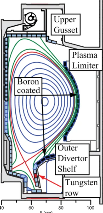
Although ICRF heating is considered an excellent candidate for bulk heating, impurity production associated with ICRF operation can degrade H-mode performance, particularly with metallic plasma facing components (PFC).[1,2] To control impurities, boronization, an in-situ applied boron film, is often utilized but its lifetime is limited. In C-Mod, the lifetime has been observed to be proportional to integrated injected RF Joules (~50 MJ) and degrades faster than in equivalent ohmic heated discharges.[1] To identify significant erosion and impurity source locations, ~100 μm of B has been vacuum plasma sprayed (typical overnight boronization applies ~0.2 μm) onto Mo tiles from the outer divertor shelf, main plasma limiters, and the RF antennas, see Figure 1. The B is applied in an argon atmosphere and the Mo substrate is at an elevated temperature, about 600 °C.[3]
The Alcator C-Mod discharges analyzed here are H-minority heated D discharge where the H cyclotron resonance is located near the magnetic axis.[4] Up to 5 MW of ICRF power is coupled to the plasma via three fast wave antennas.[5,6] In addition to standard plasma temperature and density diagnostics, core Mo content is monitored at Mo XXXI (11.6 nm) using a 2.2 meter grazing-incidence Rowland circle spectrometer. The local impurity line emission at the plasma limiter is monitored along 24 views as shown in Figure 2. The Mo I line and B I line are monitored at 386.4 nm and 419 nm respectively using an f/4, 0.25 m visible spectrometer.
Inspection of the B coating was performed both prior to and post operation. To monitor gross changes, an eddy current lift off technique measures the boron coating thickness and can be done in-situ. Simple visual inspection is also performed to monitor for spall and melt damage. For trace contaminants, proton induced x-ray emission (PIXE) is utilized. Briefly, PIXE uses a ~2 MeV proton beam to cause ionization of near surface atoms leading to X-ray emission from the K and L shell electrons, which are used for identifying elements (Z > 20).[7]
Experimental Results
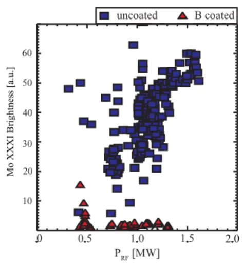
To investigate the impact the B coating had on plasma performance and core Mo content, a series of L and H-mode discharges were run. For L-mode, upper single null discharges were utilized to raise the H-mode threshold (∇B away from the X-point). In these discharges, the core Mo levels no longer scaled with RF power, in contrast with previous results with boronization and Mo plasma facing components, see Figure 3. For H-modes, a series of discharges were run following an
overnight boronization to evaluate the core Mo content and rate of plasma performance degradation with injected RF energy. As shown in Figure 4, the core Mo levels were significantly reduced and remained at low levels for increased integrated injected RF Joules. To investigate the impact on plasma performance, a boronization was appled, followed by a
C G D 40 60 80 100 R (cm) Upper Gusset Plasma Limiter Outer Divertor Shelf Tungsten row Boron coated
Figure 1: Boron coated tiles
are located on the plasma limiter, RF limiters (not shown and at larger major radius than the plasma limiter), and outer divertor tiles.
Figure 2: The main plasma
limiter has 24 spectroscopic views of which 16 can be monitored simultaneously.
series of consistent discharge until the confinement degraded. As shown in Figure 5, the confinement was still reasonable after ~100 MJ of injected RF power, whereas without B coated tiles the confinement had degraded at ~50 MJ of RF power.
In experiments to investigate compatibility of high radiative fraction and H-mode performance, nitrogen or neon impurity seeding of the H-mode improved the plasma and ICRF antenna performance. Surprisingly, impurity seeding did not dramatically increase the core Mo levels and also suppressed antenna faults due to arcs and injections from the antenna structure. A comparison of two discharges, shown in Figure 6, where one is seeded throughout the discharge (red) and the other (blue) is seeded until 1.1 s, illustrates the improved antenna performance. An expected result from the impurity seeding was an increase in the core Mo level since Mo sputtering should increase with the addition of a medium-Z, recycling impurity.
With new spectroscopic views of the plasma
limiter, we sought to characterize the molybdenum and boron source at the plasma limiter. This limiter is ~1 cm closer to the last closed flux surface than the RF antenna limiters and is magnetically connected to the 4 strap antenna. As expected, B I dominates Mo I
for the B coated tiles on the limiter. The count profile is peaked at the plasma mid-plane where the plasma is closest to the limiter due to magnetic geometry. Although the limiter maps to the 4-strap antenna, the profile shape is unchanged with plasma current suggesting the profile shape is not dominated by sputtering from RF enhanced sheaths. In H-mode, the maximum counts are weakly dependent upon the RF power; however, the impurity source is clearly enhanced in RF heated H-modes compared to ohmic H-modes as shown in Figure 7.
Prior to operation the boron coating thickness was measured in-situ by an eddy current technique. We used a Hocking Phasec2d and calibrated it against uncoated Mo tiles
0 0.5 1.0 1.5 2.0 PRF [MW] 60 50 40 30 20 10
Mo XXXI Brightness [a.u.]
uncoated B coated
Figure 3: Core Mo brightness independent
of RF power with the B coated Mo tiles.
20 40 60 80
RF Input Energy Since BZN [MJ] with Boron coated tiles without Boron coated tiles
Moly Brightness/n e 0 0 20 40 60 80 100 120
Figure 4: Core Mo is significantly reduced
and increases slower for integrated coupled RF joules for the B coated Mo case.
0 20 40 60 80 100
RF Input Energy Since BZN [MJ] 0.0 0.5 1.0 1.5 2.0 H89
with Boron coated tiles without Boron coated tiles
Figure 5: Plasma performance as measured
by plasma confinement is maintained for increased integrated injected RF Joules.
and known standards. The small size of the head allowed for average thickness of the coating to be found. The same technique was used following the campaign. No discernable erosion of the tiles was observed. Based upon erosion estimates from previous experiments (15-20 nm/s of ICRF), we expected between 20-30 μm to be eroded. Aside from tiles where the B clearly peeled, likely due to poor thermal contact, the B coating thickness appeared to be unchanged. The peeled tiles also did not show a discernable pattern: the neighbors of peeled tiles showed no signs of degradation or peeling in many cases.
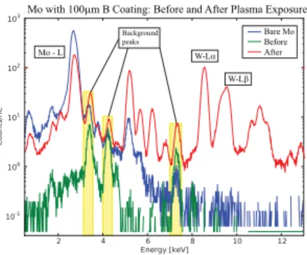
Using PIXE technique, we investigated the surface contaminates on the exposed B coated tiles. Calibration data were taken on samples of stainless steel, W, Mo, and an unexposed B coated Mo tile. As shown in Figure 8, the exposed B coated tiles clearly have Mo and W contamination. Despite the preliminary nature of the data, the amounts of W and Mo are more than an order of magnitude higher than other previous W contamination when W erosion was sputtering dominated (melted W and Mo tiles were confirmed after the campaign). The Mo and W contamination on top of B film, lack of B film erosion, and improved plasma and antenna performance suggest impurity production is related to localized heat loads that can result in melting rather than entirely from sputtering.
Acknowledgements
Work was supported by US Depart. of Energy, Coop. Agreement No. DE-FC02-99ER54512.
References
1
B. Lipschultz et al., Phys. Plasmas 13, 056117 (2006).
2
1. R. Neu et al., Plasma Phys. Control. Fusion 49, B59-B70 (2007).
3
S. O’Dell, private communication (www.plasmapros.com).
4
I.H. Hutchinson et al., Physics of Plasmas 1, 1511 (1994).
5
Y. Takase et al., 14th Symp. on Fusion Eng., San Diego, 1992, (IEEE, Piscataway, NJ, 1992), p. 118.
6
S.J. Wukitch et al., Plasma Phys. Control. Fusion 46, 1479 (2004).
7 H. Barnard et al., submitted to J. Nuclear Materials.
2 4 0.1 0.2 . 1 2 3 4 RF Power [MW] W MHD [MJ] Radiated Power(MW) 0.6 0.8 1 1.2 1.4 Time (s) 1091019022,23 0.5 1 1.5 H ITER98y2 Seeded throughout Unseeded after 1.1 sec
no seeding
Figure 6: Antenna performance
degrades when the impurity seeding is stopped at 1.1 s. Time (s) Counts (419-420 nm) a.u. RF power PRF = 3 MW PRF = 2 MW PRF = 4.8 MW Ohmic = 1.25 MW PRF = 4 MW H-mode
Figure 7: The impurity source at the
limiter is enhanced for the RF heated versus ohmic H-mode and is weakly dependent on injected RF power.
Background peaks Bare Mo Before After Mo - L W-Lβ
Mo with 100μm B Coating: Before and After Plasma Exposure
W-Lα
Figure 8: X-ray spectra from Mo,
unexposed B coated Mo, and exposed B coated Mo tiles are shown. The exposed B coated Mo tile shows clear Mo and W contamination.