HAL Id: hal-01126774
https://hal.uca.fr/hal-01126774
Submitted on 6 Mar 2015
HAL is a multi-disciplinary open access
archive for the deposit and dissemination of
sci-entific research documents, whether they are
pub-lished or not. The documents may come from
teaching and research institutions in France or
abroad, or from public or private research centers.
L’archive ouverte pluridisciplinaire HAL, est
destinée au dépôt et à la diffusion de documents
scientifiques de niveau recherche, publiés ou non,
émanant des établissements d’enseignement et de
recherche français ou étrangers, des laboratoires
publics ou privés.
Experimental study of trapdoor problem in 3
dimensions with X-ray CT – transition from plane strain
to 3D behavior
Bastien Chevalier, Jun Otani, T Mukunoki
To cite this version:
Bastien Chevalier, Jun Otani, T Mukunoki. Experimental study of trapdoor problem in 3 dimensions
with X-ray CT – transition from plane strain to 3D behavior. 14th IACMAG International Conference,
Sep 2014, Kyoto, Japan. �10.1201/b17435-56�. �hal-01126774�
Computer Methods and Recent Advances in Geomechanics – Oka, Murakami, Uzuoka & Kimoto (Eds.) © 2015 Taylor & Francis Group, London, ISBN 978-1-138-00148-0
Experimental study of trapdoor problem in 3 dimensions with
X-ray CT – transition from plane strain to 3D behavior
B. Chevalier
Clermont Université, Université Blaise Pascal, Institut Pascal, Clermont-Ferrand, France CNRS, UMR 6602, Institut Pascal, Aubière, France
J. Otani & T. Mukunoki
X-Earth Center, Graduate School of Science and Technology, Kumamoto University, Japan
ABSTRACT: This paper present an experimental study of the trapdoor problem in 3-dimensions using X-ray computed tomography. Trapdoor tests were performed on layers of glass beads of different sizes. Dif-ferent trapdoor shapes varying from square to rectangular shape were also tested. The trapdoor tests were analyzed in terms of load transfer (force) and in terms of propagation of the disturbance created in the layer by the trapdoor movement. The results revealed the existence of a transition between a 2-dimesional behavior and a 3-dimensional behavior in the trapdoor problem, as the aspect ratio of the trapdoor increased.
1 INTRODUCTION
Granular materials are subject to arching effect. The phenomenon of arching appears in such materials when a localized settlement appears at the bottom of a layer. Practically in geotechnical engineering, such settlements can be the result of many causes: man-made excavation like tunneling, mining, or natural subsidence like sinkholes. The behavior of granular material in relation to arching was initially highlighted by Terzaghi (1936) and since then widely studied (Terzaghi 1936, Tanaka & Sakai 1993, Vardoulakis et al. 1981, Dewoolkar et al. 2007, Chevalier et al. 2012, Pardo & Sáez 2014). There are two main aspects of arching in granular material that are of high inter-est for geotechnical engineering: in which proportion the loads – self weight and overload – located above settlement area will be transferred to stable areas; how far upwards in the granular layer the disturbance due to the settlement will propagate. Both questions are difficult to answer because of the numerous param-eters involved in the problem definition and which may influence the response of a given material in a particular arching situation.
Many researchers have studied the arching phe-nomenon using the trapdoor problem. The trapdoor problem consists in artificially creating a localized settlement at the bottom of a granular layer by mov-ing downward a small part of its supportmov-ing plate. In the trapdoor problem, the question of the load transfer can be relatively easily investigated as soon as one can measure the forces applied to the trapdoor during its movement. However, the second question of the dis-turbance propagation is less trivial unless the case of plane strain condition trapdoor problem is considered.
The difficulty of investigating disturbance propaga-tion is the need to see and measure the kinematics of the granular layer during arching. X-Ray Computed Tomography (CT) is an efficient measurement tech-nique for non destructive investigations of volume of materials in 3-dimensions. Chevalier & Otani (2011) studied trapdoor problem with both X-Ray CT and Discrete Element Method with model granular mate-rial (glass beads) to evaluate the possibilities of both approaches. In this previous study, only one size of glass beads and one size of trapdoor were tested.
In this study, trapdoor problem tests are conducted on glass beads layer of different sizes, and with trap-doors of different size and shapes. Load transfers in the granular material were measured and the propaga-tion of the disturbance within the granular layer was quantified with X-Ray CT.
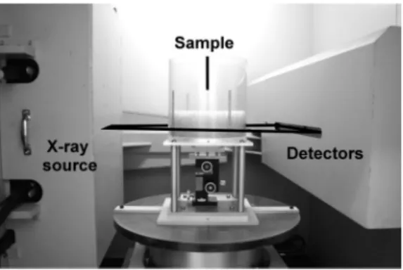
2 MATERIAL AND METHODS 2.1 Experimental apparatus
The trapdoor problem tests were conducted in an acryl cylindrical box of diameter, 240 mm (Fig. 1). In the centre of the bottom plate of the box, a trapdoor made of an aluminium alloy could be placed presenting different aspect ratio depending on the case studied: 40×40 mm (aspect ratio 1:1), 80×40 mm (aspect ratio 2:1) or 120×40 mm aspect ratio 3:1), and respectively called T1, T2and T3. The trapdoor is supported by a
steel support with 4 vertical rods that can slide verti-cally in the steel support. One (with T1and T2) or two
(with T3) load cells are placed between trapdoor and
Figure 1. Picture of test device place in X-Ray CT scanner.
the granular material on the trapdoor. The steel sup-port was vertically extendable so the trapdoor could be move downward with a screw. The displacement value of the trapdoor was controlled with a gauge. The different positions of the trapdoor corresponded to vertical displacement δ of, 0 mm, 0.1 mm, 1 mm, 2 mm, 5 mm, 10 mm and 20 mm.
2.2 Granular material
The granular material used in the tests was made of layers of single sized glass beads of, 80 mm height. Different samples were tested varying by the diame-ter of the beads: 2 mm, 4 mm and 6 mm respectively referred to as G2, G4and G6. The density of the beads
was of, γg= 2.52 g/cm3. The range of void ratio was
measured equal to, emin= 0.562 and emax= 0.661 and
the sample were tested with an initial void ratio cor-responding to the minimal value of, emin. The friction
angles of glass beads were measured on a G2sample
of minimal void ratio, by dry triaxial compression test with a 25 kPa confining pressure and found equal to,
ϕp= 30◦for the peak value and ϕc= 24◦for the
crit-ical value. The friction angles of G4and G6samples
were assumed to be the same as for G2.
2.3 X-Ray CT
An industrial X-ray CT scanning system (Otani 2000, Otani 2002) of the Kumamoto University, Japan was used in this test series. It is a non-destructive method to investigate the spatial distribution of the densities. In this process, the sample is crossed by a collimated x-ray beam in several directions by rotation and trans-lation of the specimen. The intensities of the x-ray beams are measured and computed after the pene-tration of the specimen and an image of the section of the specimen can be reconstructed. The image obtained gives the distribution of CT-values which is related to the densities in the specimen by the absorp-tion coefficient of the x-ray beam for the scanning point. The X-ray CT system used here was equipped with 300 kV x-ray tubes (TOSCANER – 23200 min TOSHIBA Corp., Kumamoto University, Japan).
Table 1. Cases studied.
Case number 1 2 3
Effect of beads size T1× G2 T1× G4 T1× G6
Effect of trapdoor size T1× G4 T2× G4 T3× G4
2.4 Cases studied
As presented before, 3 different trapdoors and 3 different granular samples were used in the tests, resulting in a total of 5 different test cases: a series of tests focusing on beads size using trapdoor T1,
a series of tests focusing on trapdoor shape using sam-ples of G4. The different test cases are summarized in
Table 1.
For each case, the measurement of the force and the CT scanning were conducted on separated tests. The tests for the force measurement were repeated 5 times. The test for CT scanning was conducted only once per case and for the trapdoor displacement δ of, 0 mm, 2 mm, 5 mm, 10 mm.
2.5 Method of analysis of CT results
Trapdoor tests were performed on sample containing glass beads and air voids. The CT images give a spatial distribution of CT value which depends on the value of the density in each pixel. It is necessary to deter-mine a threshold CT value in order to decide if one given pixel corresponds to a glass beads or to an air void. The threshold CT value was fixed based on the method explained by Chevalier & Otani (2011). With the threshold value, raw CT images were converted into binary images, where particles could be clearly identified. Then, mechanisms could be analyzed based on the comparison between images taken for differ-ent positions of trapdoor. More details about the data treatment can be found in Chevalier & Otani (2011).
3 EFFECT OF BEADS SIZE 3.1 Effect on load transfer
The stress on trapdoor was measured for several posi-tions of the trapdoors. In each case, the initial mean stress on the trapdoor, resulting from the weight of the initial height of glass beads, was of, 1.5 kPa approx-imately. The amplitude of the load transfer in the granular material was quantified by a stress ratio. The stress ratio is the ratio of the mean stress on trapdoor to the initial stress value.
The curve of stress ratio vs. displacement is shown on Fig. 2 for glass beads G2, G4and G6.The response
of the granular layer to the displacement of the trap-door broke down into 2 successive phases. First, as soon as the trapdoor is moved downward, a sudden important decrease of the stress was measured, as observed in other trapdoor studies (Chevalier & Otani
Figure 2. Stress ratio vs. trapdoor displacement for samples G2, G4and G6with trapdoor T1.
2011, Chevalier et al. 2012). The minimal value of the stress was obtained for a trapdoor displacement of, 2 mm. Second, from 2 mm to 20 mm displacement, the mean stress on trapdoor increased slightly, still remaining in much smaller values than initial stress.
It could be noticed that, the influence of glass beads size on the minimal stress was clearly identified: the minimal stress increased as glass beads size decreased. Minimal stress ratios were equal to 8% for G6, 14%
for G4and 16% for G2. Based on the results, it can
be assumed that the minimal stress ratio converge to a limit as glass beads size is small enough. For the increase phase, the different sample could not be classed as easily as for minimal stress ratio. The stress ratio were ordered very differently for 10 mm and 20 mm displacement, so that no clear effect of glass beads size could be observed.
3.2 Propagation of the disturbance
The displacement of the trapdoor at the bottom of the granular layer creates a disturbance in the material, in terms of kinematics. For small displacement of the trapdoor, a small part of the material located in the vicinity of the trapdoor is affected and moves. Then, as the trapdoor displacement increases, the volume of disturbed material increases. At some point, a subsi-dence at the free surface of the layer can eventually be observed. Based on the binary images obtained from CT scanning, the volume disturbed by the trapdoor displacement could be measured.
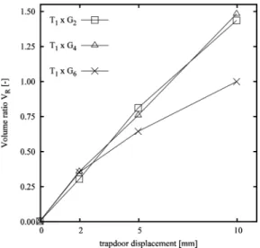
For a better understanding, the measured volume was divided by the volume of material located above the trapdoor to obtain a disturbed volume ratio VR
(Fig. 3). The Figure 4 shows the variation of the vol-ume ratio vs trapdoor displacement for glass beads G2,
G4and G6.
Figure 3. Definition of the volume ratio.
Figure 4. Volume ratio VR vs. trapdoor displacement for
samples G2, G4and G6with trapdoor T1.
It was observed that the disturbed volume ratio increased as the trapdoor was moved. The disturbance due to the displacement of the trapdoor progres-sively propagated inside the granular layer. Until a trapdoor displacement of, 2 mm, the disturbed volume ratio was very similar for the three sizes of glass beads. Then, for 5 and 10 mm displacement, a difference could be observed between 6 mm beads (G6) on one
side and 2 and 4 mm beads (G2, G4) on the other side.
For G6, the disturbed volume ratio was smaller,
sug-gesting that the propagation of the disturbance inside the granular material was more difficult. At the end of the test, VRis close to a value of, 1.0, which means
that the volume affected by the movement of the trap-door was equivalent to the volume above the traptrap-door. For G2and G4, the volume ratio at the end of test is
close to 1.5: the disturbance due to trapdoor movement propagated in the same way with both size of the glass beads.
3.3 Shape of the disturbance
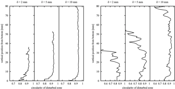
The shape of the horizontal cross section of the dis-turbed volume was measured with the circularity parameter C defined by
Figure 5. Circularity of disturbed volume in horizontal cross sections for G2(left) and G6(right).
where A is the area of the cross section and P its perimeter. C= 1 for a circular cross section and C =
π/4 for a square cross section (shape of trapdoor T1).
The circularity of the cross sections of disturbed vol-ume vs. vertical position z of the cross section are shown on Figure 5 for glass beads G2and G6for δ= 2,
5 and 10 mm.
First, it can be noticed that the disturbed volume propagated from the bottom to the free surface of the layer as the trapdoor displacement increased. The propagation was similar for both size G2 and G6.
Obviously, the circularity of disturbed volume was close to the value for square near the bottom of the test box.
For glass beads G2, as z increased, C tended to a
plateau value of 0.95, which is very close to the value for a circle. For glass beads G6, the variation of C vs.
z is less smooth than for G2, and the plateau value of
0.95 is reached for δ= 10 mm only.
The test results clearly showed that the failure planes bounding the disturbed volume of the granular mate-rial can make path among the grains in an easier way with finer grains. This observation has to be corre-lated with the influence of beads size on the load on the trapdoor, especially for small displacement of trapdoor.
4 EFFECT OF TRAPDOOR SHAPE 4.1 Effect of load transfer
The curves of the stress ratio vs. trapdoor displace-ment for the three cases of trapdoors are shown on Figure 6. A clear influence of trapdoor aspect ratio could be observed on the amplitude of the load transfer in granular layer.
Figure 6. Stress ratio vs. trapdoor displacement for trap-doors T1, T2and T3and with glass beads G4.
The stress ratio increased with the aspect ratio of the trapdoor, for any displacement of the trap-door: arching effect is more effective in terms of load transfer, if aspect ratio is small (close to the square in our case). It can be noticed that minimal stress ratios obtained with T1 (21%) and T2 (24%) were
very close. As before, the two successive ‘decrease-increase’ phases in the response of the granular layer could still be observed.
As the value of aspect ratio changes, the 3-dimensional configuration (low aspect ratio) changes to a 2-dimensional configuration of the trapdoor
problem (high aspect ratio). Because of the reduced number of values of aspect ratios used here, no clear transition between 3-dimensional and 2-dimensional conditions could be observed.
4.2 Propagation of the disturbance
From the CT images, binary images obtained for dif-ferent positions of the trapdoor were compared and a volume ratio VRcould be identified and measured
(Fig. 3). VR is the ratio of the volume of disturbed
zone to the volume of material located above trapdoor in the initial state. The curves showing the varia-tions of VRvs. trapdoor displacement δ are given on
Fig. 7.
The volume ratio obtained for the cases of trap-doors T1 and T2 were very close, suggesting a
sim-ilar propagation of the disturbance in the granular layer. On the other side, the volume ratio obtained for T3 was much higher. This result may suggest a
transition between 2-dimensional and 3-dimensional
Figure 7. Volume ratio vs. trapdoor displacement for trap-doors T1, T2and T3and with glass beads G4.
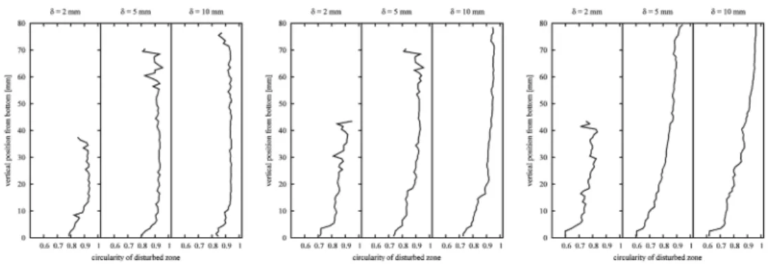
Figure 8. Circularity of disturbed volume in horizontal cross sections for T1(left), T2(middle) and T3(right), with glass
beads G4.
condition of trapdoor problem between T1and T2on
one side and T3on the other side. However, additional
aspect ratios should be tested in order to confirm this assumption.
4.3 Shape of the disturbance
Horizontal cross sections of disturbed volume were analyzed with the circularity parameter (Eq. 1). The variation of the circularity C from the bottom to the top of the granular layer is shown on Fig. 8 for trap-door T1 and T3. The circularity of square shaped
trapdoor T1 is equal to, π/4≈ 0.78 and equal to,
3π/16≈ 0.59 for T3.
For T1, a plateau value of circularity C= 0.95, was
reached for any value of trapdoor displacement δ and at a distance of, 5 to 10 mm from the bottom of the test box. On the contrary, for T3, the same plateau
value of circularity was reached for δ≥ 5 mm, and in the very upper part of the granular layer only. In both cases, the shape of horizontal cross section of disturbed zone changed from trapdoor shape (at the bottom of test box) to a circle shape at a distance large enough from the bottom of test box. As the aspect ratio increased, the distance necessary to observe a circle cross section increased, as well as the trapdoor displacement.
5 CONCLUSION
A parametric study of the trapdoor problem was con-ducted on particle size and trapdoor aspect ratio. The experimental tests included force measurement on the trapdoor and also CT scanning of the samples, for different positions of the trapdoor.
The results obtained showed that the amplitude of the load transfer resulting from arching effect depends on the size of the grains in the granular layer. When particles are fine enough compared to trap-door size, this effect vanishes. During traptrap-door test, the displacement of trapdoor induces a disturbance inside granular material. This disturbance propagates upward in the layer as trapdoor displacement increases.
As a result, a disturbed volume appears in the gran-ular material. The shape of the disturbed volume is influenced by grain size, especially for coarse grains and for small displacement of trapdoor. With coarse grains, the failure planes are more difficult to initi-ate. When trapdoor displacement are large enough, or particles fine enough, the shape of horizontal cross sections of the disturbed volume becomes close to a circle.
Aspect ratio of trapdoor is another important param-eter influencing arching effect. For a given aspect ratio, there is a transition in trapdoor problem between 3-dimensional conditions and 2-dimensional condi-tions. 3 values of aspect ratios were studied here varying from 1:1 to 3:1. The results didn’t make this transition appear clearly, even if similarities could be observed between aspect ratio 1:1 and 2:1, contrary to 3:1.
The amplitude of load transfer clearly decreases as aspect ratio increases. It was also observed that for trapdoor displacement large enough and at a distance from the trapdoor large enough, the shape of the dis-turbance propagating in the granular layer still tended to a circle shape.
The test results presented here involved a model granular material: samples of single sized glass beads. This material presented interesting properties for the observation in x-ray CT. It would be interesting to confirm the vanishing of size effect for finer par-ticles. Real geomaterials with higher friction angle could be used. In order to quantify the transition between 3-dimensional and 2-dimensional conditions of the test, other intermediate aspect ratio could be tested.
ACKNOWLEDGEMENT
This research was conducted with a Grant-in-Aid of the Japanese Society for the Promotion of Science (JSPS 20.08818).
REFERENCES
Chevalier, B.; Combe, G. & Villard, P. (2012), Experimen-tal and discrete element modeling studies of the trapdoor problem: Influence of the macro-mechanical frictional parameters, Acta Geotechnica, 7(1):15–39.
Chevalier, B. & Otani, J. (2011), Arching observation in three-dimensional trapdoor problem with X-ray CT and discrete element method, Soils and Foundations, 51(3):459–469. Dewoolkar, M. M.; Santichaianant, K. & Ko, H.-Y. (2007),
Centrifuge model of granular soil response over active circular trapdoors, Soils and Foundations, 45(5):931–945. Pardo, G. S. & Sáez, E. (2014), Experimental and numerical study of arching soil effect in coarse sand, Computers and
Geotechnics, 57:75–84.
Tanaka, T. & Sakai, T. (1993), Progressive failure and scale effect of trap-door problems with granular materials, Soils
and Foundations, 33(1):11–22.
Terzaghi, K. (1936), Stress distribution in dry and saturated sand above a yielding trap-door, in Proceedings of
Interna-tional Conference of Soil Mechanics, Harvard University,
Cambridge, pp. 307–311.
Vardoulakis, I.; Graf, B. & Gudehus, G. (1981), Trap-door problem with dry sand: a statical approach based upon model test kinematics, International Journal for
Numeri-cal and AnalytiNumeri-cal Methods in Geomechanics, 5:57–78.
Vardoulakis, I.; Vairaktaris, E. & Papamichos, E. (2004), Sub-sidence diffusion–convection: I. The direct problem,
Com-putational Methods In Applied Mechanical Engineering,