Assuring Safety in High-Speed Magnetically Levitated (Maglev) Systems: The Need for a System Safety Approach
by
Shuichiro Daniel Ota M.E., Aeronautics and Astronautics
University of Tokyo, 2000
SUBMITTED TO THE DEPARTMENT OF AERONAUTICS AND ASTRONAUTICS IN PARTIAL FULFILLMENT OF THE REQUIRMENTS FOR THE DEGREE OF
MASTER OF SCIENCE IN AERONAUTICS AND ASTRONAUTICS AT THE
MASSACHUSETTS INSTITUTE OF TECHNOLOGY JUNE 2008
© 2008 Shuichiro Daniel Ota. All rights reserved.
The author hereby grants to MIT permission to reproduce and to
distribute publicly paper and electronic copies of this thesis document in whole or in part in any medium now known or hereafter created.
Signature of Author:
Department of Aeronautics and Astronautics May 6, 2008
Certified by:
-Professor of
Nancy G. Leveson Aeronautics and Astronautics Thesis Supervisor Accepted by: MASSACHUSETTS INSTITUTE OF TECHNOLOGY
AUG 0 1 2008
LIBRARIES
(
I -Prof. David L. Darmofal
-i Associate Department Head Chair, Committee on Graduate StudentsMtCHIVES
A N
~~---Assuring Safety in High-Speed Magnetically Levitated (Maglev) Systems:
The Need for a System Safety Approach
by
Shuichiro Daniel Ota
Submitted to the Department of Aeronautics and Astronautics on May 6, 2008 in Partial Fulfillment of the
Requirements for the Degree of Master of Science in Aeronautics and Astronautics
ABSTRACT
Magnetic levitation is a railway technology that enables vehicles to be magnetically suspended above their tracks. Although this technology is still under development, magnetically levitated (maglev) systems have great potential to introduce significant changes in today's transportation networks.
This thesis proposes an approach to assuring safety in high-speed maglev systems. It examines characteristic features of the systems, and analyzes the Japanese commuter railway accident in 2005, using Systems Theory Accident Modeling and Processes (STAMP) and System Dynamics models. The characteristic features reveal that the likelihood and potential severity of accidents in maglev systems are higher than those in conventional railway systems because of their high speed, levitation technology, software intensiveness, and other factors. A primary lesson learned from the accident is the importance of risk/hazard analysis that can qualitatively focus on the severity of accidents and human factors. These findings are put together in the form of requirements of risk/hazard analysis and organizational structures. This thesis demonstrates that these requirements, which are not entirely consistent with current actual practices based on international railway standards, conform well to the fundamentals of System Safety, which is an organized and established method to assure safety in complex systems.
Thesis Supervisor: Nancy G. Leveson
Acknowledgements
I would like to express my gratitude to Professor Nancy Leveson, my thesis supervisor, for her guidance and patience toward the completion of this research. I am deeply grateful to the members of the Columbia Group, an informal multidisciplinary group of faculty and students at MIT, especially Professor Joseph Sussman and Professor John Carroll, who provided useful insights for this thesis.
I also thank my friends in Room 33-407 and my family, Ayako, Ryoichiro, and Keijiro, who have given me warm encouragement throughout my studying. Finally, I gratefully show appreciation to Central Japan Railway Company, my financial sponsor, for giving me a chance to study at MIT over two years.
Contents
1 Introduction 13
1.1 Motivations ... 13
1.2 Objectives and methodology ... 14
1.3 Thesis structure ... 15
2 Characteristic Features of Maglev Systems 17 2.1 Magnetically levitated (maglev) systems ... 17
2.1.1 Overview ... 17
2.1.2 Current maglev projects under consideration ... 18
2.2 Characterizing high-speed maglev systems ... 25
3 Current Approaches to Safety of High-Speed Maglev Systems 31 3.1 Overview of standards for conventional railway applications ... 31
3.1.1 Framework of international standards ... 31
3.1.2 IEC 62278 ... 33
3.1.3 MIL-STD-882D ... 41
3.1.4 Comparison between IEC 62278 and MIL-STD-882 ... .. 44
3.2 Current approaches to safety of maglev systems ... 45
3.2.1 German approach ... 45
3.2.2 Japanese approach ... ... 49
4 Lessons Learned from the Fukuchiyama Line Derailment 53 4.1 Reviews of a STAMP analysis and System Dynamics model ... 54
4.1.1 Investigating and analyzing accidents ... 54
4.1.2 Systems Theory Accident Modeling and Processes analysis ... 55
4.1.3 System Dynamics ... 59
4.2.1 4.2.2 4.2.3 4.2.4 4.2.5 4.2.6 4.2.7 4.2.8 4.2.9 4.2.10 4.3 Lessons
Proximate events on the Fukuchiyama Line ... System hazards, system safety constraints, and control structure .... Physical process view of the accident ... Operations ...
Rolling stock development ... Ground equipment development ... Timetable development ...
Board of Directors ... Ministry of Land, Infrastructure and Transport ... Modeling the dynamics of the Fukuchiyama Line derailment ... learned from the Fukuchiyama Line derailment ...
5 Hazard Analysis Requirements for High-Speed Maglev Systems
5.1 Appropriate hazard analysis for maglev systems ... 5.1.1 Hazard-related definitions ... 5.1.2 Overview of hazard analysis ... 5.1.3 Hazard analysis and risk assessment requirements for maglev
system s ...
5.2 System Safety and high-speed maglev systems ... 5.2.1 Overview of the System Safety approach ... ... 5.2.2 Applicability of System Safety approaches to maglev systems ... 6 Organizational requirements for high-speed maglev systems
6.1 Brief reviews of STAMP risk analysis ... 6.2 Risk analysis of high-speed maglev system organizations ... ...
6.2.1 STAMP risk analysis process outcomes ... 6.2.2 Requirements and recommendations from risk analysis ... 7 Conclusion 7.1 Summary ... 7.2 Future work ... References 63 66 68 69 72 74 78 81 82 83 87 97 97 97 101 103 112 112 117 119 119 121 121 132 137 137 139 141
List of Figures
1.1 Structure of this thesis ... 16
2.1 Comparison of railway operating speed ... 26
3.1 Structure of railway standards ... 33
3.2 Quality of service and railway RAMS ... 34
3.3 Inter-relation of railway RAMS elements ... 35
3.4 System life cycle ... 37
3.5 Procedures for performing hazard and safety/risk analysis ... 38
3.6 Procedures for performing RAM analysis excerpted ... 39
3.7 Example of a fault tree graphic ... 47
4.1 Classification of control flaws leading to hazards ... ... 57
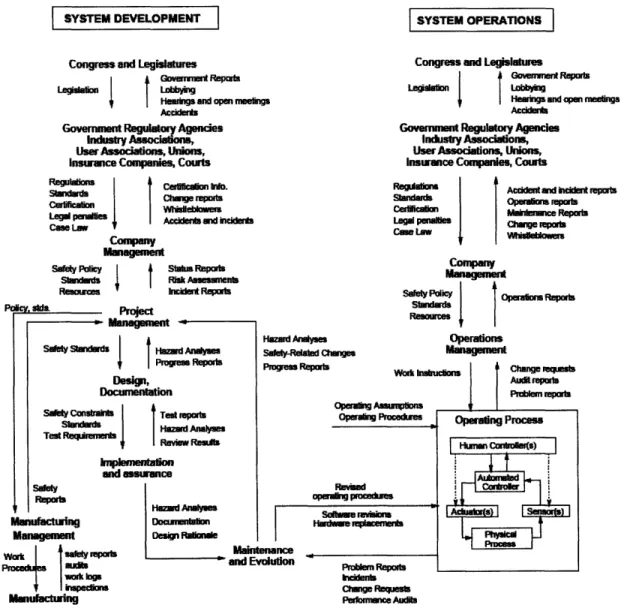
4.2 General form of a socio-technical control structure ... 58
4.3 Positive feedback loop structure ... 60
4.4 Negative feedback loop structure ... 60
4.5 Example of causal loop diagrams ... 61
4.6 Example of stocks and flows ... 61
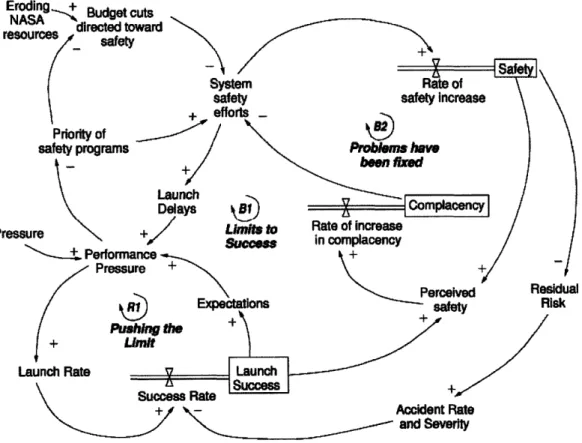
4.7 Simplified model of the dynamics behind the space shuttle Columbia loss ... 62
4.8 Driver's driving record on the day of the accident ... 63
4.9 Basic railway safety control structure ... ... 67
4.10 Physical components of the railway safety control structure ... 68
4.11 Physical and operational components of the railway safety control structure ... 69
4.12 Physical and rolling stock development components of the railway safety control structure ... 73
4.13 Physical and ground equipment development components of the railway safety control structure ... 75
4.14 Physical and timetable development components of the railway safety control
structure ... 78
4.15 Board of Directors component of the railway safety control structure ... 81
4.16 Ministry of Land, Infrastructure and Transport component of the railway safety control structure ... ... 82
4.17 System Dynamics model for the Fukuchiyama Line derailment ... 84
4.18 Variables in the model that affected the level of Risk Awareness by Company .. 84
4.19 Variables in the model that were effected by Risk Awareness by Company ... 86
4.20 Variables in the model that affected Driver's Attention ... 86
4.21 Variables in the model that affected the level of Risk of Overturning Accidents 87 4.22 Factors influencing railway RAMS ... 89
4.23 Modified System Dynamics model for the Fukuchiyama Line derailment ... 93
5.1 Com ponents of risk ... 99
5.2 Inductive and deductive analysis relationship ... 106
5.3 Examples that show contributions of the U.S. Air Force ... 116
6.1 Process of a STAMP risk analysis ... 120
6.2 Basic high-speed maglev system safety control structure ... 124
6.3 Comparison between the Japanese railway organizational structure and European railway organizational structure ... 123
List of Tables
2.1 Classification of current levitated railway system projects ... 19
2.2 Specifications of the Shanghai maglev line ... 21
2.3 History of the German Transrapid project ... 21
2.4 Proposed specifications of the Munich Transrapid project ... 22
2.5 History of the superconducting maglev project in Japan ... 24
2.6 Comparisons between German Transrapid project and Japanese superconducting maglev project ... 25
3.1 Frequency of occurrence of hazardous events ... 36
3.2 Hazard severity level ... 36
3.3 Qualitative risk categories ... 36
3.4 Typical example of risk evaluation and acceptance ... 36
3.5 Safety integrity levels ... ... 40
3.6 Minimum levels of independence of those carrying out functional safety assessment ... ... 41
3.7 Software control categories ... 43
3.8 Example of software hazard criticality matrix ... 43
3.9 Sample of the FMEA worksheet ... . ... 47
4.1 Questionnaire result about the overturning velocity ... 71
4.2 Functions that ATS system provides ... 74
4.3 Time-line regarding the introduction of ATS-P into the Fukuchiyama Line ... 77
4.4 Transitions of the timetable on the Fukuchiyama Line ... 79
4.5 Questionnaire results about the reasons of delay ... 80
4.6 Questionnaire results about the length of delay ... 80
5.1 Comparisons of risk-related analaysis terms in IEC 62278 and MIL-STD-882D ... 100
5.2 Major attributes of hazard analysis techniques ... ... 102
5.3 Advantages and disadvantages of qualitative and quantitative approaches ... 104
5.4 Inductive and deductive analysis characteristics ... 106 5.5 Comparison between lessons learned from the Fukuchiyama Line derailment
Chapter 1
Introduction
1.1
Motivations
Magnetic levitation is a railway technology that enables vehicles to be magnetically suspended above their tracks. The technology is in use in several places; however, it should be considered still under development. Further research and development are required in order to realize this next generation transportation system.
Magnetically levitated (maglev) systems have great potential to introduce significant changes in today's transportation networks. First of all, one of the significant characteristics of the maglev system is its speed. The absence of contact between the vehicles and ground allows the vehicles to run at an extremely high speed, about 500 kilometers per hour in the case of Japanese maglev systems, which is twice as fast as that of conventional high-speed trains. It is expected that more people would choose to take railways using maglev systems than airplanes. The next advantage is that maglev systems are environmentally friendly. They produce fewer carbon dioxide (CO2) emissions than airplanes (Railway Technology Research Institute [RTRI], 2006; Transrapid International, 2006). This characteristic is suited to recent concerns about global warming.
On the other hand, high-speed operation, levitation technology, software intensiveness, structural fragility, and other characteristic features will increase the likelihood and potential severity of an accident in high-speed maglev systems, compared to those in conventional railway systems. Therefore, closer attention should be paid to assuring safety in high-speed maglev systems.
1.2
Objectives and methodology
The purpose of this thesis is to propose an appropriate approach to assuring safety in high-speed maglev systems. It is important to note that the scope of this thesis is high-high-speed maglev systems. While there exist various types of proposed maglev systems, some of which are appropriate for high-speed railways, and others for local networks, the most notable high-speed maglev projects are: (1) the German Transrapid project and (2) the Japanese superconducting maglev project. These two projects comprise the scope of this thesis.
In light of the primary purpose, this thesis will follow three steps. First, current approaches to safety of high-speed maglev systems are examined. In addition to actual approaches in the German and Japanese high-speed maglev system projects, existing international standards for conventional railway applications, mainly IEC 62278: Railway
applications - Specifications and demonstration of reliabiliy, availability, maintainability, and safety (RAMS), are reviewed. The German maglev systems are based on the standards for
conventional railway applications (Steriner & Steinert, 2006).
Next, the Japanese commuter railway accident in 2005 is analyzed using Systems Theory Accident Modeling and Processes (STAMP) and System Dynamics models. Although this accident had nothing to do with maglev systems, looking at this accident is worthwhile for high-speed maglev systems. This accident was caused by a representative company of the railway industry in Japan, which is an advanced country in the field of railway. It is supposed that this kind of sophisticated company in terms of railway technology would operate a maglev train in the future. A STAMP analysis has been developed by Nancy Leveson at Massachusetts Institute of Technology (MIT) to investigate today's complex accidents. System Dynamics was originally developed by Jay Forrester at MIT in the 1950's for mangaers and public policy makers to use to design and implement high-level policies. Leveson (2002) has proposed that safety issues be analyzed using a combination of STAMP and System Dynamics. This thesis adopts its proposal.
Finally, an appropriate approach to assuring safety in high-speed maglev systems is derived from the characteristic features of high-speed maglev systems, current actual approaches, and lessons learned from the accident.
1.3 Thesis structure
Following this Introduction in Chapter 1, maglev systems are introduced in Chapter 2. First, the concept's origins and history and the current status of maglev projects, all over the world, are reviewed. Next, maglev systems are characterized for the following analysis.
In Chapter 3, current approaches to safety of high-speed maglev systems are examined. It consists of two parts: (1) Overview of existing international standards for conventional railway applications and (2) Review of current actual approaches to safety of high-speed
maglev systems in Germany and Japan.
The Fukuchiyama Line derailment accident, which occurred in Japan on April 25, 2005, is analyzed in Chapter 4. After a brief review of a STAMP analysis and System Dynamics model, first the proximate events, then the STAMP analysis and System Dynamics model of this accident are presented, followed by lessons learned. Derived here is an important lesson that risk/hazard analysis is the key to assuring safety.
Subsequently, in Chapter 5, the findings through characterizing high-speed maglev systems and analyzing the Fukuchiyama Line derailment accident are put together in the form of requirements of risk/hazard analysis. It is demonstrated that these requirements are not entirely consistent with current actual practices based on international railway standards but conform well to the fundamentals of System Safety, which is an organized and established method to assure safety in complex systems.
In Chapter 6, organizational risk analysis is conducted for high-speed maglev systems. This chapter derives the organizational requirements to avoid poor risk analysis, which is
considered to be the most critical hazard in high-speed maglev systems, applying a STAMP risk analysis.
Finally, Chapter 7 concludes this thesis. Figure 1.1 shows the thesis structure.
Chapter 1 Introduction Chapter 2 Maglev Systems * Technology Overview * Current Projects * German type * Japanese type * Characteristic Features Chapter 3 Current Approaches * International Standards * IEC 62278 * MIL-STD-882D * Actual Approaches * Germany * Japan Chapter 4 Fukuchiyama Line Derailment Analysis * STAMP model * System Dynamics model * Lessons Learned
Chapter 6
Organizational Structure Requirements
* STAMP Risk Analysis
* Findings and Recommenndations
Chapter 7
Conclusion
Figure 1.1: Structure of this thesis. Chapter 5
Hazard Analysis Requirements
* Appropriate Hazard Analysis * Comparison with Current
Approaches
* Comparison with System Safety Approaches ,,. .# w | ·C I
I1
CChapter 2
Characteristic Features of Maglev
Systems
In this chapter, magnetically levitated (maglev) systems are introduced. First, the concept's origins and history, and the current status of maglev projects all over the world are reviewed.
Subsequently, maglev systems are characterized for the following analysis.
2.1
Magnetically levitated (maglev) systems
2.1.1 Overview
Magnetic levitation is a railway technology that enables vehicles to be magnetically suspended above their tracks. Since the magnetically levitated (maglev) vehicles travel free of friction, it is possible to increase operating speeds without a terrific noise. The technology is in use in several places; however, it should be considered still under development. Further research and development are required in order to realize this next generation transportation system.
There are primarily two types of levitation technology: electrodynamic suspension (EDS) and electromagnetic suspension (EMS). EDS, commonly known as "repulsive levitation," uses a repulsive force between the vehicle's magnetic field and the track's magnetic field. (In EDS, both vehicles and tracks are required to generate magnetic fields.) EMS, commonly known as "attractive levitation," uses an attractive magnetic force between a steel track and electromagnets attached to vehicles. Details will be described in the following subsection.
The concept of maglev systems is not new. It was 1914 when Emilie Bachelet, a French-born American engineer, exhibited a model of maglev systems using EDS technology in London. Hermann Kemper of Germany subsequently pioneered the concept of an electromagnetically levitated train system (EMS) in 1936.
Maglev systems have the potential to introduce great changes in today's transportation networks. First of all, one of the significant characteristics of the maglev system is its speed. The absence of contact between the vehicles and ground allows the vehicles to run at an extremely high speed, about 500 kilometers per hour in the case of Japanese maglev systems, which is twice as high as that of conventional high-speed trains. It is expected that more people would choose to take railways using maglev systems than airplanes. The next advantage is that maglev systems are environmentally friendly: They produce fewer carbon dioxide (CO2) emissions than airplanes while offering high-speed performance (RTRI, 2006; Transrapid International, 2006). This characteristic is suited to recent concerns about global warming.
2.1.2 Current maglev projects under consideration
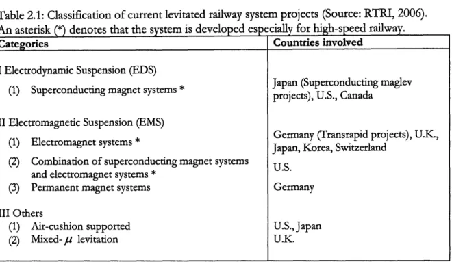
There exist various types of levitated railway systems under consideration all over the world, in terms of suspension methods and the types of magnets applied, as shown in Table 2.1. Some of these systems are appropriate for high-speed railways, and others for local networks. Among high-speed maglev systems, the most notable projects are: (1) the German Transrapid project and (2) the Japanese superconducting maglev project. The former uses electromagnetic suspension (EMS) while the latter uses electrodynamic suspension (EDS). Both are intended for high-speed railway systems and comprise all of the scope of this thesis as mentioned in the previous chapter. A brief overview of the two is given below, and Table
Table 2.1: Classification of current levitated railway system projects (Source: RTRI, 2006). An asterisk (*) denotes that the system is developed especially for high-speed railway.
Categories
I Electrodynamic Suspension (EDS) (1) Superconducting magnet systems * II Electromagnetic Suspension (EMS)
(1) Electromagnet systems *
(2) Combination of superconducting magnet systems and electromagnet systems *
(3) Permanent magnet systems III Others
(1) Air-cushion supported (2) Mixed- p levitation
Countries involved
Japan (Superconducting maglev projects), U.S., Canada
Germany (Transrapid projects), U.K., Japan, Korea, Switzerland
U.S. Germany
U.S., Japan U.K.
German Transrapid Project
The German high-speed maglev system named Transrapid is one of the most advanced levitated railway systems being proposed anywhere in the world and is representative of electromagnetic suspension (EMS) for high-speed transportation (RTRI, 2006). The system is being developed by German companies, namely Siemens, ThyssenKrupp, and Transrapid International, which was established by Siemens and ThyssenKrupp as a joint company for systems integration, marketing, and maintenance support. According to Transrapid International (2006), Transrapid is suitable both as a fast link between a city center and its outlying airport, as a fast connection between city pairs, and as a long-distance transportation system.
Technology: In order to achieve suspension, Transrapid uses an attractive magnetic force
between electronically controlled electromagnets (called support magnets) in the vehicles and ferromagnetic rails installed on the underside of the T-shape (monorail type) guideway. The gap between the vehicles and guideways is electronically controlled to be about 10 millimeters.
As for the propulsion system, the synchronous long-stator linear motor is adopted. A linear motor is essentially an electric motor that has its stator "unrolled" so that instead of producing a torque, it produces a linear force along its length. In the case of Transrapid,
rotors correspond to the support magnets attached to the vehicles, while stators correspond to the ground coils. (Rotors and stators are basic components of conventional motors.) By continuously supplying alternating current to the ground coils, an electromagnetic traveling field is generated, which moves the vehicles, pulled along by their support magnets. The maximum operational speed is 500 kilometers per hour.
History: Electromagnetic suspension systems have a long history, and it was 1922 when the concept was first proposed (RTRI, 2006). After significant advances by Hermann Kemper, the first passenger-carrying prototype vehicle was demonstrated in Munich, Germany in 1971. The construction of the guideway of the Transrapid Test Facility (TVE) began in 1980, and intensive running tests have been conducted since then. The TVE, which was completed in 1987, has a total length of 31.5 kilometers and is the world's longest test facility for maglev systems. New prototype vehicles were continuously introduced in the test facility. The latest versions are the pre-production prototype vehicle Transrapid 08 (TR08), which was delivered in 1999, and the TR09 in 2007, which is a prototype vehicle especially for the Munich Transrapid line and is slightly different from the TR08 (Tum, Huhn, & Harbeke, 2006).
In the spring of 2004, Shanghai Maglev Transportation Development Co. Ltd. (SMTDC) began the world's first commercial Transrapid in Shanghai, China, with the technical support of the German consortium that consisted of Siemens, ThyssenKrupp, and Transrapid International. This is the first and sole commercial high-speed maglev line. The line, which connects Pudong International Airport and Long Yang Road Station, is 30 kilometers long, and the maximum operating speed is 430 kilometers per hour, which is higher than any other rail system in every day normal service (Transrapid International, 2004). The specifications are shown in Table 2.2.
On September 22, 2006, the Transrapid vehicle, the TR08, collided with a maintenance vehicle at a speed of about 170 kilometers per hour at the TVE test track. Twenty-three people were killed and ten were injured in this accident. This was the first accident that
caused fatalities on any maglev systems.
Table 2.2: Specifications of the Shanghai maglev line (Source: Transrapid International, 2004). Length of the route 30km, double track Link to the Service Center 3km, single track
Stations Long Yang Road, Pudong International
Airport
Number of Vehicles 3 vehicles, each with 5 sections
Running Speed 430km/h
Traveling Time 8 minutes
Service Frequency Every 10 minutes
Table 2.3: History of the German Transrapid project.
1936 Hermann Kemper in Germany pioneered the concept of an electromagnetically levitated railway system
1971 Presentation of the first passenger-carrying prototype vehicle in Munich, Germany 1980 The construction of the guideway of the Transrapid Test Facility (TVE) began. (It
was finally completed in 1987.)
1984 Introduction of two-section test vehicle, Transrapid 06, designed for a speed of 400 km/h
1988 Introduction of two-section test vehicle, Transrapid 07, designed for a speed of 500 km/h
1998 Formation of a joint company, Transrapid International, and subsequently
Transrapid International-USA, whose mission is to promote Transrapid in the U.S. 1999 Introduction of pre-production prototype vehicle, Transrapid 08 (TR08)
2004 The Shanghai Transrapid line began the first commercial operation in Shanghai, China.
2006 TR08 crashed into the maintenance vehicle, killing 23 people.
Future Plans: According to Transrapid International (2007), the Munich project, which
links Munich "Franz-Joseph Strauss" airport with the central station by Transrapid, is
currently under active consideration. The plan is to begin operation "in just a few years" as of publishing time. The project data is shown in Table 2.4, and it is important to note that this project as well as the existing Transrapid line in Shanghai, China is a short-distance application as airport shuttle, whose route is about 38 kilometers long. At the present time, there is no notable project of a fast urban link on medium and long-distance routes.
Table 2.4: Proposed specifications of the Munich Transrapid project (Source: Transrapid International, 2007).
Number of Vehicles 5
Sections per Vehicle 3
Seats 148
Number of Stations 2
Maximum Operating Speed 350 km/h
Travel Time 10 minutes
Service Frequency Every 10 minutes
Route Length Approx. 38 km
Japanese Superconducting Maglve Project
The high-speed maglev system in Japan is generally called "superconducting maglev," named after its key technology, superconductivity. This is a representative system of electrodynamic suspension (EDS). The final goal of the superconducting maglev project, which is primarily developed by Central Japan Railway Company (RC), is to establish a line between Tokyo and Osaka and to replace the Tokaido Shinkansen, a high-speed bullet train between them, which is operated by JRC, with the maglev vehicles (Central Japan Railway Company [JRC], 2007b).
Technology: There are some differences between the German Transrapid system and
Japanese superconducting maglev system in terms of technology besides suspension method (EMS and EDS). One of the most notable differences is that the Japanese superconducting maglev vehicles are equipped with superconducting magnets while the Transrapid vehicles carry conventional electromagnets. Superconductivity is the characteristic of some substances at very low temperatures to let electricity flow with no resistance. When an electrical current is applied to a coil in a superconducting state, this current continues to flow permanently, resulting in the creation of a very large magnetic field. The vehicles are equipped with the superconducting magnets, which generate the necessary magnetic field. When the vehicles pass at a high speed, an electric current occurs through the coils installed in the guideways, generating a magnetic force that pushes up the vehicles. The gap between the vehicle and the guideway is about 100 millimeters. (The guideway is horseshoe type, and the superconducting magnets are attached to both sides of the vehicles.)
As for vehicle propulsion, the superconducting maglev system also utilizes the concept of the synchronous long-stator linear motor, and there is no substantial difference between the two.
History: American engineers James Powell and Gordon Danby (1966) at Brookhaven
National Laboratory published the basic concept of the maglev system utilizing supeconducting magnets in 1966. Japan National Railway (NR), which had begun the research on the maglev system in 1962, paid much attention to the Danby-Powell maglev systems and decided to adopt it at the end. Since then, JNR constructed the test track in Miyazaki, Japan in 1977 and carried out fundamental tests on the basic performance of the maglev system. Successively, in order to do advanced research, it was decided to construct a new test line, the Yamanashi Maglev Test Line in 1989. The Yamanashi Maglev Test Line is a 18.4 kilometer-long double track with tunnels, gradients, and curves, located in Yamanashi prefecture. Running tests on the Yamanashi Maglev Test Line commenced in 1997, and since then, Central Japan Railway Company (RC) has taken the lead in the research and development of the superconducting maglev system.
The trial runs of the maglev system on the Yamanashi Maglev Test Line have been progressing smoothly since April 1997. Running tests include a new record of the maximum speed of 581 kilometers per hour in December 2003, and a continuous running test in which the vehicles traveled 2,876 kilometers in one day in November 2003. In 2005, the Maglev Technological Practicality Evaluation Committee under the Japanese Ministry of Land, Infrastructure and Transport acknowledged that all the technologies necessary for the future revenue service were established, which is considered to be the ministry's endorsement that the superconducting maglev running test has achieved the technological criteria for practical application. As of September 2006, approximately 129,800 visitors, including Japanese Crown Prince, participated in test rides, and the total distance covered in running tests has been more than 530,000 kilometers (RTRI, 2006).
Table 2.5: History of the superconducting maglev project in Japan
1962 Japan National Railway (JNR) began research on maglev systems
1966 Powell and Danby published the concept of the superconducting maglev systems
1977 Test runs began on the Miyazaki Line
1987 JNR was divided into seven private companies including Central Japan Railway Company (JRC) and one institute, namely Railway Technology Research Institute
(RTRI). JRC and RTRI took over the maglev project from JNR.
1997 Test runs began on the Yamanashi Line. The maximum design speed of 550 km/h was achieved.
2003 Manned world speed record of 581 km/h was achieved.
2005 The Maglev Technological Practicality Evaluation Committee of the Ministry of Land, Infrastructure and Transport acknowledged that its foundation technology was sufficiently established for practical application.
2006 The cumulative travel distance exceeded 500,000km.
2007 JRC decided to introduce, on its own initiative, the superconducting maglev line between Tokyo and Nagoya in 2025, bearing all the cost for the project.
Future Plans: In April 2007, Central Japan Railway Company (JRC) formally, through
the financial report, acknowledged that they were considering beginning commercial operation of the superconducting maglev between the Tokyo metropolitan and Chukyo (or Nagoya) regions by 2025 (JRC, 2007a). JRC is a company that has been operating the Tokaido Shinkansen, a high-speed bullet train, which connects the Tokyo, Nagoya, and Osaka regions, for more than forty years. Since the performance of the Tokaido Shinkansen is at almost full capacity, the company is thinking of introducing, on its own initiative, the superconducting maglev line as a second, more advanced transportation artery that can replace the function of the Tokaido Shinkansen (RC, 2007b).
Subsequently, in December 2007, the company announced that the company decided to bear all the cost for this project. The estimated cost was JPY 5.1 trillion for construction costs and rolling stock expenses for approximately the 290 kilometer line of the superconducting maglev system. (RC, 2007c)
Table 2.6: Comparisons between German Transrapid project and Japanese superconducting maglev
project
German Transrapid project Japanese superconducting maglev project
Levitation Technology Electromagnetic suspension Electrodynamic suspension (EMS, attractive force) (EDS, repulsive force)
Gap between Vehicles and 10mm 100mm
Ground
Propulsion Technology Synchronous Linear Motor Synchronous Linear Motor Magnets in Vehicles Electromagnets Superconducting Magnets
Guideway T-Shape Horseshoe Shape
2.2
Characterizing high-speed maglev Systems
Following are safety-related significant characteristics of high-speed maglev systems. Some characteristics are described in the previous sections; however, they are re-stated from the viewpoint of safety.
High-speed operation
One of the most notable characteristics of high-speed maglev systems is the high-speed operation. For example, the operating speed of the Japanese superconducting maglev is 500 kilometers per hour, which is twice as high as that of conventional high-speed trains. Furthermore, it has a potential to increase its operating speed; on December 2, 2003, the Japanese superconducting maglev vehicles reached the maximum speed of 581 kilometers per hour, which was a Guinness world record of manned vehicles. The maximum speed of the German Transrapid, as well as the Japanese superconducting maglev, is designed to be
I
I';Lls
Operating Speed 430km/h 500km/h
Existing Line Shanghai Maglev Line None
Next Proposed Project Munich Project ("in a few Tokyo-Nagoya Project
years') (in 2025)
500 kilometer per hour, while the Shanghai maglev line is operated at a speed of 430
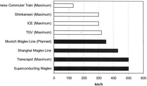
kilometer per hour. Figure 2.1 compares the operating speeds of some representative railway systems.
Japanese Commuter Train (Maximum) Shinkansen (Maximum) ICE (Maximum) TGV (Maximum) Munich Maglev Line (Planned) Shanghai Maglev Line Transrapid (Maximum) Superconducting Maglev
0 100 200 300 400 500 600
kmlh
Figure 2.1: Comparison of railway operating speed: Shinkansen, ICE, and TGV are conventional high-speed railway systems in Japan, Germany, and French, respectively. ("Maximum" in parentheses means some of their network lines, not all of them, are operated at that speed.)
This feature, the high-speed operation, affects safety of maglev systems in two ways. First, when the operating speed is increased, delays in processing become unacceptable. Suppose that there are anomalies in guideways ahead. It is required to spontaneously deal with this situation, since the vehicles would reach the point in a short time. At the same time, increasing the operating speed leads to an increase in an inertia force; the vehicles cannot promptly stop or change the track, and there are few options during the high-speed operation with respect to movement. To sum up, the high-speed operation makes the system
much more potentially dangerous.
Next, the high-speed operation increases the potential accident severity in maglev systems. Suppose that the vehicles accidentally crash into an obstacle. When the collision speed is not so high, it may result in minor damage. However, there is a possibility that the vehicles crash at a speed of 500 kilometers per hour. In that case, damage could be enormous. In the Fukuchiyama Line derailment accident in 2005 in Japan, which will be analyzed in Chapter 4, the conventional train vehicles crashed into an apartment at a speed of about 100 kilometers
OWI I , - , I - r I I
per hour, which is considered to be rather low compared to the high-speed operation of the maglev vehicles. Even so, the first two cars were completely damaged, no less than 106 passengers, in addition to the driver, were killed, and 562 others were injured. In short, the high-speed operation could result in the larger number of fatalities and injuries in case of an accident.
Levitation
Another characteristic to be mentioned here is, by definition, that the vehicles are levitated. As described before, the superconducting maglev vehicles are levitated about 100 millimeters above their tracks, and the gap between the Transrapid vehicles and tracks is controlled to be 10 millimeters, as shown in Table 2.6.
This condition, in which the vehicles are levitated, adds new hazards as well as new types of accident causes. When the mechanism for levitation does not work well, the vehicles inevitably crash into the tracks, which may result in substantial damage. This is recognized as a major hazard, which is unique to the maglev systems. In order to mitigate this hazard, the Transrapid vehicles and the superconducting maglev vehicles are equipped with skids (1ransrapid International, 2006) and sets of wheels (RTRI, 2006), respectively, for emergency landing. However, in any event, falling is unavoidable, which leads to an accident.
Structural fragility
Making the vehicles light is extremely important for maglev vehicles (Sterinert & Keller, 2004; RTRI, 2006), since it requires much energy consumption to levitate heavy vehicles (Transrapid International, 2006). In order to reduce weight, various measures are applied. One of these measures is to apply aluminum alloys to the vehicles extensively. The high-speed maglev vehicles as well as conventional railway vehicles adopt aluminum carriage bodies, which consist of aluminum longitudinal extrusions and aluminum side and end panels. Furthermore, aluminum undercarriages are introduced in the high-speed maglev vehicles (Steinert & Keller, 2004; RTRI, 2006), while conventional railway undercarriages are made of steel. (Both the German Transrapid and the Japanese maglev vehicles adopt aluminum undercarriages.) These measures successfully reduce the weight of the vehicles:
The Transrapid vehicle achieves 0.5 ton per seat (Transrapid International, 2006), while ICE 3 results in about 1.0 ton per seat (Siemens, 2002). Skllingberg and Green (2007) state:
While it is not clear at present what the upper limits of this advanced rail technology [the high-speed maglev systems] will be, it is obvious that both sheet and extruded aluminum and their fabrication technologies are vital to achieve these advances in transportation and infrastructure development.
Aluminum materials have superiority in many other aspects, such as high recycling efficiency and energy savings. The application of aluminum for rolling stock including the high-speed maglev vehicles will continue to grow in the future (Sakai, 2007).
It is fair, however, to say that the lightweight vehicles are structurally more fragile than conventional railway vehicles. This means that damages to the maglev vehicles would be greater in case of crashes. In the Transrapid accident in 2006 mentioned before, the first carriage of the TR08 was completely destroyed. One of the factors that magnified the damage is attributed to their lightweight vehicles. To sum up, lightweight vehicles increase the potential accident severity in maglev systems.
Mass transportation
High-speed maglev systems are designed to provide mass transportation railway service. The passenger capacities of the Shanghai maglev and of the Munich maglev are about 400 persons (Tum, Hugn, & Harbeke, 2006), which are in the same range as those of today's long-range wide-body airliners such as Boeing 777 and Airbus 340. There is no information available with respect to the capacity of the Japanese superconducting maglev at the time of this writing. However, the Japanese maglev system is designed to be a substitute for the Tokaido Shinkansen, whose capacity is more than 1,300 persons. It is apparent that the Japanese superconducting maglev, as well as the German Transrapid, becomes a mass
transportation system.
Long-connected vehicles are advantageous in the sense that there is a possibility that trouble in the first car, such as derailment and collision, does not spread to subsequent cabins of the train. Even so, it should be recognized that the larger number of people being transported could increase the number of fatalities and injuries in case of an accident.
Software intensiveness
The final characteristic feature is their software intensiveness. The Japanese superconducting maglev is a fully automatic system; there is no driver in the vehicles. To begin the operation, a running plan is provided for the traffic control system (TCS), which automatically gives instructions to the power conversion station and the safeguard system. Also, the system can automatically bring the vehicles to a halt when an anomaly is detected. Therefore, during normal operations, there is almost no room where human operators can work. Besides the automatic operation, the superconducting maglev vehicles utilize various kinds of software systems, instead of hardware systems (RTRI, 2006). The German Transrapid, the TR09, is also driverless (Steriner & Steinert, 2006). Incorporating software in the systems is the recent trend of not only maglev systems but also the entire railway industry. Although there is no reliable way to measure the degree of the software intensiveness, it is apparent that the high-speed maglev systems will require more extensive use of software than conventional railway systems.
Leveson (1995) claims that software programs lead to a complex and tightly coupled designs, and Perrow (1999) agrees with her on that point. Leveson states:
If we accept Perrow's argument that interactive complexity and coupling are a cause of serious accidents, then the introduction of computers to control dangerous systems may increase risk unless great care is taken to minimize complexity and coupling.
It is fair to say that the various kinds of software programs that are incorporated into the maglev systems make the systems more complex and more tightly coupled, which could lead to an accident. For details, see Leveson (1995).
Conclusions
Two findings are: (1) The potential likelihood of an accident in high-speed maglev systems is higher than those in conventional railway systems, because of high-speed operation, levitation technology, and software intensiveness; and (2) The potential severity of catastrophic potential in high-speed maglev systems is also higher than those in conventional railway systems, because of high-speed operation, mass transportation, and structural fragility.
Consequently, these characteristic features demonstrate the need for more attention to be paid to safety in the high-speed maglev systems.
Chapter 3
Current Approaches to Safety of
High-Speed Maglev Systems
Current approaches to safety of high-speed maglev systems are examined in this chapter. It consists of two parts: (1) Overview of existing international standards for conventional railway applications and (2) Review of current actual approaches to safety of high-speed maglev systems in Germany and Japan. German maglev systems are considered to be based on the standards for conventional railway applications (Steiner & Steinert, 2006). Therefore, looking at current standards first is worthwhile although they are not necessarily intended for high-speed maglev systems.
3.1 Overview of standards for conventional railway applications
3.1.1
Framework of international standards
Three international standards have been defined for conventional railway applications (especially safety-related electronic systems) in the past few years.
* IEC 62278: Railway applications - Specifications and demonstration of reliability,
availability, maintainability and safety (RAMS)
* IEC 62279: Railway applications - Communications, signalling and processing systems
-Software for railway control protection systems
* IEC 62280: Railway applications - Communication, signalling and processing systems
While there is a generic standard for the safety of electronic safety-related systems, IEC 61508: Functional safety of electrical/electronic/programmable electronic safety-related systems, the three
standards above are regarded as application sector standards and as the sector specific interpretation of IEC 61508.
It is important to note that these standards were originally developed from European standards, namely the European Committee for Electrotechnical Standardisation (CENELEC), and every international standard above has its origin in the CENELEC standards. For example, IEC 62278 is derived from EN 50126, which has the same title,
Railway Applications - The Specification and Demonstration of Dependability, Reliability, Availability,
Maintainability and Safety (RAMS). (EN stands for the European Norms.) IEC 62279 and IEC
62280 are based on EN 50128: Railway applications - Communication, signalling and processing systems - Software for railway control and protection systems and EN 50159: Railway Applications
-Communication, signalling and processing systems - Safety-related communication in open/closed transmission systems, respectively. In European standards, there is another important standard
EN 50129: Railway applications - Safety-related electronicsystems for signalling, which has not
published as the international standard yet.
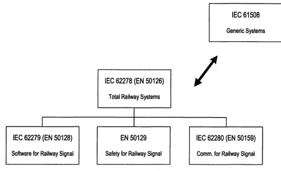
Among these standards, IEC 62278, or EN 50126, is the top-level document that covers the overall process for the total railway systems, and its idea is based on RAMS (Reliability, Availability, Maintainability, and Safety) methods. The remaining standards are primarily developed for a complete railway signalling system. The structure of the railway standards is summarized in Figure 3.1. Since the scope of this thesis is the total railway system, IEC 62278 is worthy of review and will be described further in the next subsection.
IEC 61508
Generic Systems
IEC 62278 (EN 50126)
Total Railway Systems
IEC 62279 (EN 50128) EN 50129 IEC 62280 (EN 50159)
Software for Railway Signal Safety for Railway Signal Comm. for Railway Signal
Figure 3.1: Structure of railway standards.
3.1.2 IEC 62278
In its introduction, IEC 62278 describes its purpose as follows: (The definition of Railway Authority is a body with the overall accountability to a Regulator for operating a railway system.)
This International Standard provides Railway Authorities and railway support industry with a process which will enable the implementation of a consistent approach to the management of reliability, availability, maintainability and safety, denoted by the acronym RAMS. Processes for the specification and demonstration of RAMS requirements are the cornerstones of this standard. This standard aims to promote a common understanding and approach to the management of RAMS.
Here, the important aspect is that IEC 62278 does not define targets, quantities, requirements or solutions for specific railway applications; its focus is on how to approach RAMS management, rather than what are RAMS requirements.
(a) The standard defines RAMS in terms of reliability, availability, maintainability and safety and their interaction.
It proposes that Railway Authorities manage the RAMS elements of reliability, availability, maintainability, and safety. In addition, the standard claims, as shown in Figure 3.2, that quality of service is achieved by RAMS elements and other attributes such as frequency of service and fare structure.
Quality of Service
Other attributes Railway RAMS
Figure 3.2: Quality of service and railway RAMS (Source: IEC 62278).
The definitions of RAMS elements in the standard are:
- reliability: probability that an item can perform a required function under given
conditions for a given time interval (t, t2) ;
- availability: availability of a product to be in a state to perform a required function
under given conditions at a given instant of time or over a given time interval assuming that the required external resources are provided;
- maintainability: probability that a given active maintenance action, for an item under
given conditions of use can be carried out within a stated time interval when the maintenance is performed under stated conditions and using stated procedures and resources;
- safety: freedom from unacceptable risk of harm.
The inter-linking of railway RAMS elements is shown in Figure 3.3. As shown here, it considers safety and availability to be the most critical parts to achieve a dependable system.
Railway RAMS
Safety Availability
Reliability and Operation and
maintainability maintenance
Figure 3.3: Inter-relation of railway RAMS elements (Source: IEC 62278).
(b) The standard introduces the concept of risk, and demands that risk analysis shall be performed at various phases of the system life cycle.
The definition of risk presented in the standard is probable rate of occurrence of a hazard causing harm and the degree of severity of the harm, and the concept of risk is the combination of two elements:
- the probability of occurrence of an event or combination of events leading to a hazard,
or the frequency of such occurrences;
- the consequence of the hazard.
Based on these ideas, IEC 62278 provides typical categories of probability or frequency of occurrence of a hazardous event, as shown in Table 3.1, and typical hazard severity levels, as shown in Table 3.2, in qualitative terms. Defining qualitative categories of risk and the actions to be applied against each category as in Table 3.3, it proposes the formation of a "frequency- consequence" matrix for evaluation of the results of risk analysis. An example of risk evaluation and risk reduction/controls for risk acceptance is demonstrated in Table 3.4.
Table 3.1: Frequency of occurrence of hazardous events (Source: IEC 62278).
Category Description
Frequent Likely to occur frequently. The hazard will be continually experienced. Probable Will occur several times. The hazard can be expected to occur often. Occasional Likely to occur several times. The hazard can be expected to occur
several times.
Remote Likely to occur sometime in the system life cycle. The hazard can reasonably expected to occur.
Improbable Unlikely to occur but possible. It can be assumed that the hazard may exceptionally occur.
Incredible Extremely unlikely to occur. It can be assumed that the hazard may not occur.
Table 3.2: Hazard severity level (Source: IEC 62278).
Severity level Consequence to persons or Consequence to service environment
Catastrophic Fatalities and/or multiple severe injuries and/or major damage to the environment
Critical Single fatality and/or severe injury and/or Loss of a major system significant damage to the environment
Marginal Minor injury and/or significant threat to Sever system(s) damage the environment
Insignificant Possible minor injury Minor system damage
Table 3.3: Qualitative risk categories (Source: IEC 62278).
Risk category Actions to be applied against each category
Intolerable Shall be eliminated
Undesirable Shall only be accepted when risk reduction is impracticable and with the agreement of the Railway Authority or the Safety Regulatory Authority, as appropriate
Tolerable Acceptable with adequate control and with the agreement of the Railway Authority
Negligible Acceptable with/without the agreement of the Railway Authority
Table 3.4: Typical example of risk evaluation and acceptance (Source: IEC 62278).
Frequency of Risk Levels
occurrence of a hazardous event Frequent Probable Occasional Remote Improbable Incred lihlI
___N_ U.L I 4 CgDIUI1C IN egugiole iN egligible
Insignificant Marginal
I
Critical Catastrophic Severity levels of hazard consequenceIEC 62278 places a great deal of emphasis on risk analysis. Risk analysis is assigned to the third phase in the system life cycle as shown in Figure 3.4. (The system life cycle is a sequence of phases, each containing tasks, covering the total life of a system from initial concept through to decommissioning and disposal. It consists of fourteen phases.) However, the standard states that risk analysis may have to have repeated at several stages of the system life cycle.
Re-apply risk analysis
Re-apply life cycle
It is important to note that the standard does not specify any method or tool in particular for RAMS management and analysis; however, some methods and tools are listed in the appendixes, all of which are "informative," which means compliance with them does not have to be demonstrated. It writes, "The choice of relevant tool will depend on the system under consideration and the criticality, complexity, novelty, etc. of the system." As for the procedures for performing hazard and safety/risk analysis, the excerpt from the standard is shown in Figure 3.5.
Figure 3.5: Procedures for performing hazard and safety/risk analysis (Source: IEC 62278).
Here, "the same basic techniques and analysis methods listed for RAM" in Figure 3.5 are described as Figure 3.6.
4. Procedures for performing hazard and safety/risk analysis. Some of these are
described in :
US MIL HDBK 882D System safety programme requirements
US MIL HDBK 764 (MI) System safety engineering, design guide for army material
The same basic techniques and analysis methods listed for RAM (item 3) are also applicable for safety/risk analysis.
Also see IEC 61508, Parts 1 to 7, under the general title Functional safety of
electrical/electronic/programmable electronic safety-related systems, consisting of the following parts:
- Part 1: General requirements
- Part 2: Requirements for electrical/electronic/programmable electronic systems
- Part 3: Software requirements
- Part 4: Definitions and abbreviations
- Part 5: Examples of methods for the determination of safety integrity levels - Part 6: Guidelines on the application of IEC 61508-2 and IEC 61508-3
3. Procedures for performing "top down" (deductive methods) and "bottom up" (inductive methods) preliminary, worst case and in-depth RAM analysis for simple and complex functional system structures: an overview of commonly used
RAM analysis procedures, methods, advantages and disadvantages, data input and other requirements for the various techniques is given in:
IEC 60300-3-1 Dependability management - Part 3: Application guide
-Section 1: Analysis techniques for dependability: Guide on methodology
The various RAM analysis techniques are described in separate standards, some of these are as follows:
IEC 60706 IEC 60706-1 IEC 60706-2 IEC 60706-3 IEC 60706-4 IEC 60706-5 IEC 60706-6 IEC 60812 IEC 60863 IEC 61025 IEC 61078 IEC 61165
Guide on maintainability of equipment
Part 1: Sections One, Two and Three: Introduction, requirements and maintainability programme
Part 2: Section 5: Maintainability studies during the design phase
Part 3: Section Six and Seven: Verification and collection, analysis and presentation of data
Part 4: Section 8: Maintenance and maintenance support planning
Part 5: Section 4: Diagnostic testing
Part 6: Section 9: Statistical methods in maintainability evaluation
Analysis techniques for system reliability- Procedures for failure mode and effects analysis (FMEA)
Presentation of reliability, maintainability and availability predictions
Fault tree analysis (FTA)
Analysis techniques for dependability - Reliability block diagram method
Application of Markov techniques
Availability of supportable statistical "RAM" data, for the components used in a design, (typically: failure rates, repair rates, maintenance data, failure modes, event rates, distribution of data and random events, etc.) is fundamental to RAM analysis for example:
IEC 61709 (1996) US MIL HDBK 217
Electronic components - Reliability - Reference
conditions for failure rate and stress models for conversion Reliability Prediction for Electronic Systems
A number of computer programmes for system RAM analysis and statistical data analysis are also available.
(c) The standard describes the concept of safety integrity, and requires specifying safety integrity requirements for each safety function.
In the standard, the concepts of safety integrity and safety integrity level are defined as:
- safety integrity: likelihood of a system satisfactorily performing the required safety functions under all the stated conditions within a stated period of time;
- safety integrity level (SIL): one of the number of defined discrete levels for specifying the safety integrity requirements of the safety functions to be allocated to the safety related systems. Safety Integrity Level with the highest figure has the highest level of safety integrity.
Safety integrity requirements for the systems and components of the application shall be specified in terms of the safety integrity level at the beginning of the system life cycle, and their achievements shall be confirmed later through the effective application of a combination of many techniques. Safety integrity correlates to the probability of failure to achieve required safety functionality. IEC 62278 does not define the correlation between safety integrity and failure probabilities for railway system and states that it is the responsibility of the Railway Authority. It should be noted that IEC 61508, which is one of normative references of IEC 62278, provides a generic correlation for electronic safety-related systems as shown in Table 3.5.
Table 3.5: Safety integrity levels: target failure measures for a safety function operating in high demand or continuous mode of operation (Source: IEC 61508).
High demand or continuous mode of
Safety Integrity Description operation (probability of a dangerous failure Level per hour) 1 low 106 to <10-5 2 medium 10-7 to < 10 6 3 high 10-8 to < 10- 7 4 very high 10-9 to < 10-8
Another example of safety integrity is that IEC 62278 defines the relationship between safety integrity level and the minimum level of independence of those carrying out the
functional safety assessment, as shown in Table 3.6. Since IEC61508 does not specify anything about this, this table should be applied to the safety assessment of railway system.
Table 3.6: Minimum levels of independence of those carrying out functional safety assessment (Source: IEC61508).
Minimum level of Safety Integrity Level
Independence 1 2 3 4
Independent person HR HR1 NR NR
Independent department - HR2 HR1 NR
Independent organization - - HR2 HR
HR: Highly recommended. In the table, either HR1 or HR2 is applicable, depending on a number of factors specific to the application. If HRi is applicable then HR2 should be read as no requirement; if HR2 is applicable then HRI should be read as no requirement applicable
NR: Not recommended
3.1.3
MIL-STD-882D
MIL-STD-882D: Standard Practice for System Safety is briefly reviewed in this subsection. Although this standard is primarily for U.S. Department of Defense (DoD) systems such as ballistic missiles, remote-piloted vehicles, and nuclear weapons, it is worthy of review here because IEC 62278 encourages Railway Authorities to refer to this standard for methods and tools to perform risk analysis as mentioned in the previous section and because this standard is very strong in the area of hazard analysis (Herrmann, 1999).
MIL-STD-882A: System Safety Program Requirements was issued in 1977, and the next version, MIL-STD-882B, in 1984 was the first to incorporate software safety. The current version, MIL-STD-882D, whose title became Standard Practicefor System Safety, was published in 2000, following MIL-STD-882C in 1993, which deleted a clear distinction between hardware and software and integrated software into the entire process.
The purpose of this standard is to define an approach for the management of environment, safety, and health mishap risks caused by DoD systems. A notable feature of the standard is its great emphasis on system safety, which is defined as the application of engineering and management principles, criteria, and techniques to achieve acceptable mishap risk, within the constraints of operational effectiveness and suitability, time, and cost, throughout all phases of the system life cycle. It states as follows:
Integral to these efforts is the use of a system safety approach to manage the risk of mishaps associated with DoD operations. A key objective of the DoD system safety approach is to include mishap risk management consistent with mission requirements, in technology development by design for DoD systems, subsystems, equipment, facilities, and their interfaces and operation.
In terms of risk analysis, there is no significant difference between IEC 62278 and MIL-STD-882D. Both standards require analyzing risk and managing it. MIL-STD-882D, like IEC 62278, does not provide specific methods and tools, but recommends classifying mishap risk by mishap severity and mishap probability, using a mishap risk assessment matrix. Suggested mishap probability levels, suggested mishap severity levels, and example mishap risk assessment values in MIL-STD-882D are similar to those in IEL 62278, namely Tables 3.1, 3.2, and 3.4 respectively. (The small difference is that categories suggested in MIL-STD-882D are more specific than those in IEL 62278. For example, MIL-STD-882D assigns dollar values to property losses.)
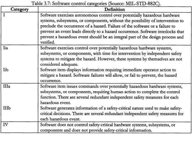
It is important to note that a software hazard criticality matrix is developed in MIL-STD-882C, the predecessor of MIL-STD-882D. It states:
The initial assessment of risk for software, and consequently software controlled or software intensive systems, cannot rely solely on the hazard severity and probability. Determination of the probability of failure of a single software function is difficult at best and cannot be based on historical data.
Subsequently, it introduces the concept of a mishap risk assessment matrix by potential hazard severity and software control categories, which demonstrate the degree of control that software exercises over the hardware. Software control categories are shown in Table 3.7, and a sample of a software risk assessment matrix based on software control categories is shown in Table 3.8. Although the concept of software control categories is eliminated in MIL-STD-882D, there is still a description of that in Software System Safety Handbook by Joint Software Safety Committee U.S. DoD (1997), which, Herrmann (1999) says, supplements MIL-STD-882D. (It is important to note that this approach is still controversial, and, for example, Leveson (2002) addresses counter opinions. She argues that the software that provides information to the human controller but does not directly issue control