Comparing the Efficacy of Fiber Reinforced
Actuators to Replicate Inhalation vs. Exhalation
by
Lyndie Zollinger
Submitted to the Department of Mechanical Engineering
in partial fulfillment of the requirements for the degree of
Bachelor of Science in Mechanical Engineering
at the
MASSACHUSETTS INSTITUTE OF TECHNOLOGY
May 2020
c
○ 2020 Massachusetts Institute of Technology. All rights reserved.
Signature of Author . . . .
Department of Mechanical Engineering
May 06, 2020
Certified by . . . .
Ellen Roche
Assistant Professor, Mechanical Engineering and Institute for Medical
Engineering and Science
Thesis Supervisor
Accepted by . . . .
Maria Yang
Professor of Mechanical Engineering
Undergraduate Officer
Comparing the Efficacy of Fiber Reinforced Actuators to
Replicate Inhalation vs. Exhalation
by
Lyndie Zollinger
Submitted to the Department of Mechanical Engineering on May 06, 2020, in partial fulfillment of the
requirements for the degree of
Bachelor of Science in Mechanical Engineering
Abstract
Fluid Powered Elastomeric Actuators are a class of soft robotic actuators of particular interest for biomimetic designs because researchers can replicate certain motions by tailoring the mechanical properties of the actuator through the use of different fibers and materials. [1] Hu et al. showed that pre-curved fiber-reinforced actuators could be used to mimic more complex geometries and motions. [2] Optimization techniques for determining optimal fabrication parameters for such actuators were developed by Hu et al. from a modified version of Connolly et al.’s technique to generate fiber-reinforced actuators optimized to follow a given input trajectory. [2, 1] This modified optimization technique was adapted for the specific application of creating biomimetic actuators to follow the motion of the human diaphragm. [2] The technology relies on extracting motion trajectories from clinical imaging data. This work analyzes and optimizes Hu et al.’s assumptions in visually choosing a planar location for the diaphragm anchoring point into the ribs based off of pixel locations within a Magnetic Resonance Imaging (MRI) scan in order to choose actuators to fabricate for further testing. We conducted a sensitivity analysis on the effect of varying this assumed anchoring point over a span of 3.1cm. We found no statistically significant differences in the mean error of the fabrication datasets corresponding to three selected anchoring location values. We determined that an assumed offset of 130 pixels (28.9 cm from the top of the image) provided an optimal compromise for minimizing error while still being a biologically realistic assumption. This fabrication dataset was thus selected for further development. Computer-aided design (CAD) models of the actuators were developed and used in creating molds. The actuators were then manufactured using the developed molds. Due to the complex nature of studying generated forces on a curved actuator, a modular test fixture compatible with minor modifications to the molds was developed for an Instron test setup. The test fixture was developed and prepared for testing. The future results of this testing will provide further insights into the feasibility of developing a soft robotic biomimetic diaphragm.
Thesis Supervisor: Ellen Roche
Title: Assistant Professor, Mechanical Engineering and Institute for Medical Engi-neering and Science
Acknowledgments
I wish to express my sincere gratitude to Lucy Hu for her constant guidance and support throughout this project, as well as Professor Ellen Roche for her support. They have provided immense encouragement, resources, and helpful suggestions for revision even through the outbreak of a global pandemic that caused MIT to close and modification to the thesis plans to be required. Their contributions have been essential to the completion of this work.
I would like to thank Luca Rosalia and Samuel Dutra Gollob for their help with ma-chinery training and questions about the Instron and 3D printer options available. I would also like to thank Robert Zollinger for his constant love, support, and encour-agement throughout this process. He kept me going and this work would not have been possible without him. I would also like to thank him for taking the time to proofread for typos and clarity of content.
I would like to thank Wade, Paula, Parker, Carlyn, MacKenzie, and Challie Mitchell for their support and encouragement throughout this process and help proofreading for typos.
Finally, I would like to thank Sandra Walters for providing support and accountability throughout the writing process.
Contents
1 Introduction 17
2 Validating Trajectory Offset Assumptions 21
2.1 Percentage of Error Comparisons . . . 21
2.2 Statistically Significant Differences . . . 22
2.2.1 Assessing the Unusually High Variance . . . 22
2.3 Biological Feasibility . . . 24
3 Constructing 3D Models of Actuators 31 3.1 Extruding Segment 1 . . . 33
3.2 Adding Sketches of Reinforcing Fibers . . . 33
3.2.1 Defining The Fiber Angle . . . 35
3.2.2 Defining The Start Angle . . . 35
3.3 Creating Tracks for Wrapping Fibers . . . 35
3.4 Creating Arcs to Define Initially Bent Segments . . . 36
3.5 Creating the Body of the Bent Segment . . . 38
3.6 Creating Fiber Sketches Along the Bent Segment . . . 39
3.6.1 Sketching Start Angles . . . 39
3.6.2 Creating a Surface Sweep . . . 40
3.6.3 Creating an Intersection Curve . . . 40
3.6.4 Creating the Remaining Fiber Sketches . . . 41
3.7 Creating Fiber Tracks on Bent Segments . . . 42
3.8 Creating Segment 3 . . . 43
3.8.1 Reference Geometry . . . 43
3.8.2 Extruding Segment 3 . . . 43
3.8.3 Creating Fiber Sketches and Cuts . . . 43
3.9 Preparing Actuators for Manufacturing . . . 44
3.9.1 Sealing Caps . . . 44
3.9.2 Adding Grooves for Wrapping Between Sections . . . 44
3.10 Preparing the Actuator CAD for Mold Making . . . 45
3.11 Creating CAD Molds . . . 47
3.12 Completing the Manufacturing Process . . . 48
4 Designing a Test Fixture 51
4.1 Initial Design Steps . . . 53
4.1.1 Refining Ideas . . . 53
4.2 Designing for Actuator Alignment . . . 53
4.3 Designing the Instron Attachment . . . 54
4.4 Designing to Prevent Interference and Undesired Movement . . . 56
4.5 Preparing for Testing on the Instron . . . 57
5 Conclusion 59
List of Figures
1-1 The blue represents a stiffer material. The left actuator shows a
counter-flexing, or straightening, actuator. As pressure is increased, the less stiff material on the inside edge causes the actuator to pref-erentially straighten. The right actuator shows a flexing, or bending, actuator. As pressure increases, the less stiff material on the outside
edge causes the actuator to preferentially bend further. . . 18
1-2 A coronal view of the diaphragm muscle attaching to the rib cage. Note
that the slope in the anterior side of the rib cage causes the diaphragm
to start in different cross-sectional planes. [3](modified) . . . 19
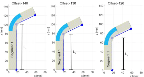
1-3 A comparison of the trajectories and output parameters for the three
offset values. Note the differences in the length of L1 and segment 1
for each offset value. . . 19
2-1 Hu et al.’s demonstration of the four configurations for a coronal
ex-tracted trajectory. Note the exex-tracted trajectory discretizes the curved trajectory into a segmented input for the optimization algorithm. The offset value corresponds with the pixel index of the y position of the
bottom-most point of the trajectory. [2] . . . 21
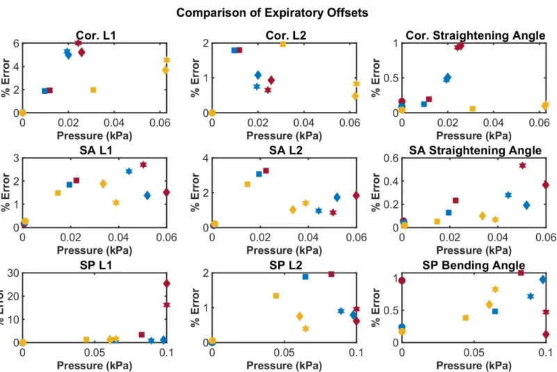
2-2 Comparison of the percentage of error for each offset option of each
expiration actuator in three critical trajectory components at four con-figurations in the trajectory. Note the variation between each actuator option in the optimized pressures for each of the four configurations. Also notice the variation in the y-axis scales between each motion and the variations in which offset value had the highest percentage of error for different trajectory components and configurations, without a dis-tinguishable pattern. Note the smaller maximum percentage of error for bending and straightening angles, supporting Hu et al.’s conclusion
of increased pneumatic efficiency. . . 26
2-3 Comparison of the percentage of error for each offset option of each
inspiration actuator in three critical trajectory components at four configurations in the trajectory. Note the variations in pressure and highest error for different configurations and the variation in the y-axis scales across each motion without a distinguishable pattern. Also note the unusually high error in the SP L1 segments which will be addressed
2-4 A Sagittal trajectory with offset=140. Note that the offset begins
below the point at which the abdomen begins to slope inwards. [2] . . 28
2-5 A comparison of the 126 and 130 offset values in the Sagittal Posterior
L1 segment. Note that the 126 offset produces higher error values in
all configurations. . . 29
3-1 Inspiration actuators (left) were optimized for the trajectory to lie on
the inside curve, while expiration actuators (right) were optimized for
the trajectory to lie on the outer curve. [2] . . . 31
3-2 In order to create physical models, the bend angles needed to be
con-verted into curved segments that would hold the resting bend angle.
[2] . . . 32
3-3 The first step is to create a solid extrusion with a diameter of 16.7mm
and the length of the first segment, 63.57mm for the Inspiration
Sagit-tal Posterior Actuator shown. . . 33
3-4 Parameters used to create the first Helix Spiral for the Inspiration
Sagittal Posterior actuator. The height is the length of the segment,
63.57mm, the revolutions were 𝑁𝑟𝑒𝑣 = 0.5571, and for the first fiber,
the start angle, 𝜑, was 0.00∘ in the clockwise direction. As the circle
sketches were drawn on the bottom face for this actuator, the reverse
direction was required. . . 34
3-5 Each set contains one clockwise and one counterclockwise fiber sketch,
as described in Section 3.2.2. The radial spacing between each spiral is equal. As the Inspiration Sagittal Posterior actuator has 11 fiber sets for the first segment, 𝜑𝑐𝑖 = 32.727∘·(𝑖−1) and 𝜑𝑐𝑐
𝑖 = 180∘+32.727∘·(𝑖−1)
for 𝑖 = 1, 2...𝑁𝑓 𝑖𝑏𝑒𝑟 𝑠𝑒𝑡𝑠. Each fiber in the segment uses the same fiber
angle α, the same height 𝐿, and the same number of revolutions 𝑁𝑟𝑒𝑣. 34
3-6 The fiber angle, α, as shown on Segment 1 of the Inspiration Sagittal
Posterior Actuator with one reinforcing fiber sketch shown. . . 35
3-7 (a) A sample radial start angle for a segment in which 𝑁𝑓 𝑖𝑏𝑒𝑟 𝑠𝑒𝑡𝑠 =
8, such as segment 3 of the Inspiration Coronal actuator. (b) The
corresponding start angles for all 8 fiber sets. Because 𝑁𝑓 𝑖𝑏𝑒𝑟 𝑠𝑒𝑡𝑠 is
even in this example, the same radial positions will be used for both the clockwise and counterclockwise fibers. That is, each radial position will have one clockwise and one counterclockwise fiber which begin there.
(For example, 𝜑𝑐 5 = 360∘ 8 ·(5−1) = 180 ∘, and 𝜑𝑐𝑐 1 = 180 ∘+360∘ 8 ·(1−1) =
180∘.) This is not the case when 𝑁𝑓 𝑖𝑏𝑒𝑟 𝑠𝑒𝑡𝑠 is odd, such as for the 11
fiber sets in Figure 3-5 of the Inspiration Sagittal Posterior segment 1. 36
3-8 A side-view of segment 1 of the Inspiration Sagittal Posterior actuator
with one set of fiber sketches shown. One fiber is sketched clockwise
and the other counterclockwise. The offset of 180∘ between the start
angles of the fibers ensures that the fibers meet at the mid-line of the
3-9 Creating a swept cut track for guiding the fibers during the manufactur-ing process. A track of diameter 0.35mm was used for manufacturmanufactur-ing purposes. The other fiber sketches in the Inspiration Sagittal Posterior
segment 1 are hidden for ease of viewing the cut sketch. . . 37
3-10 All fiber tracks cut into segment 1 of the Inspiration Sagittal Posterior
actuator. Note that they follow the same pattern as Figure 3-5 . . . . 38
3-11 Arc sketch defining the initially bent segment of the Inspiration Sagit-tal Posterior actuator. The radius of curvature and bend angle are shown. For convenience, segment 1 was extruded downward so that the coincident point on the top face of segment 1 is also coincident
with the origin. . . 38
3-12 Adding the body of segment 2 to segment 1 on the Inspiration Sagittal
Posterior actuator using the arc sketch from Section 3.4. . . 39
3-13 The solid body of segment 2 attached to segment 1 of the Inspiration Sagittal Posterior Actuator. Note that the diameter remains constant
through the bend. . . 39
3-14 The sketch of the line from the center of the actuator at the 𝜑 = 0∘
circumferential angle. Note how it is completely centered in the straight segment of the actuator and goes to the interior curve of the bent segment. The line was extended slightly beyond the interior edge for
convenience in later steps. . . 40
3-15 Creating a single surface sweep on the Inspiration Sagittal Posterior actuator. Sketch 37 is the line sketch drawn to the start angle, while Sketch 24 is the arc sketch used to create the body. The twist is defined by the number of revolutions, which is 0.9988 revolutions for segment 2 of this actuator. The arrow circle next to the Direction 1 box is
highlighted for the counterclockwise fibers. . . 41
3-16 A 3DSketch was generated using the intersecting curve feature. . . . 41
3-17 Creating the first track for wrapping fibers on the Inspiration Sagittal
Posterior bent segment. . . 42
3-18 Tracks for all 6 fiber sets of the Inspirational Sagittal Posterior actuator
bent segment. Notice how the fiber sets still intersect at the 𝜑 = 90∘
and 𝜑 = 270∘ circumferential angles, as they did for segment 1. This
indicates that the start angle sketches were input correctly. . . 42
3-19 A reference plane coincident with the face at the end of the bent seg-ment in the Inspiration Sagittal Posterior actuator. Note that there is no planar offset from the face. The reference point is also shown in the
center of the face of the end of the bent segment. . . 43
3-20 Extruding segment 3 of the Inspiration Sagittal Posterior actuator.
Note the length of 30.74mm as shown in Table 3.1. . . 44
3-21 The helix spirals were again defined using height and revolution and
the parameters found in Table 3.1. . . 44
3-22 Complete fiber tracks across all three segments of the Inspiration Sagit-tal Posterior actuator. Note that the opposing fibers of each set cross
3-23 A 5mm cap was added to each end of the actuator. . . 45 3-24 An example of fibers wrapped through the groove. This area is used
as a firm base location to tie fibers down so that fiber and start angles can change between segments. This also helps increase the rigidity
between sections, as the optimization algorithm assumed. . . 46
3-25 Reference axes along the center of the straight segments of the
Inspi-ration Sagittal Posterior actuator. . . 46
3-26 The leftmost vertical line represents 𝜑 = 180∘, and the rightmost
rep-resents 𝜑 = 0∘. The circle is centered on the edge of the actuator and
the line separating the two segments. . . 46
3-27 The groove is cut around the entire circumference of the actuator. Note that both grooves on each straight segment can be cut at the same time by sketching both circles in the same sketch and using this Revolved
Cut feature. . . 47
3-28 The completed CAD of the Inspiration Sagittal Posterior actuator.
Note all four wrapping grooves, as well as both sealing caps and cores. 47
3-29 A 20.32mm box was sketched uniformly around each of the extending segments. Using parallel constraints, the boxes were then connected over the bent portion of the actuator. Note that the box also covers
the end of the core. . . 48
3-30 The outer mold of the Inspiration Sagittal Posterior straightening ac-tuator was split along the segment lines shown in blue to create three new bodies. Note that the direction of the teeth used for aligning the
molds indicates this is the top half of the mold. . . 49
3-31 The inner mold of the Expiration Sagittal Posterior bending actuator was split along the segment lines as shown in blue. Note the tooth
pattern indicating that this is the bottom half of the actuator mold. . 49
3-32 A sample split line for the second segment mold of the bending
actua-tors on the Expiration Sagittal Posterior mold segment. . . 50
3-33 A sample aligning piece for segment 2 of the Inspiration Sagittal Pos-terior mold. Note that for bending actuators this was again split along
the center line for removal due to geometric constraints. . . 50
4-1 The force produced by the outer face of the third segment on the
left represents the straightening force exerted by the actuator while following the diaphragm motions. On the right, the bending force of
the actuator is measured from the inside face of the third segment. . . 51
4-2 A close up of the compression plates used on the Instron 5944. . . 52
4-4 Left, a sample straightening mold with a modular insertion piece. Note the alignment of segment three such that if the actuator were placed inside the mold the outer face of segment 3 would be parallel to the top plate of the Instron, as desired. Right, a sample bending mold with a modular insertion piece. Note that the alignment of segment three allows the inside face of the actuator to be parallel to the top plate of
the Instron as desired. . . 54
4-5 The modular fixture plate for the bottom testing plate. Note that it is
compatible with all actuators. . . 55
4-6 A side aligning piece for attachment to the Instron. Note that the holes
at the top are clearance holes for the threads in the fixture plate, while the holes at the bottom are close fit for the built-in threaded holes in
the Instron plates. . . 55
4-7 A side view and isometric view of the Instron attachment for modular
compatibility. . . 55
4-8 The extension piece for testing straightening angles. The top portion
is designed to be compatible with the insertion piece of any actuator mold and can easily be removed from the fixture plate and mold as
needed. . . 56
4-9 The extension piece and mold aligner in place for use with the
Inspi-ration Sagittal Posterior Actuator. . . 57
4-10 The top fixture to avoid interference of other actuator segments. Note the curved bottom designed to ensure uniform contact with the outside
curvature of the actuator. . . 58
4-11 A full testing setup for the Expiratory Sagittal Posterior Actuator tests. 58
A-1 The extracted trajectory input with a visualization of the output pa-rameters for the Expiration Coronal actuator with offset=130. Note that for expiration actuators the input trajectory was optimized for
the outside curve of the actuator as shown. . . 64
A-2 The extracted trajectory input with a visualization of the output pa-rameters for the Expiration Sagittal Anterior actuator with offset=130. Note that for expiration actuators the input trajectory was optimized
for the outside curve of the actuator as shown. . . 65
A-3 The extracted trajectory input with a visualization of the output pa-rameters for the Expiration Sagittal Posterior actuator with offset=130. Note that for expiration actuators the input trajectory was optimized for the outside curve of the actuator as shown. Also note that for this actuator, the first segment is required to undergo a large amount of shrinkage to follow the trajectory. This is an area where current elastomeric actuator techniques fall short. As such, this segment is approaching a boundary limit for the capabilities of the optimization
A-4 The extracted trajectory input with a visualization of the output pa-rameters for the Inspiration Coronal actuator with offset=130. Note that for inspiration actuators the input trajectory was optimized for
the inside curve of the actuator as shown. . . 67
A-5 The extracted trajectory input with a visualization of the output pa-rameters for the Inspiration Sagittal Anterior actuator with offset=130. Note that for inspiration actuators the input trajectory was optimized
for the inside curve of the actuator as shown. . . 68
A-6 The extracted trajectory input with a visualization of the output pa-rameters for the Inspiration Sagittal Posterior actuator with offset=130. Note that for inspiration actuators the input trajectory was optimized for the inside curve of the actuator as shown. Also note that for this actuator, the first segment is required to undergo a large amount of shrinkage to follow the trajectory. This is an area where current elas-tomeric actuator techniques fall short. As such, this segment is ap-proaching a boundary limit for the capabilities of the optimization
List of Tables
2.1 Variance of the offset Error Percentage Data . . . 22
2.2 F-test p-values . . . 23
2.3 Student t-test p-Values . . . 23
2.4 Variance of the Revised Offset Error Percentage Data . . . 23
2.5 F-test p-values . . . 24
2.6 Student t-test p-values . . . 24
3.1 CAD Parameters for Offset=130 . . . 32
3.2 Fiber Set Start Angles for 𝑁𝑓 𝑖𝑏𝑒𝑟 𝑠𝑒𝑡𝑠 = 11 . . . 37
4.1 Design Requirements of the Test Fixture . . . 52
1.
Introduction
Bioinspired robotics is a growing field that seeks to reverse-engineer complex struc-tures and motions found in biological systems in order to achieve desired capabilities. [4, 2] However, nature is full of examples of complex and curved geometries, such as the domed musculature of the human diaphragm, that present a challenge for biolog-ical actuators. Resting geometries are key to achieving proper functions in complex and curved actuators such as these. [2]
The field of soft robotics has recently seen significant progress in many applica-tions, including bioinspired motions. [1, 5] Fluid-powered elastomeric actuators, a class of soft robots, are able to generate complex output motions using a relatively simple controlled input of pressure which changes mechanical properties in the actua-tor. [1] Cylindrical fiber-reinforced actuators are one type of fluid-powered elastomeric actuator which can be tuned to produce extending, twisting, and bending motions. Extending actuators can lengthen or contract, depending on the fiber angles, while twisting actuators generate rotation about the center axis of the actuator. Bending actuators utilize material changes and fiber angles to generate a bend angle. [6, 2] A bending segment consists of a two-material elastomer in which one material is stiffer than the other, causing the less stiff material to preferentially deform and create a bend angle. [2]
Connolly et al. proposed a method of combining an analytical model and opti-mization techniques to determine the optimal design parameters for an actuator to achieve a desired trajectory with pressurization. [1] However, this technique was used only for initially straight geometries, limiting its use to only a portion of the pneu-matic range. Hu et al. expanded upon this optimization technique to account for pre-curved actuators by adding an additional variable, the resting bend angle. [2] The resting bend angle is described by the angle inscribed by the initially concave side of the actuator. [2] Depending on the orientation of the stiffer and less stiff elastomers, the bend angle of the concave side upon positive pressurization may either increase or decrease from the resting bend angle. Thus, pre-curved actuators may be classified as either flexing actuators (increasing bend angle) or counter-flexing actuators (de-creasing bend angle), as shown in Figure 1-1. These two actuator classifications can also be referred to as bending (flexing) or straightening (counter-flexing) actuators in cases where the actuator is not pressurized such that a bending or straightening actuator would proceed past the point at which it would become fully "bent" or fully "straight". This is the case with the applications discussed below. [2]
Hu et al. applied this optimization technique to the trajectory of the human di-aphragm. The diaphragm was examined from two planar views and three trajectories,
Figure 1-1: The blue represents a stiffer material. The left actuator shows a counter-flexing, or straightening, actuator. As pressure is increased, the less stiff material on the inside edge causes the actuator to preferentially straighten. The right actuator shows a flexing, or bending, actuator. As pressure increases, the less stiff material on the outside edge causes the actuator to preferentially bend further.
Coronal, Sagittal Anterior, and Sagittal Posterior, were obtained by image analysis of an MRI recording of a healthy diaphragm expanding and contracting from Mankodi et al.. [2, 7]
Analyzing these trajectories required making assumptions using the diaphragm in the MRI recording as an anchoring point. The human diaphragm does not begin from a single transverse cross-sectional plane of the body. The diaphragm anchors to the rib cage, which, due to the curved nature of the rib cage, inherently causes the bottom to not align with a single flat cross-sectional plane, as shown in Figure 1-2. However, Hu et al. made the simplifying assumption of a diaphragm that begins at the same offset transverse cross-sectional plane from both planes of view. This assumption was made due to manufacturing limitations in replicating the curved nature of the rib cage. This limitation is also partly due to the limitations of the data obtained from only two MRI planes of view. This restricts the resolution at which data can be accurately measured in attempting to capture the full curvature of the rib cage. This is accepted as a limitation of this work; to compensate, it also requires finding an offset transverse cross-sectional plane location of the start of the diaphragm that minimizes the error from this simplifying assumption. [2]
To do this, three potential offset values from the top of the image were used as the starting point of the diaphragm muscle to create trajectories, one corresponding to a feasible starting point for the lowest parts of the diaphragm (offset of 140, 31.1cm below the top of the image), one corresponding to a feasible starting point for the highest points in the diaphragm (offset of 126, 28cm below the top of the image), and one between the two options (offset of 130, 28.9cm below the top of the image). The numerical offset value corresponds to pixel indices below the top of the image which were then translated to a y height as shown in Figure 2-1. As the top of the image does
Figure 1-2: A coronal view of the diaphragm muscle attaching to the rib cage. Note that the slope in the anterior side of the rib cage causes the diaphragm to start in different cross-sectional planes. [3](modified)
not hold biological significance, it is the differences in length between the three offset values that holds the most significance. For physical understanding of the differences between pixel indices, Hu et al. determined a scaling factor of 9𝑝𝑖𝑥𝑒𝑙𝑠2𝑐𝑚 . This indicates the offset-of-130 dataset utilizes an anchoring point 2.2cm above the offset-of-140’s anchoring point. A visualization of the trajectory differences and output parameter differences the offsets can make is shown in Figure 1-3. The offset-of-126 dataset utilizes an anchoring point 0.89cm above that of the offset-of-130 dataset, and 3.1cm above that of the offset-of-140 dataset. The optimization technique was then applied to generate potential fabrication datasets for all three trajectories. The extracted trajectory inputs and visualizations of the output parameters for the offset-of-130 case are shown in Appendix A.
Figure 1-3: A comparison of the trajectories and output parameters for the three offset values. Note the differences in the length of L1 and segment 1 for each offset value.
2.
Validating Trajectory Offset Assumptions
Although Hu et al. successfully applied an optimization technique to the trajectory of the human diaphragm, the assumptions they made in doing so remained to be jus-tified. In this chapter, their assumptions were evaluated using error assessments and from the standpoint of what could be biologically realistic to determine which offset was used for fabrication and further testing to minimize the error of the simplifying assumption to begin the diaphragm on the same cross-sectional plane.
2.1
Percentage of Error Comparisons
To begin assessment of the validity of the offset assumptions, the percentage of error of three critical trajectory components in each actuator were compared: the length of the first segment, the bending or straightening angle, and the length of the second segment. Each actuator had previously been measured in four configurations cor-responding to four motion locations in the trajectory, as shown in Figure 2-1. The optimization technique determined the optimal pressure for each configuration, and each type of actuator at each offset value had a different pressure value. However, these pressure values are consistent for the three critical aspects of motion in each type of offset and actuator, as shown in Figure 2-2 and Figure 2-3.
Figure 2-1: Hu et al.’s demonstration of the four configurations for a coronal ex-tracted trajectory. Note the exex-tracted trajectory discretizes the curved trajectory into a segmented input for the optimization algorithm. The offset value corresponds with the pixel index of the y position of the bottom-most point of the trajectory. [2] Upon visual comparison, the offsets tend to have error percentages close to the same order of magnitude for each piece. There is some variation in which offset had the highest error for different configurations and critical trajectory components. It is im-portant to note that the calculation of the percentage of error requires one to divide
by the original length of the trajectory for some of the critical trajectory components. This suggests that higher offsets would tend towards lower error percentages because of the longer offset length. Thus, further statistical analysis and biological feasibility were needed to assess which offset values to proceed further with.
2.2
Statistically Significant Differences
To further compare the error percentages of each offset value, a two-tailed t-test was performed to find statistically significant differences between each offset and the other two offsets. To do so, the percentage-of-error data sets were concatenated to combine all expiration and inspiration actuators into a single vector for each offset value con-sisting of 24 data points of error percentages.
The variance of each of the three data sets was then evaluated, as shown in Ta-ble 2.1. The unusually high variance in these data sets will be addressed further in Section 2.2.1. An F-test was performed to assess whether the three data sets had statistically significantly different variances. A null hypothesis of no difference in variance was used. The p-values are shown in Table 2.2. All were found to have statistically significant variance differences (p-values < 0.05, indicated in blue). A t-test for unequal variances was then performed. The t-test evaluated a null hy-pothesis of no difference. No statistically significant differences were found between the three offsets. The resulting p-values of each t-test are shown in Table 2.3.
Table 2.1: Variance of the offset Error Percentage Data
Mean Variance
offset=126 4.6 268.2
offset=130 3.3 126.2
offset=140 2.1 32.4
2.2.1
Assessing the Unusually High Variance
It is noted that the Sagittal Posterior L1 data, shown in Figures A-3 and A-6, pro-duced unusually high error values. This is likely due to the trajectory requiring a large percentage of shrinkage in this segment. Large segment shrinkage is an area in which designs of elastomeric actuators generally fall short. It is clear this is approach-ing a boundary limit for this optimization algorithm. We accept this as a limitation in using this type of actuator. As such, both Sagittal Posterior L1 data points were removed from each offset to be compared separately, and the mean and variance of
Table 2.2: F-test p-values
offset=126 offset=130 offset=140
offset=126 - 0.0018 2.2e-16
offset=130 0.0018 - 3.6e-8
offset=140 2.2e-16 3.6e-8
-Table 2.3: Student t-test p-Values
offset=126 offset=130 offset=140
offset=126 - 0.565 0.2124
offset=130 0.565 - 0.414
offset=140 .2124 0.414
-the revised offset data sets were -then calculated, as shown in Table 2.4. The vari-ances were again compared for statistically significant differences, and the p-values are shown in Table 2.5.
As all datasets were found to not have statistically significant differences in vari-ance, a two-tailed t-test for equal variances was performed. A null hypothesis of no differences between the offset error percentages was again tested, and, again, no sta-tistically significant differences were found. The p-values are shown in Table 2.6. As no statistically significant differences in the percentage of error were found between the three offset values, further analysis to determine which parameters to proceed with was required.
Table 2.4: Variance of the Revised Offset Error Percentage Data
Mean Variance
offset=126 1.62 5.1
offset=130 1.66 5.5
Table 2.5: F-test p-values
offset=126 offset=130 offset=140
offset=126 - 0.7674 0.1606
offset=130 0.7674 - 0.0899
offset=140 0.1606 0.0899
-Table 2.6: Student t-test p-values
offset=126 offset=130 offset=140
offset=126 - 0.9175 0.3776
offset=130 0.9175 - 0.3299
offset=140 0.3776 0.3299
-2.3
Biological Feasibility
The offset values were then assessed for biological feasibility to determine which pa-rameter set to proceed with. To do so, the realistic locations in which the diaphragm could feasibly start were reassessed from the initial decisions described above. As shown in Figure 2-4, the offset of 140 produces trajectories which begin below the point of recession of the abdomen from Sagittal viewpoints. The offset of 140 is bio-logically incompatible with the sagittal anterior trajectory. Therefore, it was decided not to move forward with the offset-of-140 parameters.
The offset-of-126 and offset-of-130 trajectories began in areas which were considered to be more biologically feasible. To ultimately determine which of these two actua-tors to use, we revisited the extremely high SP L1 errors to minimize the percentage of error in the most difficult segment of the diaphragm modeling. The offset-of-130 segments were found to have lower errors in all configurations as shown in Figure 2-5. Additionally, as described in the Introduction, the offset of 126 was designed to match feasible locations in which higher planes of diaphragm would be found. Thus, even if visible incompatibilities are not seen as with the 140 case, it is also likely that the offset of 126 is too short for biological feasibility in certain parts of the viewpoints. Therefore, the parameters for the offset 130 case were ultimately chosen to proceed
with further testing.
This validation has highlighted some of the shortcomings of the optimization tech-nique and the use of this type of actuator. However, it has been shown that achieving the complex motions of a diaphragm is made more accurate by the use of pre-curved actuators in the optimization algorithm. [2] We opt for this higher degree of accuracy at the expense of the increased computational and manufacturing costs of optimized pre-curved actuators. Using statistical and biological analysis we demonstrated that using the offset-of-130 transverse cross-sectional plane would provide the best option for minimizing errors due to the assumption of the diaphragm beginning along the same transverse plane. We therefore determined to use these fabrication parameters for further testing.
Figure 2-2: Comparison of the percentage of error for each offset option of each expiration actuator in three critical trajectory components at four configurations in the trajectory. Note the variation between each actuator option in the optimized pressures for each of the four configurations. Also notice the variation in the y-axis scales between each motion and the variations in which offset value had the highest percentage of error for different trajectory components and configurations, without a distinguishable pattern. Note the smaller maximum percentage of error for bending and straightening angles, supporting Hu et al.’s conclusion of increased pneumatic efficiency.
Figure 2-3: Comparison of the percentage of error for each offset option of each inspiration actuator in three critical trajectory components at four configurations
in the trajectory. Note the variations in pressure and highest error for different
configurations and the variation in the y-axis scales across each motion without a distinguishable pattern. Also note the unusually high error in the SP L1 segments which will be addressed further in Section 2.2.1
Figure 2-4: A Sagittal trajectory with offset=140. Note that the offset begins below the point at which the abdomen begins to slope inwards. [2]
Figure 2-5: A comparison of the 126 and 130 offset values in the Sagittal Posterior L1 segment. Note that the 126 offset produces higher error values in all configurations.
3.
Constructing 3D Models of Actuators
After deciding to move forward with testing the optimization parameters of the 130 offset case, work began to develop CAD models of the actuators which could later be used to develop molds for manufacturing. This required some further manipulation of the parameters to account for the curved segment of the actuator. The arc length and bend angle were specified as outputs from the optimization technique. These parameters were then used to find the radius of curvature. It is noted that Inspiratory actuators were optimized for the two segment lengths to lie on the inside curve of the actuator, while Expiratory actuators were optimized for the trajectory lengths to be on the outer curve, as shown in Figure 3-1. With the radius of curvature 𝜌, and bend angle 𝜓, the segment lengths could be adjusted to include the arc, as shown in Figure 3-2. An equal amount 𝑥 was removed from each of the straight segment lengths to give the final lengths of segment 1 and segment 3, thus bisecting the arc.
Using trigonometry, 𝑥 = 𝜌 * 𝑡𝑎𝑛(𝜓2). The length of segment 2 was determined using
the bend angle and radius of curvature.
Figure 3-1: Inspiration actuators (left) were optimized for the trajectory to lie on the inside curve, while expiration actuators (right) were optimized for the trajectory to lie on the outer curve. [2]
Figure 3-2: In order to create physical models, the bend angles needed to be con-verted into curved segments that would hold the resting bend angle. [2]
The final parameters were then determined to be as shown in Table 3.1. Visu-alizations for the output parameters of all six actuators are shown in Appendix A. SolidWorks 2018 was used to create CAD models based off of these parameters. The derivation of three parameters -number of revolutions, fiber angle, and number of fibers- is explained further in Section 3.2. Using these parameters, a series of steps was utilized to develop a CAD model for all six actuators in SolidWorks. Note that, where possible, Global Parameters were defined in SolidWorks and used to make it easier to modify actuators in the future if needed.
Table 3.1: CAD Parameters for Offset=130
Actuator Exp, Cor Exp, SA Exp, SP Insp, Cor Insp, SA Insp, SP
Segment 1 Length (mm) 38.23 48.21 21.66 69.38 59.16 63.57 Fiber angle, α (∘) 5 26.2 5 63.23 55.66 65.31 N fiber sets 1 5 1 11 10 11 N revolutions 8.3289 1.8675 4.7189 0.6671 0.7704 0.5571 Segment 2 Length (mm) 78.56 41.1 20 32.77 43.51 30 Fiber angle, α (∘) 13.55 16.96 24.07 7.3 16.97 29.79 N fiber sets 3 4 5 2 4 6 Initial bend (∘) 99.58 87.33 54.62 73.1 65.56 63.56 Radius of Curvature 36.8514 18.6151 12.6298 34.0351 46.3753 35.3933 N revolutions 3.9177 0.9779 0.1741 4.8758 2.7177 0.9988 Segment 3 Length (mm) 3.75 21.19 43.4 27.24 22.21 30.74 Fiber angle, α (∘) 5 25.09 47.74 41.78 57.25 27.97 N fiber sets 1 5 9 8 10 6 N revolutions 0.8170 0.8626 0.7517 0.5811 0.2723 1.1033
3.1
Extruding Segment 1
First, a circle of diameter 16.7mm was sketched and extruded to the parameter length of segment 1 found in Table 3.1, ensuring the origin was at the center of the circle being extruded. An example of the Inspiration Sagittal Posterior actuator is shown in Figure 3-3.
Figure 3-3: The first step is to create a solid extrusion with a diameter of 16.7mm and the length of the first segment, 63.57mm for the Inspiration Sagittal Posterior Actuator shown.
3.2
Adding Sketches of Reinforcing Fibers
To create sketches of the reinforcing fibers, we must first define the fiber angle α as described in Section 3.2.1. Equation 3.2 was then used to determine the number of fibers required for each segment. The number of fibers required for each segment was then used to determine each fiber’s start angle 𝜑 as explained in Section 3.2.2. Finally, the number of revolutions was defined using Equation 3.1, where 𝐷 is the outside diameter (16.7mm) and 𝐿 is the length (or height) of the segment as stated in Table 3.1.
A Helix Spiral (Insert -> Curve -> Helix Spiral in SolidWorks) was then inserted from a circular sketch of diameter 16.7mm drawn on either the top or bottom face of the segment. The spiral was defined by height and revolution, as shown in Figure 3-4, with height 𝐿. The reverse direction could be checked or unchecked to ensure the spiral followed the direction of the actuator depending on whether the top or bottom face was used to draw the circular sketch. A single fiber sketch is shown in Figure 3-4.
𝑁𝑟𝑒𝑣 =
𝐿
𝜋𝐷 tan(𝛼) (3.1)
𝑁𝑓 𝑖𝑏𝑒𝑟 𝑠𝑒𝑡𝑠 = max{round(12 sin 𝛼), 1} (3.2)
The remaining fiber sketches were then added to each segment, taking care to ensure that the circular sketch base of the helix spiral was on the same face for every
Figure 3-4: Parameters used to create the first Helix Spiral for the Inspiration Sagittal Posterior actuator. The height is the length of the segment, 63.57mm, the
revolutions were 𝑁𝑟𝑒𝑣 = 0.5571, and for the first fiber, the start angle, 𝜑, was 0.00∘
in the clockwise direction. As the circle sketches were drawn on the bottom face for this actuator, the reverse direction was required.
fiber in that segment (i.e., the circular sketch was not drawn on the top face for one fiber and the bottom face of another fiber in segment 1). The height and revolutions used to define the spiral was the same for each fiber within the segment, but the start angle and whether the spiral was clockwise or counterclockwise was changed as described in Section 3.2.2. An example of the full fiber set sketches for the Inspiration Sagittal Posterior actuator is shown in Figure 3-5.
Figure 3-5: Each set contains one clockwise and one counterclockwise fiber sketch, as described in Section 3.2.2. The radial spacing between each spiral is equal. As the Inspiration Sagittal Posterior actuator has 11 fiber sets for the first segment, 𝜑𝑐𝑖 = 32.727∘· (𝑖 − 1) and 𝜑𝑐𝑐
𝑖 = 180∘+ 32.727∘· (𝑖 − 1) for 𝑖 = 1, 2...𝑁𝑓 𝑖𝑏𝑒𝑟 𝑠𝑒𝑡𝑠. Each
fiber in the segment uses the same fiber angle α, the same height 𝐿, and the same
3.2.1
Defining The Fiber Angle
The fiber angle α is defined as shown in Figure 3-6. The fiber angle was determined using Hu et al.’s optimization technique. The optimized values for α are shown in Table 3.1.
Figure 3-6: The fiber angle, α, as shown on Segment 1 of the Inspiration Sagittal Posterior Actuator with one reinforcing fiber sketch shown.
3.2.2
Defining The Start Angle
The start angle references the radial position, or circumferential angle, at which the fiber begins, as shown in Figure 3-7a. Each fiber set contains one fiber sketched in the clockwise direction, as shown in Figure 3-4, and one fiber sketched in the
counter-clockwise direction. The counter-clockwise start angles 𝜑𝑐
𝑖 are determined using Equation 3.3,
and the counterclockwise start angles 𝜑𝑐𝑐𝑖 are determined using Equation 3.4.
𝜑𝑐𝑖 = 360 ∘ 𝑁𝑓 𝑖𝑏𝑒𝑟 𝑠𝑒𝑡𝑠 (𝑖 − 1), 𝑖 = 1, 2...𝑁𝑓 𝑖𝑏𝑒𝑟 𝑠𝑒𝑡𝑠 (3.3) 𝜑𝑐𝑐𝑖 = 180∘ + 360 ∘ 𝑁𝑓 𝑖𝑏𝑒𝑟 𝑠𝑒𝑡𝑠 (𝑖 − 1), 𝑖 = 1, 2...𝑁𝑓 𝑖𝑏𝑒𝑟 𝑠𝑒𝑡𝑠 (3.4)
The offset of 180∘ for the counterclockwise spirals ensures that the fibers cross at
the mid-line of the actuator side, as shown in Figure 3-8. An example of the start angles for the 11 fiber sets of segment 1 of the Inspiration Sagittal Posterior actuator is shown in Table 3.2. The seams for material changes are defined to happen at
𝜑 = 90∘ and 𝜑 = 270∘ as shown in Figure 1-1.
3.3
Creating Tracks for Wrapping Fibers
Next, a track for aligning the fibers as they are wrapped was cut. The Swept Cut feature was used with the circular profile of the first Helix Spiral sketch, as shown in Figure 3-9. The remaining tracks were then cut for each fiber in the segment, as shown in Figure 3-10.
(a) (b)
Figure 3-7: (a) A sample radial start angle for a segment in which 𝑁𝑓 𝑖𝑏𝑒𝑟 𝑠𝑒𝑡𝑠 = 8,
such as segment 3 of the Inspiration Coronal actuator. (b) The corresponding start angles for all 8 fiber sets. Because 𝑁𝑓 𝑖𝑏𝑒𝑟 𝑠𝑒𝑡𝑠 is even in this example, the same radial
positions will be used for both the clockwise and counterclockwise fibers. That is, each radial position will have one clockwise and one counterclockwise fiber which begin there. (For example, 𝜑𝑐5 = 3608∘· (5 − 1) = 180∘, and 𝜑𝑐𝑐
1 = 180∘+360
∘
8 · (1 − 1) = 180
∘.)
This is not the case when 𝑁𝑓 𝑖𝑏𝑒𝑟 𝑠𝑒𝑡𝑠 is odd, such as for the 11 fiber sets in Figure 3-5
of the Inspiration Sagittal Posterior segment 1.
Figure 3-8: A side-view of segment 1 of the Inspiration Sagittal Posterior actuator with one set of fiber sketches shown. One fiber is sketched clockwise and the other
counterclockwise. The offset of 180∘ between the start angles of the fibers ensures
that the fibers meet at the mid-line of the side-view, as shown.
during initial manufacturing to aid in holding the fibers through the manufacturing process. After manufacturing the first actuator, it was found that the track was still too small and the fibers would slip out during the manufacturing process, so the diameter of the cut was increased to 0.35mm for future iterations. Exploring the effect of expanding the diameter of each track on the properties of the actuator is an area for potential future exploration.
3.4
Creating Arcs to Define Initially Bent Segments
To begin segment 2 (the initially bent segment), an arc was used to define the body of the segment. The bend angle and arc length given in the optimization parameters were used to determine the radius of curvature. A Centerpoint Arc was sketched such that one end of the arc was coincident with the center of the top face of segment 1
Table 3.2: Fiber Set Start Angles for 𝑁𝑓 𝑖𝑏𝑒𝑟 𝑠𝑒𝑡𝑠 = 11
Fiber Set Clockwise 𝜑 Counterclockwise 𝜑
1 0∘ 180∘ 2 32.727∘ 212.727∘ 3 65.45∘ 245.45∘ 4 98.18∘ 278.18∘ 5 130.909∘ 310.909∘ 6 163.636∘ 343.636∘ 7 196.36∘ 16.36∘ 8 229.09∘ 49.09∘ 9 261.818∘ 81.818∘ 10 294.545∘ 114.545∘ 11 327.27∘ 147.27∘
Figure 3-9: Creating a swept cut track for guiding the fibers during the manufac-turing process. A track of diameter 0.35mm was used for manufacmanufac-turing purposes. The other fiber sketches in the Inspiration Sagittal Posterior segment 1 are hidden for ease of viewing the cut sketch.
in each actuator. As shown in Figure 3-11, the center point was defined using a line coplanar with the top face and having a length equal to the radius of curvature. The bend angle and radius of curvature were then used to define the full trajectory of the bent segment as shown in Figure 3-11.
Figure 3-10: All fiber tracks cut into segment 1 of the Inspiration Sagittal Posterior actuator. Note that they follow the same pattern as Figure 3-5
.
Figure 3-11: Arc sketch defining the initially bent segment of the Inspiration
Sagit-tal Posterior actuator. The radius of curvature and bend angle are shown. For
convenience, segment 1 was extruded downward so that the coincident point on the top face of segment 1 is also coincident with the origin.
3.5
Creating the Body of the Bent Segment
The Swept Boss/Base feature was used with the circular profile of the arc sketch, as shown in Figure 3-12. A diameter of 16.7mm was again used, as shown in Figure 3-13, to be continuous with segment 1.
Figure 3-12: Adding the body of segment 2 to segment 1 on the Inspiration Sagittal Posterior actuator using the arc sketch from Section 3.4.
Figure 3-13: The solid body of segment 2 attached to segment 1 of the Inspiration Sagittal Posterior Actuator. Note that the diameter remains constant through the bend.
3.6
Creating Fiber Sketches Along the Bent Segment
3.6.1
Sketching Start Angles
To begin adding fiber sketches along the bent segment, a sketch with a single line was drawn on the plane between segments 1 and 2. For the initial starting angle,
of the bent segment, as shown in Figure 3-14. This location was defined to be the
0∘ circumferential angle, and all other start angles for the bent segment are defined
relative to this location. Each fiber sketch required drawing a new sketch on this same plane with a single line along the start angle 𝜑 for that fiber, as calculated using Equation 3.3 or Equation 3.4.
Figure 3-14: The sketch of the line from the center of the actuator at the 𝜑 = 0∘
circumferential angle. Note how it is completely centered in the straight segment of the actuator and goes to the interior curve of the bent segment. The line was extended slightly beyond the interior edge for convenience in later steps.
3.6.2
Creating a Surface Sweep
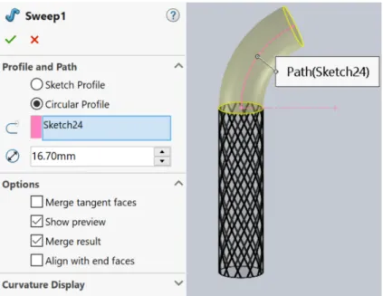
A Surface Sweep was then added (Insert -> Surface -> Sweep) and defined using a sketch profile. The line sketch along the start angle was used as the profile sketch, while the arc sketch created in Section 3.4 was used as the path, as shown in Figure 3-15. The Options section was used to specify a Twist Value controlled by Revolutions.
The number of revolutions 𝑁𝑟𝑒𝑣 was calculated using Equation 3.5, where 𝐷 is the
diameter of the actuator, 𝜓 is the initial bend angle in radians, and 𝛼 is the fiber angle
(in degrees) output from the optimization technique. The length 𝐿2 was defined as the
arc length of the outer curve of the actuator and was determined using Equation 3.6, where 𝜌 is the radius of curvature of the bent segment and 𝜓 is the same as in Equation 3.6. The direction of the revolutions was reversed for the counterclockwise fibers. 𝑁𝑟𝑒𝑣 = 𝐿2− 𝜓𝐷 𝜋𝐷 tan(𝛼) (3.5) 𝐿2 = 𝜓(𝜌 + 𝐷 2) (3.6)
3.6.3
Creating an Intersection Curve
Next, the intersection curve feature (Tools -> Sketch Tools -> Intersection Curve) was used to define the sketch of the fiber between the surface sweep and the outer face of the bent segment, as shown in Figure 3-16.
Figure 3-15: Creating a single surface sweep on the Inspiration Sagittal Posterior actuator. Sketch 37 is the line sketch drawn to the start angle, while Sketch 24 is the arc sketch used to create the body. The twist is defined by the number of revolutions, which is 0.9988 revolutions for segment 2 of this actuator. The arrow circle next to the Direction 1 box is highlighted for the counterclockwise fibers.
Figure 3-16: A 3DSketch was generated using the intersecting curve feature.
3.6.4
Creating the Remaining Fiber Sketches
The remaining fiber sketches were added by first creating the line sketch of the start angle using the process outlined in Section 3.2.2 and Section 3.6.1, then creating the surface sweep as demonstrated in Section 3.6.2, and lastly finding the intersection curve as shown in Section 3.6.3. Since the intersection curve is based off of the face of the segment body, intersection curves for all fibers were sketched before cutting any fiber tracks with the sketches. This helped to avoid SolidWorks errors. For convenience and aesthetics in the remaining steps, each surface sweep was hidden from view after the corresponding intersection curve was made.
3.7
Creating Fiber Tracks on Bent Segments
Tracks for wrapping the fibers were then cut using the Swept Cut feature and each corresponding 3DSketch as shown in Figure 3-17. As described in Section 3.3, the initial cut diameter of 0.254mm was later revised to 0.35mm to aid with manufactur-ing. This process was then used to cut a track for each fiber on each bent segment, as shown in Figure 3-18. Occasionally, unknown errors occurred in SolidWorks that required either a larger or smaller diameter than 0.35mm to be used and then in-cremented to the closest possible value to 0.35mm that would not cause the error.
Figure 3-17: Creating the first track for wrapping fibers on the Inspiration Sagittal Posterior bent segment.
Figure 3-18: Tracks for all 6 fiber sets of the Inspirational Sagittal Posterior actuator
bent segment. Notice how the fiber sets still intersect at the 𝜑 = 90∘ and 𝜑 = 270∘
circumferential angles, as they did for segment 1. This indicates that the start angle sketches were input correctly.
3.8
Creating Segment 3
3.8.1
Reference Geometry
To make adding helix spiral sketches and swept cuts more convenient, a reference plane was added on the end face of the bent segment, as shown in Figure 3-19. A reference point was also added on the reference plane in the center of the actuator as shown in Figure 3-19. This enabled sketching circles with a continuous center line for future steps.
Figure 3-19: A reference plane coincident with the face at the end of the bent segment in the Inspiration Sagittal Posterior actuator. Note that there is no planar offset from the face. The reference point is also shown in the center of the face of the end of the bent segment.
3.8.2
Extruding Segment 3
A circular sketch of diameter 16.7mm centered on the reference point was drawn on the reference plane. This sketch was then extruded to the length of segment 3, as shown in Figure 3-20.
3.8.3
Creating Fiber Sketches and Cuts
As shown in Figure 3-21, fiber sketches were drawn using the helix spiral technique described in Section 3.2. The circular sketches were all drawn from the reference plane and reference point. Alternatively, the sketches could be drawn on the plane of the end face and centered on the reference point, as long as all fiber sketches for the segment are drawn from the same plane. Tracks for fibers were then cut using the Swept Cut feature as described in Section 3.3 and shown in Figure 3-22.
Figure 3-20: Extruding segment 3 of the Inspiration Sagittal Posterior actuator. Note the length of 30.74mm as shown in Table 3.1.
Figure 3-21: The helix spirals were again defined using height and revolution and the parameters found in Table 3.1.
3.9
Preparing Actuators for Manufacturing
3.9.1
Sealing Caps
A 5mm-long extension of diameter 16.7mm was extruded onto each of the terminal ends of the actuator, as shown in Figure 3-23. This provided space for both sealing each end of the hollow actuator and including the pressurization pieces during the manufacturing process without disrupting the interior pressurization cavity of the optimized actuator. The sealing caps also provide a more rigid end to the actuator, which the optimization algorithm assumed when generating fabrication parameters.
3.9.2
Adding Grooves for Wrapping Between Sections
Next, a groove was added to each end of segments 1 and 3 to provide locations for wrapping fibers so that the fiber and start angles could change between segments,
Figure 3-22: Complete fiber tracks across all three segments of the Inspiration
Sagittal Posterior actuator. Note that the opposing fibers of each set cross at 𝜑 = 90∘
and 𝜑 = 270∘ on all three segments.
Figure 3-23: A 5mm cap was added to each end of the actuator.
as demonstrated in Figure 3-24. This also adds rigidity to the ends of sections, an assumption used in the optimization algorithm for generating fabrication parameters. To create these grooves, reference axes were added along the center lines of segments 1 and 3 of each actuator, as shown in Figure 3-25.
A sketch was then drawn in the plane containing the reference axis and the locations
𝜑 = 0∘and 𝜑 = 180∘. A circle of diameter 0.4572mm was sketched, centering it on the
edge of the actuator and the line separating the segments, as shown in Figure 3-26. This circle was then cut using the Revolved Cut feature as shown in Figure 3-27.
3.10
Preparing the Actuator CAD for Mold Making
Finally, to prepare the actuator for the mold making process, a circle of diameter 12.7mm centered on each of the terminal ends of the actuator was extruded to a
Figure 3-24: An example of fibers wrapped through the groove. This area is used as a firm base location to tie fibers down so that fiber and start angles can change
between segments. This also helps increase the rigidity between sections, as the
optimization algorithm assumed.
Figure 3-25: Reference axes along the center of the straight segments of the Inspi-ration Sagittal Posterior actuator.
Figure 3-26: The leftmost vertical line represents 𝜑 = 180∘, and the rightmost
represents 𝜑 = 0∘. The circle is centered on the edge of the actuator and the line
Figure 3-27: The groove is cut around the entire circumference of the actuator. Note that both grooves on each straight segment can be cut at the same time by sketching both circles in the same sketch and using this Revolved Cut feature.
length of 127mm. This is to represent the inner core used to create the cavity inside the actuator so that its length can be included in the mold making process. The core is designed to be longer than the actuator for ease of removing it after the silicone has set and to ensure it can be centered with respect to the outer mold while casting. An example of a completed Actuator CAD is shown in Figure 3-28.
Figure 3-28: The completed CAD of the Inspiration Sagittal Posterior actuator. Note all four wrapping grooves, as well as both sealing caps and cores.
3.11
Creating CAD Molds
Molds were then created by importing the completed actuator CAD for each actuator into a new part file. A 20.32mm box was drawn in over the end of each extending segment, with parallel lines connecting the two boxes to encompass the bent segment as shown in Figure 3-29. This box was then extruded to 20.32mm (or 10.16mm in both directions) as a new body. The actuator part was subtracted from this new extruded body. The body was then split along the center line with additional aligning
features for assembling mold pieces.
Figure 3-29: A 20.32mm box was sketched uniformly around each of the extending segments. Using parallel constraints, the boxes were then connected over the bent portion of the actuator. Note that the box also covers the end of the core.
Next, the top mold half of the straightening actuators was split along the separating lines between segments 1, 2, and 3, as shown in Figure 3-30. The bottom mold half was split along the separating lines between segments of the bending actuators as shown in Figure 3-31. These splits created new bodies so that the middle piece could be removed for casting the stiffer material into the appropriate side of the second segment. Note that due to geometric constraints for bending actuators the bottom mold piece for the second segment was further split along the center line for easy removal during the material changes as shown in Figure 3-32. An additional aligning piece was also created out of the second segment mold piece for each actuator as shown in Figure 3-33. This was placed over the second segment during casting of the first (lower stiffness) material and removed immediately before casting the higher stiffness material on this segment to provide a fresh exposed surface for bonding the materials together. Finally, the outside edges of the mold were modified for compatibility with the test fixture as described in Section 4.2.
3.12
Completing the Manufacturing Process
After the molds had been modified for compatibility with the modular test fixture, they were prepared for 3D printing and printed. The support material was then removed and the parts were cleaned and prepared for casting. The actuators were manufactured using a similar technique to that previously described by Hu et al.. [2] The actuators were able to be successfully modelled and manufactured in preparation for physical testing using the parameters found by Hu et al..
Figure 3-30: The outer mold of the Inspiration Sagittal Posterior straightening actuator was split along the segment lines shown in blue to create three new bodies. Note that the direction of the teeth used for aligning the molds indicates this is the top half of the mold.
Figure 3-31: The inner mold of the Expiration Sagittal Posterior bending actuator was split along the segment lines as shown in blue. Note the tooth pattern indicating that this is the bottom half of the actuator mold.
3.13
Future Possibilities for CAD Actuator Studies
For future studies, the core could be left out and a hollow cavity cut out of the body of the actuator CAD. The material changes in the bent segment and fibers could then be added in. This version of an actuator could then be used in Finite Element Analysis studies to determine effects of changes such as in the diameter of cuts for the fiber tracks.
Figure 3-32: A sample split line for the second segment mold of the bending actu-ators on the Expiration Sagittal Posterior mold segment.
Figure 3-33: A sample aligning piece for segment 2 of the Inspiration Sagittal Posterior mold. Note that for bending actuators this was again split along the center line for removal due to geometric constraints.
4.
Designing a Test Fixture
In order to validate and understand the function of the physical actuators and the success of the optimization technique, the force output from the bending or straight-ening motions of each actuator needed to be tested. The force output perpendicular to the outer face of the third segment of each actuator provides a measurement of the force from straightening, while the force output perpendicular to the inner face of the third segment of each actuator provides a measurement of the bending force, as shown in Figure 4-1. An Instron 5944 with attached compression plates was selected to be used for testing, as shown in Figure 4-2.
Figure 4-1: The force produced by the outer face of the third segment on the left represents the straightening force exerted by the actuator while following the diaphragm motions. On the right, the bending force of the actuator is measured from the inside face of the third segment.
Figure 4-2: A close up of the compression plates used on the Instron 5944.
Due to the unique nature of the actuator and the geometry of the force being mea-sured, testing the force output perpendicular to these faces required the development of a test fixture. The test fixture needed to be able to orient the actuator such that the face of the third segment would remain perpendicular to the testing plates with-out interference. The fixture also needed to be compatible with all actuators and capable of aligning each individual actuator to the same location each time for con-sistency across tests. The actuators also needed to be secured such that they would not slip out of position under the test plates while bending or straightening. The test fixture also needed to be easily removable so the Instron could be used for other experiments between tests. Lastly, the amount of material used to produce the test fixture needed to be minimized if the design were to be 3D printed. These design criteria are summarized in Table 4.1.
Table 4.1: Design Requirements of the Test Fixture
Design Requirement/Preference
1 Orient the actuator without interference
2 Compatible with all actuators
3 Capable of aligning the actuator location consistently for each test
4 Prevent undesired actuator movement
5 Easily removable
4.1
Initial Design Steps
To begin, the Instron was carefully examined and all relevant dimensions were mea-sured and recorded. A 3D CAD model of the Instron setup was then generated using these dimensions as shown in Figure 4-3. Ideas were then generated and sketched. These ideas encompassed both stands to place alongside the Instron as well as fixtures to attach directly to the Instron plates, along with many different techniques to hold the actuator in place.
Figure 4-3: A CAD model of the Instron setup used for designing the test fixture.
4.1.1
Refining Ideas
The ideas were then carefully refined and assessed for how well they met the criteria listed in Table 4.1. Designs of stands to go alongside the Instron were found to be less compatible with design requirements 3, 5, and 6, so the focus was narrowed to ideas for fixtures that could be attached directly to the Instron. These ideas were then iterated upon further to generate more ideas which satisfied all six criteria.
4.2
Designing for Actuator Alignment
It was decided to move forward with a modular setup with individual aligners for each actuator to ensure compatibility with all actuators and consistency in realigning the actuators each time they were tested. To save material in doing so, it was decided to modify the actuator molds so that they could be inserted as aligners in a modular
fixture setup for testing. The molds already had specific locations for the actuators to rest which would ensure they could be aligned to the same location each time. In order to orient the actuators properly, the modular insertion point was designed to be on the outside of the mold portion corresponding to the face of the segment needing to be tested. The mold could then be inserted such that when an actuator was placed inside, the desired face of the actuator was parallel to the top plate of the Instron. Examples of modular mold pieces for straightening and bending segments are shown in Figure 4-4.
Figure 4-4: Left, a sample straightening mold with a modular insertion piece. Note the alignment of segment three such that if the actuator were placed inside the mold the outer face of segment 3 would be parallel to the top plate of the Instron, as desired. Right, a sample bending mold with a modular insertion piece. Note that the alignment of segment three allows the inside face of the actuator to be parallel to the top plate of the Instron as desired.
4.3
Designing the Instron Attachment
A modular and easily removable setup was required to attach the mold aligners to the Instron plates. As such, a simple fixture plate compatible with the modular insertion feature of the molds was designed for the bottom plate as shown in Figure 4-5. The holes of the insertion piece were designed to be clearance holes matching those of the insertion piece on the molds (M3x0.5 screws were chosen). Holes on the ends of the attachment were designed to be compatible with threading for an M3x0.5 screw. An aligning plate to attach this to the Instron was designed with M3 clearance holes at the top for attaching to the modular attachment piece. Carefully positioned holes were located further down the aligning piece that were compatible as close fit holes with the built-in threaded holes on the Instron plate, as shown in Figure 4-6. The bolts could then be threaded through the Instron holes to attach the whole fixture to the bottom plate, as shown in Figure 4-7. For quick removal, the bolts could be removed and the fixture stored elsewhere. This setup then satisfied Design Requirements 2, 3, 5, and 6.
Figure 4-5: The modular fixture plate for the bottom testing plate. Note that it is compatible with all actuators.
Figure 4-6: A side aligning piece for attachment to the Instron. Note that the holes at the top are clearance holes for the threads in the fixture plate, while the holes at the bottom are close fit for the built-in threaded holes in the Instron plates.
Figure 4-7: A side view and isometric view of the Instron attachment for modular compatibility.