Actively Conformable Aerodynamic Surfaces
by
Mark Alexander Kepets
S. B., Aeronautics and Astronautics, Massachusetts Institute of Technology, Cambridge, Massachusetts (2000)
Submitted to the Department of Aeronautics and Astronautics in partial fulfillment of the requirements for the degree of
MASTER OF SCIENCE IN AERONAUTICS AND ASTRONAUTICS
at the
MASSACHUSETTS INSTITUTE OF TECHNOLOGY
@ Massachusetts
May 2002
Institute of Technology~2002. All rights reserved.
D atment of A 6nau and Astronautics May 20, 2002 Certified by_
V
Carlos E. S. CesnikVisiting Associate Professor of Aeronautics and Astronautics
'I/ . Thesis Sunervisor
Accepted by.
MASSACHUSES 1smTITUTE
OF TEC HNOLOGY
AUG 13 2002
Wallace E. Vander Velde Professor of Aeronautics and Astronautics Chair, Committee on Graduate Students Author
Actively Conformable Aerodynamic Surfaces
by
Mark Alexander Kepets
Submitted to the Department of Aeronautics and Astronautics on May 20, 2002, in partial fulfillment of the
requirements for the degree of
Master of Science in Aeronautics and Astronautics
Abstract
An integrally twisting wing was developed as means of implementing roll control in a WASP class UAV. The study began by investigating various control options including the use of con-ventional control surfaces as well as a slotted spoiler concept. The actuation of the wing was accomplished by embedding anisotropic strain actuators within the composite construction. These offer several distinct advantages over the conventional actuators including savings in weight, mechanical complexity, g-hardening, as well as control authority. Active Fiber Com-posites were oriented at i45' in order to twist the wing along its span. A finite element model of the wing was constructed and validated in NASTRAN in order to model the effects of the AFC as well as to maximize the tip twist angle. Aeroelastic, inertial, and aerodynamic models were implemented within this framework in order to optimize the composite layup of the wing while still meeting the given launch and aerostability requirements. Once an optimal design was obtained, a prototype wing was manufactured with six AFC actuators embedded within the composite surface. A flexible circuit was also designed and fabricated in order to provide a low profile solution for powering the actuators. Electromechanical bench tests were carried out and the performance of the wing was characterized. The frequency response of the wing and the voltage twist transfer functions were obtained and compared with the finite element model. The results showed good correlation with the expected twist values falling within 7% of the finite element model. Only one actuator survived the max-imum expected operating voltage. The remaining actuators failed during the experiment resulting in lower than expected actuation values. Initial indications show that the circuit as well as the connections are the probable source of failure in four out of the five actuator failures. The remaining failure appears to be a result of failure within the actuator itself.
Thesis Supervisor: Carlos E. S. Cesnik
Acknowledgments
This thesis would not have been possible without the guidance and assistance of many people. First, I would like to thank my advisor, Carlos Cesnik. His advice these past years on this thesis as well as on my academic direction has been invaluable.
I am especially grateful to Draper Laboratory for their financial support. In particular, I would like to thank Sean George for his guidance and insight on this project as well as the other research projects that I have had the privilege to work with him on.
I would like to acknowledge everyone who provided academic as well as moral support for this project. Thanks to John Kane for his assistance and patience in the lab. I would also like to thank my labmates, Dong Jin Shim, Torrey Radcliffe, Kevin Turner, Jeremy Gregory, Linda Mendenhall, and Seth Kessler for their help and willingness to answer my questions. A special thanks to Chris Gouldstone for his perpetually twisted humor and his ability to always put things into perspective.
I would like to thank Marie Stuppard, the glue that holds together this department, for looking after me these past five years and always being there to listen.
I could not have done this work without the support of my friends who have helped keep me sane these past few years. To Chuck Toye, the best bad influence a friend could have. To Dave, for showing us the way. To Roo, for his intensity, integrity, and intelligence. It's true, It's true. To Brian, whose family name ain't the best in the navy. To Erin, for putting up with us during lunch. To Padraig, for bringing me back to my roots. To Shannon, leader of the squirtle gang. To the Shen, for all the food and taking the fish tank.
Finally, and most importantly, I would like to thank my family. This thesis would not have been possible without their continued love and support.
Contents
Abstract Acknowledgments 1 Introduction 1.1 M otivation . . . . 1.2 WASP . . .... ... .. 1.3 Present W ork . . . .2 Preliminary Actuation Mechanisms Study 2.1 Performance Requirements . . . . 2.2 Discrete Control Surfaces . . . . 2.2.1 Piezoelectric Benders . . . . 2.2.2 X-frame Actuator . . . . 2.3 Distributed Actuation . . . . 2.4 Slotted Spoileron . . . . 2.5 Actuator Selection . . . .
3 Analysis of the Integral Twist Concept 3.1 Aerodynamic Analysis . . . . 3.2 Structural Analysis . . . . 3.2.1 Equivalent Thermal Load . . . . .
3.2.2 Twist Model . . . . 3.2.3 Modelling Validation . . . . 2 3 10 10 11 13 15 15 16 17 17 19 21 21 23 23 25 26 27 31 . . . . . . . . . .. . . . . . . .
3.2.4 Buckling Model . . . . 32 3.3 Aeroelastic Analysis . . . . 34 3.4 Final Design . . . . 36 4 Fabrication 38 4.1 W ing Mold . . . . 38 4.2 Foam Cores . . . . 39 4.3 Active Elements . . . . 40 4.3.1 Flexible Circuit . . . . 40 4.3.2 Assembly . . . . 42 4.4 Final Assembly . . . . 43
5 Testing and Results 48 5.1 Bench Testing . . . . 48
5.2 Results . . . . 51
5.2.1 Actuator Free Strain Characterization . . . . 51
5.2.2 Twist Actuation . . . . 52
5.2.3 Resonance Frequency Characterization . . . . 55
5.2.4 Powering to Design Conditions . . . . 56
6 Conclusions 62 6.1 Summary . . . . 62
6.2 Recommendations for Future Work . . . . 63
Bibliography 66 A Slotted Spoiler 69 A. 1 Fabrication . . . . 69 A.2 Testing . . . . 70 A.3 Results . . . . 72 B MATLAB Script 77
List of Figures
1-1 Wide Area Surveillance Projectile .. . . . . 1-2 WASP mission profile. ...
2-1 Piezoelectric bender . . . . 2-2 X-frame actuator (Source: MIT AMSL web site). . . 2-3 Spoileron configuration. . . . . 2-4 Active Fiber Composite . . . . 2-5 Schematic representation of electric field in the fibers.
3-1 3-2 3-3 3-4 3-5 3-6 3-7 3-8 3-9 3-10 3-11 3-12 3-13 3-14
Treftz plane from AVL modelling. . . . . Base WASP layout and layup . . . . Base WASP finite element model . . . . Active Fiber Composite patch geometry . . . . Spanwise actuator placement . . . . Actuator placement options . . . . Finite element model of the active WASP wing . . . . ATR Cross-section and layup . . . . Geometry and material of box beam BB1 . . . . Geometry and material of box beam BB2. . . . . Stowed configuration of WASP (courtesy of Draper Laboratory) .
Buckling model of wing . . . .
Tip deflection of wing under aero loads . . . . WASP wing final cross-sectional layup . . . .
11 12 17 18 19 20 20 . . . . 24 . . . . 25 . . . . 26 . . . . 27 . . . . 28 . . . . 28 . . . . 29 . . . . 31 . . . . 32 . . . . 32 . . . . 33 . . . . 34 . . . . 35 . . . . 36
3-15 WASP wing actuator placement .... 4-1 4-2 4-3 4-4 4-5 4-6 4-7 4-8 4-9 4-10 4-11 5-1 5-2 5-3 5-4 5-5 5-6 A W ing m old . . . . Foam core . . . . Flexible circuit template . . . . Flexible circuit drawing . . . . Circuit and actuators . . . . Wing mold and actuators . . . .
Outer ply and upper surface actuators . 2 composite plies and foam cores prior to Lower surface actuators . . . . Wing prior to closing of the mold . . . . WASP wing tip after fabrication . . . . .
Laser vibrometer . . . . Aluminum clamp . . . . Displacement sensor measurement . . . . Displacement sensor setup . . . . Free strain of actuators . . . .
Actuatoifnr nck numberin scheme
folding
5-7 Vibrometer displacement measurements of active wing excited Hz . . . .
5-8 Voltage-twist relationship at 5 Hz . . . . 5-9 Frequency response of wing . . . . 5-10 Laser displacement sensors setup . . . . 5-11 High voltage response of wing at 0.5 Hz (actuator 1 only) 5-12 High voltage response of wing at 0.5 Hz (actuator 5 only) 5-13 Deformed shape of wing (one actuator only) . . . .
A-i H ole layout . . . . A-2 Final wing with wax filled holes . . . .
at 350 37 39 40 41 41 . . . . 4 3 . . . . 4 5 . . . . 4 5 . . . . 4 5 . . . . 4 6 . . . . 4 6 . . . . 4 7 49 . . . . 4 9 . . . . 5 0 . . . . 5 0 . . . . 5 1 50
V
p-p/5 . . . . 54 . . . . 55 . . . . 57 . . . . 58 . . . . 60 . . . . 60 . . . . 61 . . . . 70 . . . . 70. . . .
A -3 Tunnel setup . . . . 71
A-4 Lift measurements at 27 m/s . . . . 73
A-5 Lift measurements at 18 m/s . . . . 73
A-6 Torque measurements at 27 m/s . . . . 74
A-7 Torque measurements at 18 m/s . . . . 74
A-8 Net roll measurements at 27 m/s . . . . 75
A-9 Net roll measurements at 18 m/s . . . . 75
List of Tables
1.1 Aileron characteristics . . . . 12
2.1 WASP characteristics . . . . 16
3.1 Actuator placement results . . . . 28
3.2 Material properties of AS4/3501-6 composite system and AFC actuators . . 30
3.3 Material properties of Rohacell 31 . . . . 30
3.4 Results of final design . . . . 36
4.1 Actuator capacitance measurements . . . . 42
5.1 Capacitance and resistance measurements for first failed packs . . . . 53
5.2 NASTRAN correlation . . . . 54
5.3 Frequency response of wing . . . . 56
5.4 AFC behavior- high voltage . . . . 58
5.5 Final actuator capacitance measurements . . . . 59
Chapter 1
Introduction
1.1
Motivation
With the invention of the airplane, the need has always existed to implement control in a flight vehicle. In the early days of flight, this was accomplished by warping the wings, creating an asymmetric lift distribution and a net rolling force. The low speeds of early airplanes allowed for the successful implementation of this mechanism. However, as the speed of flight increased, the torsional flexibility required for wing warping became a liability, resulting in divergence and aeroelastic instabilities. As a result, wings became stiffer and heavier. The stiffer wings made warping unfeasible, resulting in the use of ailerons and other discrete
control surfaces.
Recently, high performance small scale Unmanned Air Vehicles (UAV) have become in-creasingly more prominent in tactical applications. Vehicles such as Predator and Pioneer have risen to the forefront of military tactics [1). Other new developments, such as the Wide Area Surveillance Projectile (WASP), have size and maneuverability requirements that present unique challenges to traditional roll control mechanisms. The need for high performance presented by these vehicles coupled with the advent of new materials allow for the reexamination of a variety of mechanisms for implementing roll control.
1.2
WASP
The Wide Area Surveillance Projectile (Figure 1-1) was conceived as a means to reduce the risk and cost associated in acquiring time critical reconnaissance data. WASP was com-menced as a joint venture between MIT and the Charles Stark Draper Laboratory. The goal of the project was to develop an autonomous, low cost, expendable vehicle capable of being launched from a standard artillery round using cameras to track ground targets and conduct battle damage assessment. The unique launch environment of the vehicle necessitates the use of lightweight structures capable of handling the extreme g-loads of launch, while the vehicle maintains sufficient maneuverability and endurance to accomplish its mission.
Figure 1-1: Wide Area Surveillance Projectile.
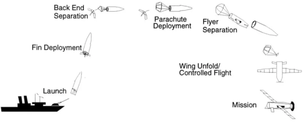
The mission profile of the WASP (Figure 1-2) presents a unique challenge to the design of a roll control actuation scheme. The size constraint of the artillery shell prompted the use of segmented wings in order to efficiently package the flyer. The current WASP wing calls for a carbon fiber wing 0.62 m in span with a midspan hinge located 0.3 m from the wing tip.
Several different actuation schemes could be implemented in order to provide adequate roll control for the WASP flier over its mission profile. The conventional approach would be the implementation of ailerons on the outboard segment of the wings. The initial design of
Back End _xL - I P achut SeparationA1 Parachute Deployment Fin Deployment Wing U Control Launch Flyer Separation nfold/ led Flight Mission
Figure 1-2: WASP mission profile.
the control surfaces called for the use of conventional aileron surfaces with a chord of 15.24 mm and a span of 254 mm. The basic characteristics are summarized in Table 1.1.
Table 1.1: Aileron characteristics
Chord 15.24 mm
Length(2x) 254 mm
Deflection range
+/-
15 degrees Max torque 1.36 N-rn Max Roll Rate 203 deg/sTraditionally, these control surfaces are actuated with discrete servos. The servos are typically connected to the surfaces by way of linkages and bearings. The initial design of the ailerons was intended as a stopgap measure and could not be implemented in the final vehicle. The small size of WASP increases the dynamic frequencies of the vehicle, exceeding the bandwidth of discrete servo-actuators. In addition, the actuation mechanism for this scheme called for the placement of the actuators outboard on the wing. This location would interfere with the folding mechanism as well as incur a drag penalty on the aerodynamics of the flyer. It was proposed to place the actuators inside the vehicle fuselage while running linkage arms outboard to the control surfaces. However, this would require the linkages to traverse an open gap across the hinge when the vehicle is stowed. It was also believed that the high g-loads experienced by the vehicle during launch would cause the required bearings and linkages to fail. Consequently, an alternate actuation scheme for these surfaces was
necessary.
The second approach to implement roll control has its origins as far back as the Wright flier. The wings of the WASP would be actively warped in flight. This scheme would allow for controlling the lift differentially between the two wings by locally changing the angle of attack, and consequently the lift. However, unlike the Wright flier, the WASP wing cannot use cables and pulleys to twist the wing. The midspan hinge as well as the high-g launch environment present a challenge to the implementation of this control method.
The third major approach involves the use of a spoiler concept. By actuating the spoiler, lift may be reduced locally on one of the wings. Consequently a net roll moment may be achieved providing suitable control for the vehicle. Two spoiler concepts were examined. The first concept was a discrete control surface located on the aft section of the wing that would disrupt the air flow over the foil. However, this configuration faces many of the same issues that a discrete aileron surface does regarding actuation mechanisms. The second design for the spoiler calls for the actuation of apertures to allow for air to flow through the body of the wing. This would nullify the pressure difference over the foil section resulting in a decrease
in lift.
1.3
Present Work
Active materials, particularly piezoelectric ones, present a possible solution to the challenges facing the above actuation schemes. Their small size and high bandwidth are ideally suited, allowing them to be packaged within the primary structure of the wing, g-hardening the actuator. This location for the actuators also eliminates linkages and bearings that may fail under the initial launch load as well as eliminate any drag penalty associated with having the actuators in the free stream flow. Incorporating active materials within the structure allows them to be used as primary structural elements resulting in an overall savings in weight.
This thesis will examine the implementation of active materials as a roll control mech-anism in the WASP vehicle. To accomplish this, models were constructed and experiments carried out to demonstrate the feasibility of active materials in a composite structure. ter 2 discusses previous research in the use of active materials in aerospace structures.
Chap-ter 3 discusses the analytical procedures including structural, aerodynamic, and aeroelastic modelling of the wing. Chapter 4 details the fabrication of the composite structure and the integration of the active materials. Chapter 5 describes the experimental setups including electromechanical testing. This chapter also discusses the test results and evaluates the ac-curacy of the modelling. Chapter 6 summarizes the conclusions arrived from this study as well as recommendations to for future work.
Chapter 2
Preliminary Actuation Mechanisms
Study
This chapter discusses preliminary studies into the use of active materials as a means of controlling the aerodynamics of a vehicle.
2.1
Performance Requirements
The target aerodynamic performance for the WASP vehicle was set by the Draper Laboratory [2]. A minimum roll rate of 30 deg/s was required. This value was determined based on the WASP mission profile that calls for loitering reconnaissance with no large roll angles. Based on the WASP characteristics, outlined in Table 2.1, this translates into a required roll torque of 0.428 N-m. A separate static roll torque goal was also set. This upper limit was designed to counter potential static roll torque sources that would act on the vehicle. These external roll sources would need to be corrected by the roll actuators in order to maintain the trim of the vehicle. The sources may be broken down into three major categories:
1. reaction to propeller torque
2. lateral gust disturbances
Table 2.1: WASP characteristics
WASP design velocity 26.8 m/s
Wing area (S,) 0.08 m2
Wing span (b) 1.27 m
WASP design dynamic pressure (q) 415.5 N/m 2
WASP damping coefficient (Cp) 0.75 WASP design minimum roll rate 30 deg/s Minimum roll torque (30 deg/s) 0.428 N-rn Roll torque goal (30 deg/s + roll offset) 1.769 N-rn
The contribution from each was determined to be 0.60 N-m, 0.27 N-m, and 0.47 N-rn respectively [2]. These values were obtained based on assumptions for the cruise power and propeller RPM as well as a maximum offset of 0.50 between wings and a maximum side slip disturbance of 100. The effect of these sources results in a maximum roll torque goal of 1.769 N-m. Aerodynamic stability requirements also exist. In order to maintain the stability of the vehicle, the static bending deflection of the wings under steady load should not exceed
13'. This corresponds to a tip deflection of 3.05 cm. The flutter boundary of the vehicle was also set to 1.2-VNE (velocity never exceed) =(1.2)(40.23 m/s)=48.28 m/s. This speed was determined based on the cruise velocity of the vehicle as well as the requirement that stability be maintained through a 13.41 m/s gust.
2.2
Discrete Control Surfaces
Primarily, three types of actuation schemes were examined using active materials embedded within the primary structure. The first method calls for the use of active materials to actuate a discrete control surface. The basic mechanism would entail the use of a piezoelectric bender or a mechanically amplified piezoelectric stack to actuate an aileron. Piezoelectric materials exhibit coupling between electrical and mechanical behavior. The application of an electric field to the material will cause a mechanical deformation. Conversely, applied deformation will result in the flow of charge through the material. The actuator would be mounted internal to the wing structure and would connect to the control surface directly. The location
of the actuator as well as the minimization of linkages makes this configuration naturally g-hardened. In addition, by placing the actuators within the primary wing structure, the wing would be able to fold completely allowing WASP to be packaged within the geometric constraints of the delivery vehicle.
2.2.1
Piezoelectric Benders
Piezoelectric benders have been used in controlling vibrations in helicopter rotor blades via a discrete flap [3]. Bench tests by Hall and Prechtl [4] have demonstrated flap deflections up to
11.50 under no load conditions. Analysis indicated that under load, the maximum deflection would be 6.7'. The piezoelectric bender actuator consists of a multilayered piezoelectric sheets bonded to a very thin metal shim (Brass, Aluminum). Equal but opposite fields are applied to the piezoelectric sheets on either side of the shim resulting in a pure bending moment. The resulting tip displacement is mechanically amplified to provide actuation for the flap. The piezoelectric bender actuator has the advantage of being simple to implement, however, the amount of control authority scales with the length of the actuator.
Figure 2-1: Piezoelectric bender
2.2.2
X-frame Actuator
To overcome the limitations of the simple bender actuator, different amplification schemes have been presented in literature [5-10]. Prechtl and Hall [11] have developed a high efficiency discrete servo-flap actuator. The X-frame actuator has demonstrated a mass efficiency be-tween 18% and 31% with a mechanical efficiency bebe-tween 38% and 50%. This scheme relies on the use of a non-active frame mechanism for amplifying the piezoelectric stack motion.
The X-frame consists of two piezoelectric stacks simultaneously actuating against two steel
frames. A roller pin is situated between the two frames allowing for relative rotation of the frames. The small angle of the frames relative to the stack axis results in a geometric stroke amplification of approximately 15. A compressive pre-stress is required to maintain contact between the frame and the stack. This is achieved by placing a tensile load along the load path of the actuator. In practical applications this was accomplished via a spring connected between the actuator and the flap [11].
Figure 2-2: X-frame actuator (Source: MIT AMSL web site).
Additional work has been conducted by Hall and Tzianetopoulou [12] to further refine this actuation scheme. The double X-frame actuator incorporates a number of design innovations over the original X-frame design. The volume of active material within the actuator has been increased. The pre-stress of the actuator stacks are applied internally. This avoids the disadvantage of the original X-frame causing a hard-over deflection of the flap in case of actuator failure.
The X-frame could be mechanically coupled to actuate an aileron surface in a similar fashion as the piezo-bender. The X-frame could also be used to actuate a spoileron concept (Figure 2-3). This concept recovers approximately 60% to 70% of the effectiveness of an aileron [13], while being relatively less complex mechanically. The actuator is well suited for this configuration. The X-frame would be situated at the hinge point. At this location, the required actuation is one that is high force with a small stroke, ideal for piezoceramic materials.
X-frame Actuator
Figure 2-3: Spoileron configuration.
2.3
Distributed Actuation
The second actuation scheme involves the use of distributed actuators. Distributed actua-tion follows two distinct paths. The first involves the use of sheets of piezoelectric material to actuate the aerodynamic surface. The work of Bernhard and Chopra [14] uses a dis-tributed actuation scheme to actuate a discrete control surface. The tips of a segmented rotor blade are actively pitched via a piezo-driven bending-torsion coupled beam. Piezo ele-ments mounted on the upper and lower surface of the beam are actuated in a similar manner of the piezo-bender to produce spanwise bending in the beam. The structural bend-twist couple of the beam results in an induced twist which is used to pitch the blade tips of the rotor. One distinct advantage exists in this system compared to a piezo-bender is that the entire wing span can be used for actuation. Since the actuation stroke scales with length, much larger actuations may be achieved without mechanical amplification. This system, however, demonstrates poor energy efficiency inherent in elastically coupled systems. Pre-liminary performance of a Mach-scale blade indicates blade-tip pitch deflections of 1.750. This performance comes at the cost of a significant weight penalty.
Work by Lazarus and Crawley [15, 16] and Nam and Kim [17] focused on the use of distributed piezoelectric wafer actuators as a means of flutter suppression of a composite lifting surface. Similarly, Ehlers and Weisshaar [18] studied the use of embedded piezoelectric actuators to change wing lift and divergence dynamic pressure by deforming the shape of the wing.
The second path of distributed actuation involves the use of Piezoelectric Fiber Compos-ites (PFC) [19]. Unlike traditional piezoelectric actuators that rely on piezoelectric wafers, this material combines fine ceramic fibers in a soft matrix to provide load mechanisms that
increase tolerance to damage by providing a load path around fiber cracks. This represents an improvement over ceramic wafer based actuators that are subject to macroscopic damage resulting from cracks in the material.
An example of PFC are Active Fiber Composites (AFC) [19]. AFCs are used with an interdigitated electrode pattern (Figure 2-4). This pattern orients the electrical field along the length of the fiber taking advantage of the directional actuation properties of the material (Figure 2-5). Application of an electric field causes in-plane actuation in the direction of the fibers.
Z
Figure 2-4: Active Fiber Composite
Electrodes
-
Poling
+-_ _Direction
Figure 2-5: Schematic representation of electric field in the fibers.
Extensive work has been done by Bent and Hagood [19] on the effectiveness of the in-terdigitated electrode pattern over standard Piezoelectric Fiber Composites. Values of free strain constants show a fivefold increase of AFC over PFC. When these materials are oriented at a ±45' to the blade span, they may be actuated to produce a pure twisting moment. The moment causes the lifting surface to twist affecting the overall lift distribution. These high strain actuators have been used extensively in the development of integrally-twist helicopter rotors.
MIT and NASA have built an integrally actuated rotor blade known as the Active Twist Rotor (ATR) [20]. The project successfully demonstrated the feasibility of using AFC as a means of actuation to achieve independent blade control on a helicopter rotor system. A twist rate of 1.50/m was achieved during forward flight tests at NASA Transonic Dynamics Tunnel [21].
2.4
Slotted Spoileron
A third actuation scheme was also examined. The method called for opening and closing small ports through the thickness of the wing. By controlling the flow of air through the cross-section, the pressure differential across the airfoil may be locally nullified, resulting in a decrease in lift. By actuating these ports differentially between the two wings, a net rolling moment may be produced. The concept was tested experimentally and the results are presented in detail in Appendix A.
2.5
Actuator Selection
Discrete actuation schemes and the slotted wing concept were not pursued further in this thesis. The lack of an applicable actuator in the slotted wing concept prohibited the im-plementation of a flight capable roll mechanism. Regarding the discrete actuators, research in the literature has demonstrated the successful implementation of these systems and con-sequently, the main issue for this study would be that of packaging the actuators within the wing. In addition, these actuation schemes still rely on mechanical linkages to join the actuator to the flap. Consequently, they have the potential for failing during the high-g launch environment. The relative high cost of the actuators also made their use prohibitive. Current cost of a X-frame actuator is estimated at approximately $10,000/actuator [22]. Finally, Koratkar and Chopra [3] have also shown that a major source of performance degra-dation for this type of actuation scheme is friction created at the blade flap interface. On the other hand, distributed actuation presents itself as an efficient and viable option for use in the WASP-class wing. The high bandwidth of piezoelectric-embedded actuators enables
robust effective control of the vehicle. Additionally, by integrating the actuators to the pri-mary structure, discrete servos, linkages, and bearings are no longer necessary resulting in a savings in weight and mechanical complexity. The relatively high strain rates exhibited by AFC packs as well as their ability to be easily incorporated within the structural layup of the wing makes them the most promising actuation scheme for implementing roll control for a WASP-class vehicle.
Chapter 3
Analysis of the Integral Twist
Concept
This chapter outlines the analytical procedures used to optimally design a WASP-class wing for use with an integral twist actuation scheme. Aerodynamic modelling was conducted to determine the wing twist needed to meet the given performance requirements. A static structural model of the wing was constructed and validated to optimize the layup in order to achieve the desired twist rate using AFC packs. The aeroelastic response of the wing was studied. MSC/NASTRAN was chosen for the analyses for its wide range of toolboxes. This range allowed for the study of the twist, aeroelastic, and the inertial loading within a single model.
3.1
Aerodynamic Analysis
A baseline model of the WASP was constructed in the Athena Vortex Lattice (AVL) [23]. The coordinate points of the foil cross-section were input and a constant cross-section wing was assumed. Initial analysis was conducted assuming a constant twist rate. A roll torque coefficient was derived by normalizing the required roll torques by the parameter q- S- b where
q is the dynamic pressure, S the wing area and b the wing span. Based on the requirements,
the worst roll torque condition.
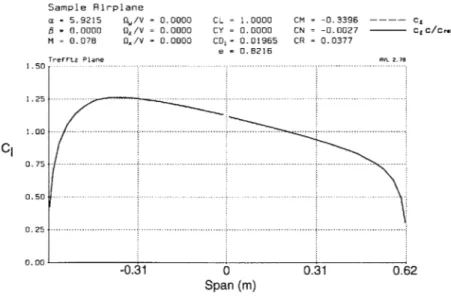
Initial results from AVL indicated that a tip twist angle of 0.60 (based on a linear twist distribution along the wing span) was necessary to satisfy the minimum roll torque require-ment. This translates into a twist rate of 0.95 deg/m. For the roll torque goal, a tip twist angle of 2.4' was determined with a corresponding twist rate of 3.87 deg/m. These values were calculated using the assumption that the wings would be actuated asymmetrically, i.e., one wing would twist up at an angle of 2.4', while the opposite wing would twist down 2.4'. The differential aerodynamic load on the wings shown in Figure 3-1 contributes to the roll moment on the vehicle.
Sample Airplane a - 5.9215 Og/V = 0.0000 B = 0.0000 oz/V = 0.0000 M = 0.078 Qx/V = 0.0000 Treftz Plane I1O.50...%... 1.25 1.00 0.75 0.50 0.25 0.00 CL = 1.0000 CM = CY = 0.0000 CN = CD,- 0.01965 CR = e = 0.8216 Span (m)
Figure 3-1: Treftz plane from AVL modelling.
Once the required twist angles were determined, an appropriate structural model could determine the optimal placement and number of the individual actuators as well as the structural layup of the composite wing.
-0.3396
-0.0027
0.0377
3.2
Structural Analysis
A finite element model of the wing with integral anisotropic piezoelectric actuators was developed to analyze the twisting of the wing. The baseline WASP layup was initially considered [24].
[+/-45
2/0
5]
~OC
[+/-452/0 21s
[+/-45/02]s
Figure 3-2: Base WASP layout and layup
The original wing design called for a taper in chord as well as thickness as shown in Figure 3-2. The layup was uniform along the lower surface of the wing [±45/02],. The upper surface of the wing tapered from a base layup of [±452/05], to [±452/02)s at the tip. The geometry was eventually changed in favor of a wing with constant cross-section along the span. The switch to this new configuration proved to be beneficial to the integral actuation scheme. The additional chord length allowed for more area to be covered with active materials, increasing the control authority of the wing.
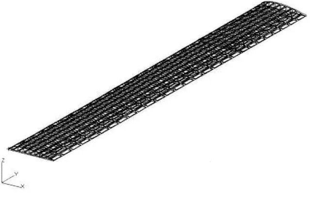
The initial model was comprised of an airfoil shell discretized into 9 spanwise segments (Figure 3-3). The discretization was included to allow for the spanwise taper in thickness that was present in the initial WASP layup. The chordwise taper in thickness was not
Figure 3-3: Base WASP finite element model
3.2.1
Equivalent Thermal Load
The piezoelectric effect of the AFC patches was modelled using an equivalent thermal load. The induced free strain of the piezoceramic material is assumed to behave linearly and proportionally to the applied electric field, and is given by
633 = d3 3
E
(3.1)where E is the applied electric field and d33 is the piezoelectric coefficient in the poling direction. The linearity of this relationship can be properly modelled in NASTRAN by applying an equivalent thermal load. Once the free strain of the actuators is known, a value for the coefficient of thermal expansion, a, can be input for the AFC material to model d33 and a thermal load, AT, applied to simulate the applied electric field.
633 =d33 -
E
~a -AT
(3.2)In this equation a is one of the anisotropic coefficients of thermal expansion. The direction of the coefficient is oriented along the length of the fiber. This ensures that the equivalent thermal load applies the strain in the same direction as the AFC actuators.
3.2.2
Twist Model
In order to determine the feasibility of the integral twist configuration, a baseline case was first considered to determine a reference twist authority that would be provided by the AFC patches. Initially, the entire upper and lower surface of the wing was covered with a single layer of AFC material. The resultant tip twist angle was 0.15'. The baseline layup of the original wing was extremely stiff in both torsion and bending. Without compromising any of the wing performance requirements, the off-axis plies were removed to reduce the torsional stiffness. A resultant tip twist angle of 1.35' was obtained. These results indicated that a feasible design exists that satisfies the desired actuation range of the wing. From this point, the layup of the wing could be optimized for roll performance while remaining within the flutter and static deflection boundaries outlined from aerodynamic analyses.
The model was then refined to accurately model the new geometry of the wing planform as well as the geometric shape of the actuators. The actuators chosen for this project were similar to the ones used by Schmidt [25] and Wickramasinghe [26] in support to the DARPA/Boeing/MIT Active Helicopter Rotor Program. This was done in order to save time as well as additional cost associated with customizing the actuators to the WASP wing. As a result, the actuators were not ideally sized for this application. The geometry of the actuators are shown in Figure 3-4.
16.4 c
4.6 cm
Li
Figure 3-4: Active Fiber Composite patch geometry
Due to the length of the actuators, only six could be placed on the wing (Figure 3-5), three on the upper and another three on the lower surfaces. This configuration resulted in a gap of approximately 14.6 cm where there would be no active material. Studies were conducted in both AVL as well as NASTRAN to determine whether the actuators should be placed more outboard or inboard on the wing in order to maximize the roll moment produced (Figure 3-6). Working with a base layup of three uni-directional 00 plies, the two actuator
0.49 m
0.072m
0.62 m
Figure 3-5: Spanwise actuator placement
placements were examined. The placement of the actuators inboard assumes that the wing will remain at a constant twist angle from the end of the actuator packs out to the wing tip. In both cases, the placement of the midspan hinge was not taken into account. The analysis assumes that the hinge would act as a rigid body, transmitting the twist angle between the two segments of the wing. The results are summarized in Table 3.1
Table 3.1: Actuator placement results
Location Tip Twist C,
Inboard t1.180 0.0175 Outboard
±
1.04' 0.0103 R oo i In boar d Out boaor d } 0.072 m 0.54 m 0.62 mFigure 3-6: Actuator placement options
Placement of the actuators inboard represents an overall improvement in performance for a given number of actuators and power of 70%.
The AFC actuators were placed one layer deep from the surface of the composite. This was done in an attempt to maximize the applied torque generated by the AFC by maximizing
the moment arm from the center of the foil while still having a layer of composite material protecting them from the external environment.
The resulting model consisted of 522 nodes and 756 elements (Figure 3-7). A total of 504 shell elements (QUAD 4) were used to model the composite structure including the AFC actuators. A combination of solid elements were used to model the core of the wing using 56 wedge elements near the leading and trailing edges with 196 tetrahedron elements for the center section of the core.
Figure 3-7: Finite element model of the active WASP wing
The AFC piezoelectric properties were input as coefficients of thermal expansion. The values of the ds3 were normalized along with the applied thermal load to produce an
equiva-lent 1000 pE. Only the AFC material was given a non-zero thermal coefficient. This ensures that no other material would be affected by the application of the thermal load. The com-posite material used was AS4/3501-6 comcom-posite system. The material properties for the AFC and the AS4/3501-6 are outlined in Table 3.2.
Table 3.2: Material properties of AS4/3501-6 composite system and AFC actuators
Property AS4/3501-6 AFC
EL 143 GPa 20 GPa ET 9.81 GPa 14.5 GPa 1 ILT
0.3
0.21
GLT5.58 GPa
4 GPa
thickness 0.127 mm 0.3429 mm density 1514 kg/m 3 4096 kg/m 3of its high temperature properties allowing it to be safely used in the autoclave during the fabrication process. Several different grades of Rohacell were examined to determine the lightest foam that would ensure the correct aerodynamic shape. The primary function of the foam core is to provide the proper back pressure during fabrication to ensure the composite material conforms to the shape of the mold. Rohacell 31 was selected experimentally for the core material. The mechanical properties of Rohacell 31 are outlined in Table 3.3.
Table 3.3: Material properties of Rohacell 31
Property Rohacell 31
E 36 MPa
G 14 GPa
density 30 kg/m3
The model was constrained at the root with a clamped boundary condition. A uniform thermal load was applied to the structure and the corresponding deflections were measured. In order to determine the twist angle, two nodes were selected at the tip of the wing. The difference between the leading and trailing edge deflections at the wing tip was measured from NASTRAN. This value was used to compute the twist angle at the tip of the wing. The chord length of the wing remains constant during actuation.
3.2.3
Modelling Validation
In order to ensure that the methodology used during the modelling was accurate, several test cases were run to compare with different analysis codes. The Active Twist Rotor blade described in Ref [20] was modelled in NASTRAN. The blade consisted of a 1-m long uniform beam with a NACA 0012 cross section of 0.11-m chord. The rotor was discretized into five regions in NASTRAN. The fairing, web, and nose were modelled separately along with the active regions along the upper and lower surfaces (Figure 3-8). The core of the rotor was not modelled as it was not included in the analysis conducted in [20]. The analysis used a two-cell thin-walled closed-section composite beam with anisotropic plies embedded in it. Preliminary results determined the twist rate for the ATR is 1.80/m. Analysis conducted in NASTRAN yielded a rate of 1.72'/m. This corresponds to an error of approximately 4.6%.
Active Region Wrap Joint Region Nose E-Glass 0/+90
E Glass 0/+90 AFC +45 Plies of Active
S-Glass 0 E-Glass +45/-45 Region +
E-Glass +45/-45 AFC -45 Web +
E-Glass 0/+90 E-Glass 0/+90 Fairing
Fairing -0.910.181 \ E-Glass 0/+90 0.476 1.88 E-Glass 0/+90 E-Gla ss 0/+90 - 4.24 (Unit:inch)
Figure 3-8: ATR Cross-section and layup (reproduced from [20], p. 106)
Additional analysis was conducted with an active composite box beam. Two box beams were modelled in VABS-A by Ortega-Morales and Cesnik [27]. Variational Asymptotical Beam Sectional Analysis (VABS-A) is a cross sectional analysis tool that calculates the beam stiffness and actuation constants for a cross section with arbitrary geometry made of anisotropic material. These beams consisted of a square cross section of 25-mm sides. The layups of the individual beams is shown in Figures 3-9 and 3-10.
25 mm
Figure 3-9: Geometry and material of box Figure 3-10: Geometry and material of box
beam BB1 beam BB2.
The beams were modelled in NASTRAN and the results compared. A predicted twist rate of 1.87'/m was obtained for the unidirectional beam compared with 1.760/m from VABS-A. This corresponds to an error of 6.23%. In the second case, a value of 0.737'/m was calculated compared to 0.814'/m from VABS-A. This corresponds to -9.35% difference. Based on the good correlation between two very distinct methods of calculating the actuation results, the NASTRAN model was deemed appropriate and validated for the present study.
3.2.4
Buckling Model
A nonlinear static analysis was also conducted to determine the effect of the initial launch acceleration on the redesigned layup. In the stowed configuration, the wing is folded and supported from a hinge at the root as shown in Figure 3-11. The outboard section is folded such that the mid span hinge is located towards the tail of the flyer, with the wing tip being on level with the root hinge. This results in the outboard segment of the wing being supported solely at the mid span hinge, leading to a compressive load during launch. The initial acceleration loads were provided by Draper Laboratory based on previous gun launch data. The specifications called for the wing to be able to survive an initial setback load of
16,000 g.
I
F
Tail
Wing
45deg
Hinge
Nose
Figure 3-11: Stowed configuration of WASP (courtesy of Draper Laboratory) A half-wing model was constructed in NASTRAN to simulate the outboard segment only as shown in Figure 3-12. This model was constructed in a similar fashion as the twist model. The root of the wing was cantilevered and an inertial load of 16,000 g applied to the structure. A failure model was implemented to ensure that the applied loads did not exceed the allowable levels for interlaminar shear stresses as well as the maximum allowable strain for the composite materials. In the case of the AFC layers, the allowable strain levels corre-sponded to the maximum strain the AFC fibers can withstand without depoling. Depoling the fibers would render the AFC actuators useless. This would constitute a failure of the structure despite the maintained structural integrity of the wing. Results from NASTRAN indicated that the wing would survive the launch with minimal out of plane deflections. A maximum value of 0.1956 mm was calculated for the out of plane deflection with a corre-sponding compression of 0.08 mm. This corresponds to a maximum strain of 600 pE while the allowable strains for the AFC fibers is 2500 pe.
Figure 3-12: Buckling model of wing
3.3
Aeroelastic Analysis
Once the placement of the actuators on the wing was determined, and the methodology validated, the laminate was modified in an attempt to minimize the overall stiffness and weight. Off-axis plies were removed from the upper and lower surfaces in an attempt to reduce the torsional stiffness of the wing. Once all the off-axis plies were removed, it was determined that the wing was still excessively stiff in torsion and bending. As a result, 0' were removed in an attempt to further reduce the overall stiffness. The number of plies that could safely be removed from the layup ended up being limited by the aeroelastic requirements on the flyer. These requirements set a limit on the flutter speed as well as the maximum induced dihedral of the wings under steady aerodynamic loading.
To determine the aeroelastic performance of the wing, a model was created in NASTRAN using the aeroelastics package. The aerodynamic model utilizes a flat plate doublet-lattice method. The aerodynamics are coupled to the structure through spline elements. These spline elements serve to transmit load and deflection values between the aerodynamic plate
and the structural mesh. The flutter analysis was performed using the p-k flutter method. A modified Givens method was used to extract the eigenvalues and corresponding eigenvectors from the system.
Successive off-axis plies were removed and the flutter speed of the wing calculated. The finalized design consisted of a uniform layup with two uni-directional 0' plies on both the upper and lower surfaces. The flutter speed for this configuration was calculated to be 75 m/s. Decreasing the thickness of the layup beyond this point resulted in a flutter speed that was within the flight envelope of the WASP.
This configuration was then loaded statically under cruise conditions to determine the steady state induced dihedral of the wings. The wings were also subjected to an actuation load in order to determine the worst case steady state deflection. Figure 3-13 summarizes the results. For the steady cruise case, the maximum deflection is 0.93 cm. For the actuated case, the maximum value is 1.5 cm. This increase is due to the increased pitch of the wing as well as the resultant increase in the aerodynamic forces. Both these values are well below the 3.05 cm prescribed limit.
3.5
Maximum design limit
3,
2.5
C
0
D .5
Steady Cruise Steady Cruise w/ Actuation
3.4
Final Design
The final design for the WASP wing obtained from the analysis consisted of a uniform cross-section with no taper in either thickness or chord. The cross-cross-section is represented in Figure 3-14. The design consisted of a uniform layup with two uni-directional 0' plies on both the upper and lower surfaces.
Rohacell 31 was selected as the material for the core of the wing. 6 actuators were placed along the span of the wing, three actuators on either surface. The actuators were placed inboard starting at the root leaving a region of approximately 14.6 cm with no actuation at the tip of the wing as shown in Figure 3-15. The main characteristics of the wing are summarized in Table 3.4
Table 3.4: Results of final design
Property
Tip twist Angle
(+)
Flutter Speed Induced Dihedral Final Design 1.550 75 m/s 1.5 cm Requirement 0.590-2.410 > 54 m/s < 3.0 cm Active region AS4/3501-6 0 AFC 45 AS4/3501-6 0 4.6 cm | 2.54 cm | 7.2 cm Figure 3-14: Active region AS4/3501-6 0 AFC -45 AS4/3501-6 0WASP wing final cross-sectional layup
0.54 m
062 m
Figure 3-15: WASP wing actuator placement
Chapter 4
Fabrication
This chapter describes the fabrication of the active wing used to demonstrate the wing warp-ing concept. The prototype wwarp-ing was manufactured accordwarp-ing to the final design described in Chapter 3.
4.1
Wing Mold
The redesigned planform and manufacturing procedure of the wing required the fabrication of a new mold. The previous design of the WASP wing involved a wet layup. The individual surfaces of the wing were manufactured and then bonded together with a secondary cure. For the new design, the upper and lower surfaces were co-cured resulting in a solid cross-section. The new design called for a two piece closed mold as shown in Figure 4-1. The mold was oversized to allow for an additional 3.8-cm of clearance along the length of the wing. This additional length provided a clamping surface for the wing to be mounted. The mold was split along the lower surface of the foil. The aerodynamic shape of the foil was machined into a 2.54-cm thick piece of aluminum and capped with two aluminum end plates. The second piece of the mold was machined flat to ensure good surface finish on the composite. Clearance holes were drilled every 7.62-cm along the length on both sides of the mold to allow the two halves to be bolted together. An opening was also cut through one of the end caps. This allowed for the AFC wiring to be passed to the outside of the mold during cure.
The wires were wrapped in non-porous teflon. This ensured that no excess resin would coat the wires. Fabrication of the wing mold was carried out at the MIT Central Machine Shop.
Figure 4-1: Wing mold
4.2
Foam Cores
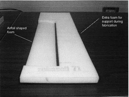
The cores of the wings consisted of Rohacell 31 foam. The core was shaped to provide back pressure for the surrounding composite during the cure. The foam cores for the wing needed to be machined to the aerodynamic shape of the airfoil. As a base point, the shape of the mold was used. The ply and AFC thicknesses were then subtracted from this shape. An additional 0.254-mm to 0.381-mm was then added to the thickness of the foam cores. This was done in order to provide sufficient back pressure on the composite laminates during the cure cycle, ensuring the correct outer mold lines. Due to the high temperature properties of Rohacell, a hot wire cutter could not be used for fabrication. Once the correct shape was calculated for the cores, the drawing was imported into Mastercam in order to generate a tool path. The foam cores were then machined in 40.6-cm segments on a 3-axis CNC milling machine. An example of the final product is shown in Figure 4-2.
Figure 4-2: Foam core
4.3
Active Elements
4.3.1
Flexible Circuit
A flexible circuit was required in order to achieve a low volume/low profile solution to the
challenge of distributing power to the AFC packs. The circuit consists of multiple parallel lines of wiring embedded in a thermoplastic material with an insulating cover of kapton. The gauge of the wires was selected based on the smallest possible diameter capable of carrying the current required to drive the individual packs. A 34-gauge magnet wire was chosen. This wire has a diameter of 0.1601 mm and has a normal current rating of 79.5 mA. The spacing of the individual wires was designed to ensure that the high voltages would not cause arcing between adjacent lines, resulting in a short circuit.
The outline of the the AFC patches was laid out on a board (Figure 4-3). Traces were then drawn to represent the wire spacing within the flexible circuit. For ease of fabrication, the wires were spaced 0.3175 cm (0.125") apart. This distance is well above the required spacing based on the dielectric strength of the thermoplastic (120,000 V/mm). A sheet of 0.127 mm Ultem was then placed on the board and secured with nails. The nails provided a guide for placing the individual wires within the circuit. Once all six lines were laid out
and pulled tight, they were secured using kapton tape. The purpose of the tape was twofold. It provided a means of securing the lines and ensuring that they remained parallel along the length of the circuit. The tape also provided an additional layer of electrical insulation. This would help to ensure that the circuit would not fail by arcing through the thickness of the thermoplastic and travelling through the conductive carbon on either side. The circuit was then flipped over, and an additional layer of Ultem and kapton tape were applied. This additional layer of Ultem provides sufficient thickness so that the wires end up completely embedded in the thermoplastic.
Flexible Circuit
Figure 4-3: Flexible circuit template
7 4cm 8.9cm 7 4cm 8.9cm 7.4cm
.3175cm line spacing
66cm
Figure 4-4: Flexible circuit drawing
This fabrication technique was carried out using a small scale specimen. The specimens were laid out and fabricated using a hot press. Once the circuit was cured, it was sandwiched between two pieces of carbon and cured using the identical cycle that would be applied to the wings. The circuit was then tested by applying a voltage across adjacent lines until they failed. Failure occurred at 4.9 kV. This is well above the operational limits expected.
The full scale circuits were then placed on a flat cure plate and sealed. The autoclave was required for the full scale because of the relatively small size of the hot press (35.6-mm x 35.6-mm). The high glass transition temperature of the thermoplastic (221 C) necessitated the use of non-porous teflon film instead of conventional vacuum bagging. Once sealed, the layup was placed in the autoclave and heated until the temperature of the plates reached
232'C. Once this temperature was reached, 206.8 kPa of pressure was applied to ensure that the two Ultem sheets were joined and that the wires were completely embedded.
4.3.2
Assembly
The circuits were then tested to ensure that they could provide the necessary power to the AFC patches without failure. Individual lines were hooked up to a power supply and a voltage of 4 kV applied. Once the circuits were tested, the AFC patches were laid out and the circuits connected. A final capacitance measurement was taken and compared with the results provided by the manufacturer: Continuum Control Corp., Billerica, Massachusetts. The results are summarized in Table 4.1.
Table 4.1: Actuator capacitance measurements
Serial
#
From manufacturer (nF) Measured (nF) locationS/N 001 7.98 8.23 Lower surface root
S/N 003 7.48 7.62 Upper surface root
S/N 004 8.48 8.67 Upper surface mid
S/N 005 8.49 8.57 Upper surface tip
S/N
007 9.16 9.37 Lower surface midS/N 008 9.16 9.24 Upper surface tip
The lengths of the individual leads on both the circuit as well as the AFC were trimmed to eliminate any excess. The circuit leads were then soldered to the tabs on the individual AFC actuators.
The electrical connections between the circuit and AFC patches were then mechanically isolated from the surrounding carbon. The solder joint was sandwiched between two pieces of kapton tape to electrically insulate the joint. In order to ensure that this configuration would sustain the applied electrical loads, voltage was applied to a wire sandwiched between grounded aluminum plates with kapton tape as a barrier. The voltage was steadily increased until the dielectric breakdown occurred at approximately 5 kV.
Figure 4-5: Circuit and actuators
4.4
Final Assembly
In preparation for curing, all surfaces of the blade mold were cleaned. Excess resin from previous cures was removed and the mold was coated with five coats of mold release. The releasing agent used was not in aerosol, but rather in liquid form. This prevents any pock-marks developing on the surface of the foil that may result from condensation of water on the surface of the mold.
Prior to assembly, the Rohacell foam cores were heated to 266'F for 24 hours. This was done to remove any moisture that may have been absorbed into the foam. Moisture has a plasticizer effect on Rohacell. The addition of moisture may result in loss of compressive strength as well as wrinkling of the foam cores.
Two sheets of AS4/3501-6 pre-preg were then cut. The dimensions of the sheet are 0.66 m x 0.1486 m with the 0' aligned with the long axis of the piece. The length of the outer contour of the airfoil was calculated using a MATLAB script (Appendix B). The first sheet of pre-preg is then laid out, aligning the edge of the material with the trailing edge of the foil. The material is then laid out along the curved surface of the mold. The AFC and the attached circuit are then laid in place, and the second sheet applied. At this stage, the foam cores are added and the innermost ply of pre-preg was wrapped around them. This ensures
that the leading edge of the wing is continuous. The second AFC group with the attached circuit is then laid out and the outer layer of carbon is wrapped around. The wiring for the circuits is passed through the end cap, and the mold is then closed and bolted. Pressure is applied to the mold to ensure the two halves are uniformly spaced. The fabrication steps are illustrated in Figures 4-6 through 4-10
The mold was then placed in the postcure oven and heated to 315'F. This lower temper-ature was required to ensure that the Rohacell cores did not exceed the heat deformation temperature. In order to ensure that the wing would be sufficiently cured, the mold was left at temperature for 3 hours. At the end of 3 hours, heat was removed and the oven was cooled at a rate of 5 /minute. This serves to avoid thermal shock in the composite which may produce cracks.
Once the wing was removed it was visually inspected to determine if the cure was success-ful. Initial observations showed a good surface finish over a majority of the wing. However, certain regions appeared to be low in resin content. In particular, these regions occurred surrounding the AFC packs, with the most severe instances occurring at the leading edge. A wrinkle in the surface finish was also detected at the leading edge. This wrinkle could be easily filled with epoxy, and consequently should not adversely affect the aerodynamic performance of the wing. The asymmetric location of the AFC packs also induced a pretwist in the wing. The pretwist tip angle was measured to be approximately 5.22'. These are shown in Figure 4-11.
Figure 4-6: Wing mold and actuators
Figure 4-7: Outer ply and upper surface actuators
Figure 4-9: Lower surface actuators

![Figure 3-8: ATR Cross-section and layup (reproduced from [20], p. 106)](https://thumb-eu.123doks.com/thumbv2/123doknet/13847875.444568/31.918.208.674.520.795/figure-atr-cross-section-layup-reproduced-p.webp)