HAL Id: tel-00669588
https://tel.archives-ouvertes.fr/tel-00669588
Submitted on 13 Feb 2012HAL is a multi-disciplinary open access
archive for the deposit and dissemination of sci-entific research documents, whether they are pub-lished or not. The documents may come from teaching and research institutions in France or abroad, or from public or private research centers.
L’archive ouverte pluridisciplinaire HAL, est destinée au dépôt et à la diffusion de documents scientifiques de niveau recherche, publiés ou non, émanant des établissements d’enseignement et de recherche français ou étrangers, des laboratoires publics ou privés.
Newton-Euler approach for bio-robotics locomotion
dynamics : from discrete to continuous systems
Shaukat Ali
To cite this version:
Shaukat Ali. Newton-Euler approach for bio-robotics locomotion dynamics : from discrete to con-tinuous systems. Automatic. Ecole des Mines de Nantes, 2011. English. �NNT : 2011EMNA0001�. �tel-00669588�
Shaukat ALI
DOCTRAL SCHOOL: STIM THESIS N° 2011EMNA0001Thesis submitted to obtain the Doctorate degree of the Ecole des Mines under the label of the Université Nantes, Angers, Le Mans
Discipline: Biomechanics and Bio-engineering
Defended on 20 December 2011
Newton-Euler Approach For
Bio-Robotics Locomotion
Dynamics: From Discrete To
Continuous Systems
Supervisor:
BOYER Frédéric, Professor, École des Mines de Nantes, Nantes, France Reviewers:
LASCHI Cecilia, Associate Professor, Scuola Superiore Sant’Anna, Pisa, Italy CHOSET Howie, Professor, Carnegie Mellon University, Pittsburgh, USA Examiners:
JAULIN Luc, Professor, Université de Bretagne Occidentale, Brest, France ROUCHON Pierre, Professor, Mines PariTech, Paris, France
KHALIL Wisama, Professor, Ecole Centrale de Nantes, Nantes, France
1
Abstract
This thesis proposes a general and unified methodological framework suitable for studying the locomotion of a wide range of robots, especially bio-inspired. The objective of this thesis is twofold. First, it contributes to the classification of locomotion robots by adopt-ing the mathematical tools developed by the American school of geometric mechanics. Secondly, by taking advantage of the recursive nature of the Newton-Euler formulation, it proposes numerous efficient tools in the form of computational algorithms capable of solving the external direct dynamics and the internal inverse dynamics of any locomotion robot considered as a mobile multi-body system. These generic tools can help the engi-neers or researchers in the design, control and motion planning of manipulators as well as locomotion robots with a large number of internal degrees of freedom. The efficient algorithms are proposed for discrete and continuous robots. These methodological tools are applied to numerous illustrative examples taken from the bio-inspired robotics such as snake-like robots, caterpillars, and others like snake-board, etc.
1
Contents
1 General Introduction 1
1.1 Motivations and Contents . . . 1
1.2 Organization of the Thesis . . . 3
2 Bio-inspired Locomotion Modeling: An Overview 5 2.1 Animal Locomotion . . . 5
2.2 Bioinspired Locomotion Robots . . . 9
2.3 Modeling of Bio-inspired Locomotion Systems: The Lagrangian Picture . . 16
2.4 Conclusions . . . 34
I
Discrete Systems: Mobile Multibody Systems
37
3 Locomotion Dynamics Algorithm of Mobile Multibody Systems 39 3.1 Description of a Mobile Multibody System . . . 413.2 Luh and Walker Manipulator Dynamics. . . 47
3.3 Overview of the Proposed Algorithm . . . 49
3.4 The Unconstrained Mobile Multibody System . . . 54
3.5 The Constrained Mobile Multibody System . . . 59
3.6 Kinematics of a Constrained Mobile Multibody System . . . 59
3.7 Dynamics of the Constrained Mobile Multibody System . . . 67
3.8 Computational Algorithm . . . 73
3.9 Conclusions . . . 77
4 Illustrative Examples of Mobile Multibody Systems 79 4.1 Satellite with Rotors: Unconstrained Case . . . 79
4.2 The Snakeboard: Under-Constrained Case . . . 83
4.3 Snake-like Robot: Fully-Constrained Case . . . 88
4.4 Mobile Manipulator: Fully-Actuated Case . . . 91
II
Continuum Systems: Hyper-Redundant Robots
97
5 Macro-Continuous Dynamic Modeling of Hyper-Redundant Robots 99
5.1 Modeling Approach of Hyper-Redundant Robots. . . 100
5.2 Beam Kinematics and Hyper-Redundant Robots . . . 105
5.3 Continuous Models of Hyper-Redundant Robots . . . 107
5.4 Dynamic Algorithm of Hyper-Redundant Robots . . . 112
5.5 Terrestrial Locomotion Model . . . 114
5.6 Conclusions . . . 122
6 Illustrative Examples of Hyper-Redundant Robots 123 6.1 Earthworm in 1D . . . 124
6.2 Climbing Inchworm in 2D . . . 133
6.3 2D Snake in Lateral Undulation . . . 140
6.4 3D Snake in Lateral Undulation . . . 149
6.5 Further Discussion: Application to Real Designs . . . 153
6.6 Conclusions . . . 155
7 General Discussion and Conclusions 157 7.1 Summary of the Thesis . . . 157
7.2 First Conclusive Discussion: Projective vs Distributive Approach. . . 158
7.3 Second Conclusive Discussion: Lagrangian vs Newton-Euler Modeling Ap-proach . . . 162
7.4 Perspectives . . . 164
8 Thesis Detailed R´esum´e in French 167 8.1 Introduction G´en´erale . . . 168
8.2 La locomotion bio-inspir´ee . . . 170
8.3 Probl`eme g´en´eral abord´e dans cette th`ese. . . 171
8.4 Introduction aux Syst`emes Multicorps Discrets. . . 173
8.5 Dynamique inverse r´ecursive des manipulateurs . . . 177
8.6 Aper¸cu de l’algorithme . . . 178
8.7 Les syst`emes multicorps mobiles non-contraints . . . 179
8.8 Les syst`emes multicorps mobiles contraints . . . 182
8.9 Examples illustratifs . . . 189
8.10 Introduction aux Robots Hyper-Redondants . . . 193
8.11 Notations et d´efinitions . . . 194
8.12 Cin´ematique de la poutre et des robots hyper-redondants . . . 195
8.13 Mod`ele continu des robots hyper-redondants . . . 196
8.15 Mod´elisation cin´ematique des contacts . . . 200
8.16 Algorithme dans le cas cin´ematique . . . 203
8.17 Exemples illustratifs . . . 205
8.18 Conclusions . . . 214
A Appendix A 217 A.1 Extension of the Luh and Walker Algorithm to Closed Loop Kinematics. . 217
A.2 Covariants . . . 218
A.3 3D Snake: Compatibility Condition . . . 219
B Fundamentals of Lie Group Theory 221 B.1 Lie Group . . . 221
B.2 Adjoint Operators. . . 223
B.3 Lie Group in 2D Space (G=SE(2)) . . . 224
1
List of Figures
2.1 Action-reaction principal of a locomotion system . . . 6
2.2 (a) Sandfish (Scincus scincus): a lizard that can swim in granular media such as sand; (b) microscopic view of shark skin . . . 7
2.3 Gecko: a lizard with adhesive setae on its feet . . . 7
2.4 How snakes move . . . 8
2.5 The swimming robots of RoboTuna by MIT: (a) The ”Charlie-I”; (b) The ”RoboTuna-II”. . . 10
2.6 The pioneering snake-like robot ACM-III with passive castor wheels . . . . 11
2.7 ACM-R5 snake-like robot with passive wheels . . . 12
2.8 Snake-like robots designed by NTNU: (a) Wheeko with passive wheels; (b) Kulko with tactile sensors . . . 12
2.9 Uncle Sam: snake-like robot at CMU . . . 13
2.10 (a) Sandfish robot; (b) Stickybot-III. . . 14
2.11 Robotic arms: (a) CardioArm; (b) Elephant trunk-like manipulator . . . . 15
2.12 Octopus Arm robot bio-inspired from octopus . . . 15
2.13 Soft robot inspired from caterpillar . . . 16
2.14 Configuration space of a double pendulum: example maniflod . . . 17
2.15 Configuration space of a rigid body . . . 18
2.16 Configuration space as the principal fiber bundle. . . 19
2.17 Configuration space of a locomotion system: the principal fiber bundle . . 20
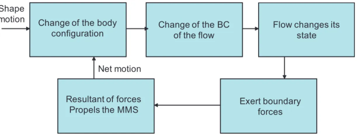
2.18 Flow chart of the recursive locomotion dynamics algorithm . . . 21
2.19 Problem of locomotion . . . 22
2.20 Connection between motions ( ˙r) on S and motions (η) on G (from [32]) . . 23
2.21 Fiber bundle: (a) principal fiber bundle G × S; (b) Tangent bundle T M of a manifold M . . . 23
2.22 (a) Gauss-Bonnet theorem illustrated on S2; (b) A cyclic change of shape produces a net displacement in G . . . 24
2.23 Mechanical connection: falling cat and satellite with rotors . . . 25
2.25 Example of fluid contact dynamics . . . 30
2.26 Under-constrained systems (a) Snakeboard (b) Trikke . . . 33
3.1 Tree-like structure of a mobile multibody system: (a) Manipulator; (b) Wheeled system . . . 42
3.2 Concept of isolated and composite body . . . 42
3.3 Axes of a wheel . . . 43
3.4 Types of unidirectional wheel . . . 44
3.5 Newton-Euler parametrization of a mobile multibody system . . . 46
3.6 Luh and Walker computational torque algorithm. . . 48
3.7 Wheeled mobile multibody system with passive wheels: (a) Two-axles mo-bile multibody system; (b) Three-axles momo-bile multibody system . . . 49
3.8 Scope of locomotion dynamics algorithm . . . 51
3.9 Flow chart of the recursive locomotion dynamics algorithm . . . 53
3.10 Execution of proposed algorithm in case of an unconstrained mobile multi-body system . . . 57
3.11 Execution of the general algorithm in mixed kinematic and dynamic case . 77 4.1 Satellite with rotors: (a) Outline sketch; (b) Tree-like structure . . . 80
4.2 Inertia rotors for re-orientation of satellite in space . . . 81
4.3 (a) Commercial snakeboard; (b) Robotic prototype of the commercial snake-board . . . 83
4.4 Snakeboard: (a) Outline sketch; (b) Tree-like structure . . . 83
4.5 Tree-like structure of snake-like robot . . . 88
4.6 Outline sketch of snake-like robot . . . 89
4.7 Motion of the head body So in the xy plane . . . 91
4.8 Joint torque τ10 . . . 92
4.9 All joint torques at t = 10 sec . . . 92
4.10 (a) Staubli manipulator mounted on a car like platform; (b) Top view of the platform, R2 = 0.42, D3 = R4 = 0.45 . . . 93
4.11 Top view of the car-like platform, l = 1.0, L = 0.5 . . . 94
4.12 (a) Torque τ1 for two different values of ξ; (b) Wheel torque for ξ = 1 . . . 95
5.1 Frames and parametrization of a hyper-redundant robot . . . 102
5.2 Representation of vector fields η(X) and ξ(X) . . . 104
5.3 General algorithm of hyper-redundant robots . . . 112
5.4 Execution of the general algorithm of a hyper-redundant robot . . . 114
5.5 (a) Locked anchorage; (b) sweeping anchorage . . . 116
5.7 (a) Reaction wrench on an anchored cross section; (b) Reaction wrench on
a cross section in annular contact . . . 119
5.8 Algorithm of a hyper-redundant robot with kinematic constraint model . . 120
5.9 Execution of kinematic algorithm of a hyper-redundant robot. . . 121
6.1 A natural earthworm . . . 124
6.2 (a) Initial reference configuration; (b) Deformed configuration with sweep-ing anchorage point C(t) . . . 125
6.3 A cylindrical cross section in three different forms. Aois the area of relaxed cross section . . . 126
6.4 Earthworm locomotion along x-axis . . . 131
6.5 (a) Time vs head position; (b) Time vs head velocity . . . 132
6.6 Internal control forces N(X) over the length with constant c . . . 133
6.7 With variable c(t): (a) Axial contact force Nc at X = C; (b) Internal control forces N(X) over the length of earthworm . . . 134
6.8 (a) Ω-shaped bending configuration of an inchworm; (b) Inchworm in un-structured environment . . . 135
6.9 Ω-shaped bending configuration of an inchworm . . . 136
6.10 Bilateral reaction forces at the anchorage point . . . 137
6.11 Climbing inchworm locomotion along vertical y-axis . . . 139
6.12 (a) Time vs head position; (b) Time vs head velocity . . . 139
6.13 (a) Vertical reaction force NcY at head; (b) Reaction torque CcZ at head . 140 6.14 Internal control torque over the length . . . 140
6.15 (a) Discrete Kirchhoff-snake; (b) Discrete Reissner-snake . . . 141
6.16 Bilateral nonholonomic constraint imposed on cross section X by cross sectional follower annular contact . . . 142
6.17 2D snake with cross sectional follower type annular contacts which imposes the lateral contact forces . . . 145
6.18 Curvature profile along the snake’s backbone . . . 147
6.19 2D snake straight line locomotion in xy plane . . . 148
6.20 2D snake turning locomotion in xy plane . . . 149
6.21 At t = 2.0s (a) Contact force (NcY) over the length; (b) Internal torque (CZ) over the length . . . 149
6.22 (a) Head turning locomotion; (b) Snapshots of snake 3D turning locomotion153 6.23 At t = 2.0s (a) Contact forces (NcY, NcZ) over the length; (b) Internal torques (CY, CZ) over the length. . . 154
6.24 Proposed design of a 3D snake: (left) cross-sectional view, (right) longitu-dinal view . . . 155
8.1 Structures arborescentes d’un syst`eme multicorps mobile: (a) un
manipu-lateur; (b) un syst`eme `a roues . . . 175
8.2 Syst`emes multicorps `a roues: (a) Syst`eme multicorps avec deux essieux; (b) Syst`eme multicorps avec three essieux . . . 179
8.3 Le Snakeboard . . . 189
8.4 Les trois premiers modules du robot serpent . . . 191
8.5 (a) le mouvement de So dans le plan xy; (b) couple articulaire τ10 . . . 192
8.6 (a) Ancrage verrouill´e; (b) Ancrage glissant. . . 201
8.7 Contact annulaire . . . 202
8.8 La locomotion du ver dans le plan xy . . . 207
8.9 Avec c variable: (a) les forces externes de reaction Nc; (b) les forces internes N . . . 207
8.10 La locomotion de la chenille dans le plan xy plane . . . 208
8.11 (a) Couple de reaction externe `a la tˆete; (b) les couples internes . . . 209
8.12 (a) Serpent-Kirchhoff discret; (b) Serpent-Reissner discret. . . 209
8.13 Profile de courbure du serpent . . . 212
8.14 Serpent 2D avec p contacts annulaires. . . 213
8.15 Le mouvement du serpent 2D avec le virage dans un plan xy . . . 214
1
List of Tables
3.1 Classification of mobile multibody system dynamics . . . 75
5.1 Actuated degrees of freedom vs Beam theory . . . 106
5.2 Internal degrees of freedom vs natural applications. . . 106
5.3 Contacts in terrestrial locomotion . . . 115
6.1 Reduction of 3D parameters to 1D parameters . . . 127
1
General Introduction
1.1 Motivations and Contents . . . 1
1.2 Organization of the Thesis . . . 3
1.1
Motivations and Contents
More or less deliberately, from its beginning, robotics took inspiration from nature to design its robots. Robots resembling to human arm were designed using discrete mech-anisms devoted to the manipulation tasks of industrial manufacturing processes. These discrete mechanisms consist of serial chains of rigid bodies connected by lumped degrees of freedom and are today included into the wider class of systems known as multibody systems. After manipulators, robots designers started to build mobile robots as wheeled platforms. When the environments become unstructured, legs are more adapted than wheels and mobile robotics oriented its investigations towards legged robots inspired from walking animals so opening consciously the way of bio-inspiration. With the passage of time, taking inspiration from the wide diversity of the animal kingdom, the researchers in this field started developing mechanisms with more and more internal degrees of freedom, hence introducing a new generation of robots called as hyper-redundant systems since they may be considered as having an infinite degree of redundancy with respect to the six dimensional task consisting of moving a rigid body in space. Even, nowadays, the robotics have entered into the era of soft robotics where the robots have no rigid bodies in their structure. In this case, the source of bio-inspiration is provided by soft animals, named as hydrostats, such as worms, caterpillars, octopus, etc. From the mechanist’s point of view these systems can be considered as continuous systems having an infinite number of degrees of freedom.
These increasing complexities of the design is in particular due to the diversification of lo-comotion modes involving more and more complex leaning media such as versatile grounds,
2 Chapter 1. General Introduction air, water, etc. Today, active researches in bionics allow us to progressively discover the subtle mechanisms that animals have discovered along evolution of species to improve their dynamic performances in terms of energetic consumption or manoeuvrability. As such lo-comotion systems become more and more complex, so do their mathematical models. Consequently, we need today efficient methodological tools that can help the roboticists in modeling, design, control, motion planning (gait generation, transit maneuvers), etc. In this regard, the dynamic models along with their associated algorithms are of great interest to researchers due to their active role in simulation, design and control. Keeping in view this growing interest, in this thesis we propose a unified methodological framework that is capable to address the problem of bio-inspired locomotion to a greater extent. More precisely, the aim of this thesis is two folds. Firstly, it contributes to the classification of lo-comotion robots. Secondly, it proposes new efficient tools for their dynamic computation. As regards the first objective, we will use mathematical tools introduced by the American school of geometric mechanics after Marsden [60, 49, 59]. Remarkably, these abstract tools will allow us to exhibit the common geometric structures shared by apparently very different locomotion ways as for instance snakes creeping and swimming at high Reynolds. As regards the second objective, starting from manipulators there are two major algorith-mic approaches to solve the problems of robots dynaalgorith-mics. The first approach is based on Lagrangian mechanics and leads to explicit formulations parameterized through a mini-mal set of generalized independent coordinates [92]. The second approach is based on the application of Newton’s laws and Euler’s theorem to each of the isolated bodies, and is consequently named Newton-Euler formulation [4]. Whether applied to the inverse dy-namics through the algorithm of Luh and Walker [115] or to the forward dynamics through the algorithm of Featherstone [40], Newton-Euler formulation leads to O(n) algorithms (where n is the number of bodies of the system). On the other hand, Lagrangian formu-lation leads to O(n) or O(n4) algorithms depending upon whether they are recursive (like
the Newton-Euler based algorithms) [54] or not [114, 58]. The Newton-Euler approach, once coupled with a symbolic customized code, gives the most optimized algorithms [64]. This advantage is crucial when we investigate some systems with large number of links and degrees of freedoms such as in case of hyper-redundant manipulators [52,100,25,72]. Moreover, Newton-Euler algorithms are particularly interesting when considering modular or reconfigurable robots [24] since, in this case, changing the topology of the system only changes the indexation of the bodies without compromising the structure of the algorithm. Despite these advantages, a general Newton-Euler based framework exists only for ma-nipulators, i.e. for multibody systems with a fixed base [40], while the most unified theory of dynamics of locomotion systems is based on the Lagrangian geometric mechanics on principal fiber bundles [87, 60, 76, 101]. As an asymptotic case, we will see that
hyper-1.2 Organization of the Thesis 3 redundant robot dynamics can be modeled by a continuous version of the Newton-Euler formulation with no Lagrangian counterpart in this case [13, 16]. In fact, the existing approaches used to model hyper-redundant robots can be categorized into two main sets depending on whether the robot is considered as a discrete multibody system with a large number of degrees of freedom [63, 78], or directly as a continuous deformable medium. In the first case, the modeling is facilitated by the fact that mathematical tools from usual discrete robotics are already available. On the other hand, adopting a continuous model from the beginning can greatly facilitate the formulation, analysis and resolution of the robotics problems related to manipulation [26, 83] and locomotion [52, 18, 50]. This thesis deals with both the modeling approaches and develops a unified classification and algorithmic framework for discrete multibody systems as well as continuous systems.
1.2
Organization of the Thesis
This thesis is organized as follows.
Chapter 2 provides a brief overview of the bio-inspired locomotion systems and their modeling approach. First, the animal locomotion and state of the art work in bio-inspired robots are presented in order to prepare ground for further discussion. The basic dynamic problem of locomotion that will be addressed all along the thesis, is then stated. Then, this basic problem is (quickly) addressed in the perspective of Lagrangian dynamics. This allows one to fix the framework in which all the following chapters will progress, as well as to point out the directions and contributions of the thesis.
Then the thesis is divided in two parts. Part I is related to the discrete mobile multibody systems, while part II is devoted to the continuous locomotion systems. The first part consists of the following two chapters.
In chapter 3 a general computational algorithm for mobile multibody systems is devel-oped by extending the Luh and Walker computational algorithm, originally develdevel-oped for standard manipulators, to a general class of mobile tree-like systems. This includes the modeling process based upon the Newton-Euler formulation. In parallel to these investigations, the systems are classified in several classes and subclasses depending on their geometric structures. The reduced dynamic model is presented as a counterpart for the reduced Lagrangian dynamics discussed in chapter 2. Then, in chapter 4 the pro-posed computational algorithm is applied to some existing systems, each one playing an archetypical role in each of the subclasses defined in chapter 3.
In chapter5the above computational algorithm for mobile multibody systems is extended to the continuous locomotion systems where the system is modeled as a strain-actuated Cosserat beam, i.e. a continuous version of a rigid mobile multibody system. This algo-rithm is named as macro-continuous dynamics algoalgo-rithm since it is adapted to the study of hyper-redundant and soft robots at a macroscopic scale. In a second step, this general
4 Chapter 1. General Introduction continuous algorithm is applied to the case of terrestrial locomotion systems with the help of kinematic models of ideal contacts between the system and the surrounding. In chapter 6 the proposed algorithm is applied to some elongated body animals such as earthworm, inchworm and snakes.
A general discussion and conclusion is given in chapter7, which concludes the whole work and gives some future perspectives based upon the work in this thesis. Finally, in chapter 8, a detailed summary of the thesis is presented in French language.
2
Bio-inspired Locomotion
Modeling: An Overview
2.1 Animal Locomotion . . . 5
2.2 Bioinspired Locomotion Robots . . . 9
2.2.1 Bio-Inspired Snake-like Robots . . . 10
2.3 Modeling of Bio-inspired Locomotion Systems: The Lagrangian Picture . . . 16
2.3.1 Definition of a Mobile Multibody System . . . 16
2.3.2 Configuration Space of a Mobile Multibody System. . . 17
2.3.3 General Problem Addressed in this Thesis . . . 20
2.3.4 Forward Locomotion Dynamics: The Kinematic Case . . . 22
2.3.5 Forward Locomotion Dynamics: The General Case . . . 28
2.3.6 Forward Locomotion Dynamics: The Mixed Case. . . 32
2.3.7 Inverse Torque Dynamics . . . 33
2.4 Conclusions . . . 34
This chapter presents a comprehensive overview of the bio-inspired locomotion in Robotics. Starting from animals, some archetypical examples in the field of bio-inspired locomotion robots are presented in order to prepare the ground for further discussion. Then, the general problem of locomotion that will be addressed in the rest of this thesis will be stated. In the perspective of solving this problem, we will remind the Lagrangian pic-ture of locomotion dynamics as it has been produced in the last ten years by geometric mechanics. In this regard, our choice in this introductive chapter is to privilege intuition over rigorous formalism. We hope that this choice will allow the reader unfamiliar with geometric mechanics to gain insight this beautiful theory.
2.1
Animal Locomotion
Animal locomotion is the study of how animals move in the world. Locomotion is the ability to move from place to place in 3D space. For a system, either natural or artificial, the locomotion can be defined more precisely as follows:
”The process of producing net (overall) displacement (motion) of a system through inter-nal shape changes (deformations) and interaction with the exterinter-nal world.”
6 Chapter 2. Bio-inspired Locomotion Modeling: An Overview
System World
Action Reaction
Inertial, viscous, hard solid, elastic, electric, etc.
Figure 2.1 – Action-reaction principal of a locomotion system
In nature, the internal shape changes varies from organism to organism, depending upon their morphology, their structural characteristics and medium of interaction. When these internal shape changes are found to be cyclic maneuvers, they are known as gaits of loco-motion. Animals also perform some transient maneuvers such as turning, jumping, etc. A vast variety of locomotion is observed in animals. For example, flying of a bird, walking of a cat, running of a horse, creeping of a snake, swimming of a fish, burrowing of a worm, etc. In all these cases the locomotion is possible due to the contact with the surrounding medium e.g. air, water, earth, etc. In its essence, locomotion is based on the following principle. Any animal when moving in space first changes its shape in order to exert some forces on its surroundings. Then, by virtue of the action-reaction principal, i.e. the New-ton’s third law of motion, the surroundings exerts some reaction forces onto the animal body which propel it in space (see Fig. 2.1). The reaction forces exerted by the world onto the animal body depends upon the size of the animal’s body, and the physical properties of the surrounding medium on which the animal leans to move. For instance, swimming and flying at high Reynolds numbers involves inertial (pressure) forces (produced by the acceleration of the fluid surrounding the animal), while at low Reynolds, small animals such as flagella or cilia protists use viscous (friction) forces to move. In case of walking, hard discontinuous contact forces are involved, while snakes control their body surface in contact with the ground to maximize the propelling reaction forces. Among the most mysterious modes of locomotion, we find the sandfish Scincus scincus, a lizard of the Sahara desert, which is capable of swimming in the sand (see Fig. 2.2)(a). This animal seems to be a natural case of super-lubricity, and current researches on its locomotion, attempt to show that the secret of its performances is probably hidden in the properties of its skin at low scale. It is in fact a remarkable thing that animals have developed a wide diversity of mechanisms allowing them to intensively exploit the physical possibilities of their leaning medium. Among these mechanisms, let us mention the multi-scale physical phenomena involved at the contact interfaces where very low scale forces can be collected by sophisticated organs to produce strong forces at a macroscopic scale. This is for
in-2.1 Animal Locomotion 7
(a) (b)
Figure 2.2 – (a) Sandfish ( Scincus scincus): a lizard that can swim in granular media such as sand; (b) microscopic view of shark skin
Figure 2.3 – Gecko: a lizard with adhesive setae on its feet
stance the case of the geckoes which can produce adherence forces of high magnitude on any smooth surface (as glass) by using microscopic van-der-Walls forces. Another example of such a subtle multi-scale interaction is that of sharks skin whose microscopic structure allows the fish to control its boundary layer in order to reduce drag forces (see Fig.2.2)(b). At a more macroscopic scale, animals move their surrounding medium in order to take advantage of their surrounding and facilitate their motion. For instance, animals moving in the sand fluidify the granular medium by agitating it in a suited way [73], while fish order the fluid around them into big vortical structures to control their net motions. In fact, most of fish have developed subtle mechanisms of interactions with the surrounding flow in order to extract kinetic momentum and energy from it. For instance, trouts can swim in turbulent rivers without efforts [6], while most of fish extract energy from their wake, which would be definitely lost otherwise. These observations on living animals are today the topic of intense researches in hydrodynamics and naval engineering related to the well known problem of drag reduction. In a similar perspective, the study of hovering flight has lead researchers to restate the basic laws of a new unsteady aerodynamics [36]. In particular, they discovered that when it reverses its stroke, the flapping wing of a hawk moth captures its own wake to reuse a part of the energy of the flow for lift generation [98].
8 Chapter 2. Bio-inspired Locomotion Modeling: An Overview
(a)
(b)
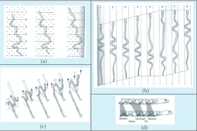
(c) (d)
(a) Lateral undulation: each point of the body passes successively by the head location via lateral bending of muscles alternate from one side to the other from the head to the tail.
(b) Concertina: one part of the body folds and creates a contact with the substratum while the other part is pushed or pulled from that contact.
(c) Sidewinding: some parts of the body are in contact while other are lifted producing a periodic static contact between the snake and the ground.
(d) Rectilinear: waves of contraction pass along the belly from one end to the other.
Figure 2.4 – How snakes move
in three classes depending if they have an endoskeleton, an exoskeleton or no skeleton at all. In the first case we meet all the vertebrates such as snakes, fishes, mammals, etc., while in the second major set (i.e. exoskeleton), we find the branch of arthropods which contains the class of insects or that of arachnids. Finally, other animals have no skeleton and recover the rigidity required by the contact efficiency by contracting isovolume tis-sues. Among these animals, named hydrostats, we find the worms or the octopus which is probably the most achieved living creature based on this principle. Another major classi-fication of morphologies relevant to robotics is their body’s topology, each animal’s body being possibly symbolized by a topological chain as those handled by multibody systems mechanics. In this case, simple open chain systems like the elongated body animals with no lateral appendices, are in fact very interesting for the roboticists since for a same sim-ple morphology, they show a wide set of possibilities ranging from swimming like eels, to burrowing like worms, creeping like snakes and so on. One of the reasons of the success of this morphology in the animal kingdom, is probably due to the fact that these animals have a high number of internal degrees of freedom (some big snakes have more than 500
2.2 Bioinspired Locomotion Robots 9 vertebrae) which make them what the roboticist names a hyper-redundant system. In this case, the degree of redundancy is the difference between the number of joint degrees of freedom of the skeleton with the six dimensions of their net displacements.
Beyond these bio-physics considerations, roboticists also get inspiration from the outstand-ing capabilities of animal locomotion to adapt to different environments. For example a same specie of snake has the ability to creep through undulation, sidewinding, rectilin-ear or concertina motion. In Fig. 2.4, these locomotion modes are shown and defined briefly[1]. All this is possible with the same morphology while shifting from one set of internal deformations to another which responds well to the environmental changes. More generally, the animal’s body is in fact capable of adapting to unstructured environments and their nervous control system has the ability to switch quickly and smoothly from one locomotion pattern to another according to the physical changes in the surrounding.
2.2
Bioinspired Locomotion Robots
For all the above mentioned reasons, a great deal of interest has been shown over the last few decades toward the design of locomotion robots inspired by animals. In the beginning, locomotion robots were designed on the basis of prior knowledge of the conventional industrial manipulators, i.e. as discrete multibody systems. Moreover, with the passage of time and the increase of targeted robots performances and understanding of animal locomotion, the designing aspects of the artificial locomotion systems were getting more and more inspiration from the nature. In this regard, the robot designs were shifted from the conventional discrete mechanisms toward novel hyper-redundant continuous structures with a dramatic increase in internal degrees of freedom as well as the number of bodies. Such hyper-redundant systems get inspiration mostly from elongated body animals such as snakes, eel-fish, etc. Here we present some successful prototypes of such highly articulated multibody systems. In underwater robotics when targeting manoeuvrability with high efficiency in open waters, the most achieved animals for bio-inspiration are probably the tuna fish whose cruising speed can reach 50km/h, while the red tuna can accelerate up to 75km/h and turns on it self in a fraction of second. Thus, seeking new solutions for drag reduction in naval hydrodynamics, Triantafyllou and co-workers of MIT were among the pioneers to investigate bio-inspired paradigm in this context. Under the RoboTuna project that was started at MIT in 1993, the fish-like robot called as ”Charlie-I” (Fig. 2.5(a)) inspired from the locomotion capabilities of the biological fish ”tuna” was designed and built in 1995. The major structural component of the robot fish is a segmented backbone made up from eight discrete rigid vertebra connected with ball bearing joints. These eight vertebra are driven through an elaborate system of pulleys and cable tendons by six servo motors mounted outside the robot body. These tendon drives are the mechanical analog of the biological fish’s muscles. As in the biological fish ”tuna”, the principal of propulsion
10 Chapter 2. Bio-inspired Locomotion Modeling: An Overview
(a) (b)
Figure 2.5 – The swimming robots of RoboTuna by MIT: (a) The ”Charlie-I”; (b) The ”RoboTuna-II”
was based upon the change in the internal orientation of the vertebra to each other that produced oscillation over the rare part of the body of robot. The main objective of this project being to study efficient systems of propulsion for the autonomous underwater vehicles with reduced drag and enhanced propulsion, the robot is towed and the resultant of hydrodynamic forces is measured for given cruising speeds and oscillations. The last robot of the RoboTuna project is the advanced version of the robotic fish Charlie-I, called as ”Robotuna-II” with several significant modifications as shown in Fig. 2.5(b). After RoboTuna, another robotic fish was designed at MIT called as ”RoboPike”. The aim of this new project is to reproduce the high accelerations of the pike (Esox lucius) which can reach 15g (g=9,81 ms−2) when catching a prey. Contrary to the RobotTuna, this robot
has its actuation mechanism inside its body. After these works, many swimming robots were then developed. Inspired from elongated anguilliform fishes such as eel and lamprey, some of them were using the undulation of the high number of internal degrees of freedom over the whole body instead of making use of oscillations of the rear part of their body like RoboTuna to propel in water. Examples of such robots are the eel-like robot of the French project RAAMO [2] or the amphibious snake-like robots called as Amphibot [35] and ACM-R5 [119], etc.
2.2.1
Bio-Inspired Snake-like Robots
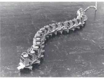
As an emblematic example of the discrete mobile multibody mechanism, the snake-like robot ACM-III [52] is a pioneering prototype and a first milestone in bio-inspired ter-restrial locomotion (Fig. 2.6). In 1972, this first bio-inspired serpentine robot called as ”Active Cord Mechanism” was made by Shigeo Hirose [52]. This robot was a two meter wheeled multibody system with twenty-one segments serially connected through (twenty) actuated single degree of freedom revolute joints. The purpose was to design and build a snake-like robot that is capable of producing an artificial serpentine movement same
2.2 Bioinspired Locomotion Robots 11
Figure 2.6 – The pioneering snake-like robot ACM-III with passive castor wheels
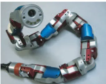
as that of actual snakes. This was the first successful attempt to mimic the serpentine movement, i.e. the forward movement produced with the help of internal actuated degrees of freedom. The passive castor wheels were used to form contact with the flat surfaces. These passive wheels ensure the frictional anisotropy of the ground friction forces, i.e. that the friction coefficient characterizing the ground friction forces in the normal (lateral) di-rection of each segment is larger than the friction coefficient characterizing the ground friction forces in the tangential (axial) direction of the segment. In natural snakes, the frictional anisotropy is provided by the ventral scales present on the snake belly [44, 55]. Taking advantage of the fact that, the propulsion mechanism of snakes is almost the same in both water and on ground, an amphibious version of the ”Active Cord Mechanism” series, called the ACM-R5 was presented in 2005 [119]. The snake-like robot ACM-R5, shown in Fig. 2.7(a), has the ability to move on the ground through ”crawling” as well as in the water through ”anguilliform” swimming. This water proof robot consists of nine segments serially connected through eight universal joints (i.e. through two degrees of freedom revolute joints between the consecutive segments). The universal joint allows the pitch and yaw degrees of freedom between segments as shown on Fig. 2.7(b). This robot has paddles with passive wheels (Fig.2.7(c)) that provide the necessary anisotropic ground friction properties required by lateral undulation i.e. allowing motion in the tan-gential direction, while preventing it in the normal direction.
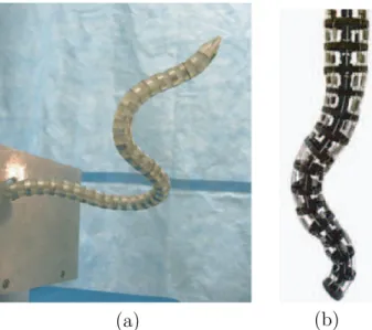
Developed by NTNU university of Norway with the research organization SINTEF, the wheeled robot ”Wheeko” is an experimental platform for studying wheeled snake-like robot locomotion across flat surfaces. As shown in Fig. 2.8(a) Wheeko consists of ten identical modules serially connected through universal joints. Each module of Wheeko is enclosed by a plastic ring mounted with twelve plastic passive wheels. The purpose of this prototype was to carry out motion control experiments in order to investigate the straight line path following controller.
loco-12 Chapter 2. Bio-inspired Locomotion Modeling: An Overview
(a) (b) (c)
Figure 2.7 – ACM-R5 snake-like robot with passive wheels
(a) (b)
Figure 2.8 – Snake-like robots designed by NTNU: (a) Wheeko with passive wheels; (b) Kulko with tactile sensors
motion through undulation was investigated and controlled both on ground and in water. From these successful developments, the researchers pushed the goal one step further to design the snake-like robots for performing tasks in highly unstructured environments in which case the above wheeled robots will definitely face difficulties to perform locomotion tasks, since they are good on flat surfaces. Thus, the wheel-less snake-like robots were designed for this purpose.
Kulko is a snake-like robot equipped with tactile sensors (Fig. 2.8(b)). The purpose of this model is to experimentally investigate the snake robot locomotion and control in environments with obstacles where this robot makes use of the obstacles as push points, like real snakes, to propel forward [70]. A set of force sensing resistors (FSRs), used as the tactile sensors, are placed on the modules to measure the environmental contact forces due to contact with obstacles.
2.2 Bioinspired Locomotion Robots 13
Figure 2.9 – Uncle Sam: snake-like robot at CMU
Among the most advanced results on snake-like robots, several modular robots were de-signed and built by researchers of the Biorobotics Laboratory at Carnegie Mellon Uni-versity (CMU) under the direction of Howie Choset [118, 50, 109]. One of such robots, called as ”Uncle Sam” is shown in Fig. 2.9. These wheel-less snake robots go beyond the capabilities of above mentioned conventional wheeled robots being limited to crawling and swimming. The modules are inter-connected in series via a single degree of freedom rotational joint in such a way that each module’s axis of rotation is rotated ninety degrees (π/2 rad) from the previous module in order to produce motions in all three dimensions [118]. Thus, capable of bending in the two lateral directions, these highly articulated snake-like robots can perform more difficult tasks such as stair climbing, gap crossing, channel climbing and many more. In short, one of the key problems posed by this kind of systems is to develop novel gaits capable of producing net displacement on difficult terrain [50].
With the success of snake-like robots in unstructured environments, an interest was developed in the research that involves interaction of animals with complex world such as granular media. Inspired from the locomotion of the sandfish in complex granular media, the sandfish robot (Fig. 2.10(a)) has recently been designed by the Complex Rheology And Biomechanics (CRAB) Laboratory in the School of Physics at the Georgia Institute of Technology. The basic mechanical design of this robot get inspiration from the existing snake-like robots to perform undulatory locomotion in sand. This robot has seven identi-cal modules serially connected through single degree of freedom joints. The purpose is to investigate the locomotion on the surface as well as inside a granular media [74]. As re-gards climbing robots, the Van der Valls adherence forces of high magnitude produced by the setae present on the toes of gecko lizard was the inspiration for the design of the ver-tical locomotion robot called as ”Stickybot” as shown in Fig. 2.10(b). This robot has four sticky legs with a rubber-like material with tiny polymer hairs made from a micro-scale
14 Chapter 2. Bio-inspired Locomotion Modeling: An Overview
(a) (b)
Figure 2.10 – (a) Sandfish robot; (b) Stickybot-III
mold, that allows the robot to climb smooth surfaces such as glass and metal.
Recent advances have shown the power of the bio-inspired approach in the field of control command. In fact, starting from works in neurobiology [45] on one of the most prim-itive fish, the anguilliform fish Lampetra fluviatilis, Auke Ijspeert and co-workers have implemented in [56] a distributed control on a real robotic artifact, mimicking the central pattern generators of the animal with a string of coupled nonlinear oscillators. Remark-ably, the approach inherits from the virtues of its natural model. In particular, when applied to an amphibious robot inspired from the salamander, it allows to shift smoothly from walking to swimming and vice versa.
Considering robots with more and more internal joints, the elephant trunk-like manip-ulator developed by Hannan and Walker [47] is an example of highly articulated elon-gated system (see Fig. 2.11(b)). Another example of a hyper-redundant manipulator is the highly articulated robotic probe called as ”CardioArm” developed by the Biorobotics Laboratory at Carnegie Melon University [90]. The first prototype of this robotic probe has already been developed and tested (see Fig. 2.11(a)). The purpose of this robot is to perform the minimally invasive cardiac surgery.
In all the above designs, the rigidity required by the propulsion is ensured by the presence of rigid bodies in their structures. However, inspired from hydrostats capable of continu-ous deformations along their body, researchers are nowadays designing soft body robots with no rigid bodies in their structure. They are inspired from tentacles, octopus arm, elephant trunk, inchworm, earthworm, etc. A soft robotic arm inspired from octopus is being developed by Cecilia Laschi’s crew under the European project ”OCTOPUS” [3]. This soft arm robot, with no rigid bodies in its structure, is composed of silicone and is driven by cables and shape memory alloy technologies [31]. As a fundamental unit of the octopus-like soft robotic arm, an ”artificial muscular-hydrostat” unit, as shown in Fig.
2.2 Bioinspired Locomotion Robots 15
(a) (b)
Figure 2.11 – Robotic arms: (a) CardioArm; (b) Elephant trunk-like manipulator
Figure 2.12 – Octopus Arm robot bio-inspired from octopus
2.12 has been developed to mimic the natural movements of a living octopus. The basic application of this waterproof soft robot is to perform underwater tasks such as movement and manipulation. The arm is used in water and it is able to elongate, shorten, and pull, as well as to bend in all the directions. As another example, a soft robot inspired from the caterpillar (a fluid-filled hydrostat) as shown in Fig.2.13is currently designed by the Tufts Neuromechanics and Biomimetic Devices Laboratory. The goal of these researches is to develop ”Biomimetic Technologies for Soft Bodied Robots”, i.e. to carry out investigations into innovative biologically-based technologies that use soft materials and to incorporate them into a new generation of highly flexible robot.
In short, all these researches indicate a high level of interest in the design, modeling, control, gait generation, etc., of highly articulated robots as well as soft robots that perform difficult tasks in highly unstructured and complex world.
16 Chapter 2. Bio-inspired Locomotion Modeling: An Overview
Figure 2.13 – Soft robot inspired from caterpillar
2.3
Modeling of Bio-inspired Locomotion Systems:
The Lagrangian Picture
2.3.1
Definition of a Mobile Multibody System
In the following we adopt the model of multibody systems to derive a general unified framework devoted to the modeling of locomotion - in particular bio-inspired - in robotics. A multibody system is a set of bodies interconnected through internal joints, and with the rest of the world through external joints or contacts. In all the thesis, we will consider the constitutive bodies as well as the joints as being rigid. This assumption is in fact justified by many of the technological artifacts as those introduced before and can be partially released as we will see in chapter 6 when we will consider the case of soft robots. Based on this basic model, we will first consider the case of discrete multibody systems consisted of a finite set of countable bodies, and in chapter 5we will see how it is possible to extend this model to the case of continuous robots. The usual model of rigid multibody systems is in fact very well developed in the context of manipulation, but much less when dealing with locomotion. In fact, contrary to classical multibody systems any body included in a locomotion system generally endure not only relative motion with respect to the other bodies, but also rigid overall motions due to the net displacements of the structure in the ambient space. Furthermore, these net motions are in general not imposed through explicit time laws, as on a manipulator mounted on a wheeled platform (or mobile manipulator for instance), but are produced at each time by the contact forces applied onto the whole system, i.e. by what we will name the locomotion dynamics of the system. By extension of the current terminology, in all the thesis we will name such a system a Mobile Multibody System or MMS and will distinguish it from classical Multibody System or MS. In spite of this semantic distinction, a MS is a particular case of MMS with rigid overall motions fixed through time laws, and in fact the methodological framework that we will develop about MMS will also be applicable to any MS. Finally referring to the usual designs of robotics, the ”mobile multibody systems” will include a lot of robotic systems ranging
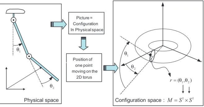
2.3 Modeling of Bio-inspired Locomotion Systems: The Lagrangian Picture 17 1 1 M =S ×S Configuration space : 1 θ 2 θ Physical space Picture = Configuration In Physical space Position of one point moving on the 2D torus 1 2 ( , ) r= θ θ 1 θ 2 θ
Figure 2.14 – Configuration space of a double pendulum: example maniflod
from a fully constrained system (such as a wheeled platform) to free floating system (such as space shuttles, satellites, etc.) via the conventional industrial manipulators, the under-constrained nonholonomic systems (e.g. the snakeboard, the trikke), etc. Before introducing our own contributions to the modeling of these systems (purpose of chapters 3, 4, 5 and 6), in the rest of this chapter we focus onto the most general existing theory today available in this context: the Lagrangian theory.
2.3.2
Configuration Space of a Mobile Multibody System
By ”Lagrangian” we here mean a theory which seeks to entirely derive the dynamics of a mechanical system from the knowledge of a unique function of its state, named Lagrangian of the system. Mathematically, such a theory enjoys a nice geometric basis which takes its roots in the theory of Riemannian geometry on manifolds. In mechanics, the key definition of this model is the concept of configuration manifold, or more simply of configuration space. Intuitively, the configuration space is the set of points whose coordinates are the parameters of the system. Thus, such a space is naturally endowed with a system of local coordinates or charts which gives the structure of a manifold to it. To any point of this abstract space, noted C, corresponds one and only one configuration of the whole system in the physical space R3. For a usual MS, as a manipulator with
n revolute joints parameterized by the vector of joint angles r = (r1, r2, ...rn)T, each ri
being related to a circle S1, the configuration space is a hyper torus of dimension n defined
by C = S1 × S1 × ...S1 = (S1)n (see Fig.2.14). Then, to a point of C corresponds one
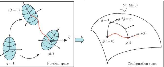
18 Chapter 2. Bio-inspired Locomotion Modeling: An Overview g(t = 0) g(t = 0) g = 1 g = 1 g(t) g(t) η Physical space G =SE(3) g−1˙g = η ˙g(t) Configuration space
Figure 2.15 – Configuration space of a rigid body
of the system requires not only to manage its shapes with the previous space that we name in this context ”shape space” and denote as S, but also its absolute position and orientation in the ambient space. Hence, we will say that a MMS has internal degrees of freedom defining its shape, and external degrees of freedom related to an external frame fixed to space. In the Lagrangian picture of geometric mechanics, the external degrees of freedom are parameterized by the transformations g applying a frame fixed to ambient space on a frame moving with the MMS. This mobile frame is called ”reference frame” and is generally attached to an arbitrarily distinguished body, named reference body, of the whole MMS. Of course the choice of this reference frame is not unique. In particular, among all the possibilities, we can define such a frame as a basis of three independent vectors attached to one of the body (which is the reference body) but originating in a non material point as for instance the gravity center of the whole MMS. In this case, the reference frame floats in space and is called ”floating frame”.
Geometrically, the transformations g, called ”net transformations”, are the elements of a Lie group G, i.e. a manifold endowed with an internal composition law satisfying the algebraic structure of a group1. There are several possibilities of such a group according to the case under consideration. For example, when the reference frame endures one dimensional translations, G = R. In case of translations in a plane, G = R2. In case of
motions in plane, G is named the group of Euclidean displacements in R2 and denoted
G =SE(2). For translations in three dimensional space, G = R3 and for rotations in three
dimensional space, G is the special orthogonal group G =SO(3). All these, and others, are included into the most general group G=SE(3) which defines the configuration space of a 3D rigid body and whose transformation elements g, can be represented by the 4 × 4
2.3 Modeling of Bio-inspired Locomotion Systems: The Lagrangian Picture 19
G
S (g, r)
r
Figure 2.16 – Configuration space as the principal fiber bundle
homogeneous matrices:
g = R p
0 1 !
,
where R and P respectively denote the rotation and the translation parts of the trans-formation. On its group of configurations, a motion of the rigid body defines a time parameterized curve and any of its tangent vector ˙g is named a velocity of transformation (see Fig. 2.15). Now the composition of two transformation in R3 corresponds on the
group to a translation of one by the other. Such a translation defining a map from points to points on G, we can take its tangent to translate ˙g in any point of G. In particular its translation on the left by g−1 moves the base point of ˙g from g to the unit element 1 and
defines the twist of the body in its mobile frame or ”material twist” η, which we detail as:
g−1˙g = Ω V
0 0
! = η,
where Ω and V respectively denote the angular and the linear velocities of the body in its mobile frame2. The set of the twists spans the tangent space to G at g = 1 noted T
1G.
Once endowed with the commutator such that for any η1, η2 ∈ T1G, [η1, η2] = η1η2− η2η1,
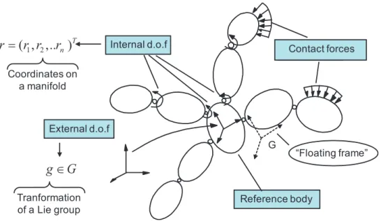
this space also defines the Lie algebra g of the group G, denoted se(3) in the case of SE(3). In the case of a MMS as shown in Fig. 2.17, to each configuration of the system corresponds a pair (g, r), i.e. a point of the configuration space (see Fig. 2.16):
C = G × S. (2.1)
2In this chapter, we do not distinguish a skew symmetric angular velocity matrix from its 3 × 1 vector,
20 Chapter 2. Bio-inspired Locomotion Modeling: An Overview
:
r
Internal d.o.f External d.o.f Reference body contact 1 2( , ,.. )
n Tr
=
r r
r
g
∈
G
“Floating frame” G Coordinates on a manifold Tranformation of a Lie group Contact forcesFigure 2.17 – Configuration space of a locomotion system: the principal fiber bundle
Such a space is indeed well known from differential geometry under the name of ”principal fiber bundle”. In differential geometry, a bundle is a manifold defined (at least locally) as the product of a manifold, named ”base manifold” with another space, named ”fiber” which is endowed with an algebraic structure. For example, if the fiber is a vector space, then the fiber bundle is a ”vector bundle” (more generally a ”tensor bundle”). If, as it is the case here, the fiber is a Lie group, then the fiber bundle is called a ”principal fiber bundle”. Finally, there exists a very rich corpus of results in geometric physics related to the structure of fiber bundle where it plays a crucial important role, for instance in gauge theory or general relativity. Hence, one of the strengths of the Lagrangian approach, whose we are going to remind a few key results, consists in having exploited this richness to use it to the benefit of a locomotion theory in robotics. In particular, in all the model of physics, a geometrical object is intimately associated to the concept of fiber bundle and even plays a more crucial role for the physicist; this is the concept of a ”connection”. However, before to introduce this concept and its use in locomotion, we are going to state the general problem that we will deal in the sequel of this thesis.
2.3.3
General Problem Addressed in this Thesis
The general problem of locomotion can be envisaged in multiple ways. In this thesis, we will solve the following problem. Knowing the time evolution on the internal joints r, we seek to compute:
1. The external net motions, which corresponds to solve the forward external dynamics called ”forward locomotion dynamics” (see Block2, Fig.2.18).
2.3 Modeling of Bio-inspired Locomotion Systems: The Lagrangian Picture 21 Block1: Torque Dynamics (motors) Block2: Locomotion Model (reference body)
Inputs: internal motions
Output: internal torques Output: net motions
Figure 2.18 – Flow chart of the recursive locomotion dynamics algorithm
more simply the ”inverse torque dynamics” (see Block1, Fig. 2.18).
This computation will be achieved by an algorithm whose general structure is illustrated in Fig. 2.18. Before to pursue our developments, let us do a few remarks.
First remark: The first dynamics are named ”locomotion dynamics” since by relating the internal to the external degrees of freedom (d.o.f), they involve the model of the contact forces which is at the base of the locomotion. On the other hand, the second dynamics are those usually met on standard MS as in the case of manipulators where they find their instantiation in the well known computed torque algorithms.
Second remark: A natural question arises from this statement: Why we opt for the choice of internal motions as inputs, why not to take torques as input? There are two main reasons. Firstly, it is an easy task to specify the motion of a locomotion robot in terms of its internal motion, while on the other hand it is not easy at all to infer its net motions from the torques exerted by its actuators on its internal joints. Secondly, and in relation to the first argument, this problem (and its solution) can be coupled to bio-logical experiments based upon locomotion films of the animals (see Fig. 2.19). In fact, once internal motions are extracted from such films, they can be imposed as inputs of the algorithm which feeds back the corresponding (modeled) external motions. Then, these external motions can be compared to the real ones extracted from the same films, and the matching of the measured and computed external motions, is a precious tool for the study of the model of the contact. In parallel, the inverse torque dynamics allows one to qualify the feasibility of the imposed internal motions with respect to the resources of actuators.
Third remark: Another relevant problem related to locomotion is the inverse of the above locomotion model, i.e. to find the internal shape motions in order to ensure given
22 Chapter 2. Bio-inspired Locomotion Modeling: An Overview
(Internal) shape motions
(External) net motions
Locomotion Model
Figure 2.19 – Problem of locomotion
external net motions. This is a control problem (for instance solved by optimal control theory). This problem will be not dealt in this work. However, let us remark that instead of inverting the locomotion model, one can seek to minimize the error between actual and desired values of external motions with respect to the unknown shape motions. This alternative way to solve the inverse problem (as an optimization problem) indeed uses the forward locomotion model that we study in this thesis. Finally, the algorithmic solution to the problem stated above is a useful tool for the design of gaits and transient maneuvers. On the other hand, solving the forward internal dynamics (i.e. torques as input, internal and external motions as output) has its own interests when seeking to model passive internal deformations as those exploited by animals through compliant locomotion organs allowing them to reduce their energetic consumption.
2.3.4
Forward Locomotion Dynamics: The Kinematic Case
Now based upon these concepts, motions on the manifold S are described by the internal shape motions while motions along Lie group G are the net motions of the reference body. Therefore, in order to solve the forward locomotion dynamics (see Fig. 2.19), we need to develop a relation between these two types of motions on the principal fiber bundle. In general to develop such relation, a dynamic model is required, i.e. the contact dynamics between the system and the surrounding medium has to be solved that we will discuss later in this chapter. However, there is a particular elegant case where locomotion is entirely defined by kinematics. This is when the model of the contact is encoded into what we name a connection on the principal fiber bundle of configurations [37]. In locomotion theory, such a connection exists when:
• there is a linear relation between small displacements on S and small displacements on G,
• this relation is such that (left) infinitesimal displacements in G are independent of g (left invariance).
This context is illustrated in Fig. 2.20. Replacing displacements by velocities, note that such a connection is free from dynamics and hence relates the net motions and the
(in-2.3 Modeling of Bio-inspired Locomotion Systems: The Lagrangian Picture 23 ˙ g g 1 η r r˙ G Horizontal space S
Figure 2.20 – Connection between motions ( ˙r) on S and motions (η) on G (from [32])
− →v (x) − →v (x + dx) M x x + dx TxM Tx+dxM r r + dr S G G g(r) g(r + dr)
Figure 2.21 – Fiber bundle: (a) principal fiber bundle G × S; (b) Tangent bundle T M of a manifold M
ternal) shape motions through simple kinematics as follows:
η + A(r) ˙r = 0. (2.2)
On the principal fiber bundle this relation operates in any point (g, r) through Adg(η +
A(r) ˙r) = 0 which defines the space of admissible velocities of the system, or in the language of differential geometry, a particular distribution on C named ”horizontal space” as illustrated on Fig.2.20. In the literature on geometric mechanics, A(r) is known as the local connection 1-form or more simply the local form of the connection. It is a function of the shape variables r only in virtue of the second condition mentioned above. In a more general way, a connection associates univocally a fiber element above a point over the base manifold to an element of the fiber above another infinitesimally close to the first one. This pairing is illustrated in Fig. 2.21(a) for a principal fiber bundle and for the tangent bundle of a manifold M in Fig. 2.21(b). In fact, this last context is very well known from Riemannian geometry where to any metric is naturally associated a connection named Levi-Civita connection and noted ω consisting in parallel transporting any tangent vector on the manifold along the geodesics of the metric [21]. In order to illustrate such a Riemannian connection, let us consider the case of the two dimensional sphere S2 endowed with the Euclidian metric induced from R3. Along any piece of great
24 Chapter 2. Bio-inspired Locomotion Modeling: An Overview
θ
S G g r S2Figure 2.22 – (a) Gauss-Bonnet theorem illustrated on S2; (b) A cyclic change of shape produces a net displacement in G
circle (which are the geodesics of S2), a vector tangent to the sphere can be parallel
transported from one point to another. Finally, by considering any curve on S2 as an
infinite set of infinitesimally short pieces of geodesics, parallel transport can be defined along any curve on S2. In particular, considering the particular case of closed curves
starting and finishing in a same point of S. When any vector is parallel transport along such a closed path, the vector after the whole transport appears as shifted of a given angle θ with respect to its antecedent. Furthermore, in virtue of the well known Gauss-Bonnet theorem this shift is in fact proportional to the area of the surface enclosed by the path and the curvature of the sphere (Fig. 2.22(a)). In other terms, this shift is a manifestation of the curvature of the manifold, and we have more generally:
θ = Z P ath ω = Z Enclosed area dω, (2.3)
which is nothing but a particular case of the Stokes theorem where dω is named the curvature 2-form of the Riemannian manifold. Remarkably, this context can be recovered in the case of the principal fiber bundle of a MMS when the fiber group is commutative (Fig. 2.22(b)). In this case, we can associate to (2.2) a curvature 2-form dA relating the infinitesimally small closed paths of a given gait on the shape space to the corresponding net displacements it produces in the fiber. As a results, this geometric picture is a precious tool of gait generation in robotics [8, 51]. Now, we are going to remind the two cases in robotics where forward locomotion dynamics can be modeled through kinematics using a connection.
2.3 Modeling of Bio-inspired Locomotion Systems: The Lagrangian Picture 25 G G
0
t =
1 rɺ 2 rɺ 3 rɺ Ω Falling cat Satellite with rotorsFloating frame
g ∈SO(3)
g∈SO(3)
Figure 2.23 – Mechanical connection: falling cat and satellite with rotors
Case1: Mechanical Connection
Let us take the example of a free-falling cat or a satellite reorientation system3 as shown in Fig. 2.23. It is well known that a cat, initially maintained in a steady position with its four legs up and then dropped, reorients its head by twisting its body through a complex shape motion. Finally at the end of its fall, the cat touch down with the shape it had at the initial time but with the four legs on the ground. By doing so, the falling cat solves a problem of locomotion without any contact, since air has no influence at all on its motion. In fact, as an orbiting satellite equipped with inertia wheels, the cat use transfers of inertia momentum between its internal and external d.o.f in order to reorient itself. Referring to our geometric point of view, the configuration space of these systems (the cat and the satellite) is a principal fiber bundle G × S with S the shape space of the cat skeleton in one case and the three dimensional torus in the case of the full actuated satellite4, and G =SO(3) in both cases. More precisely, we take the floating frame as the reference frame centered onto the gravity center of the system whose orientation with respect to a frame fixed to space is R ∈ SO(3). Then, according to the law of conservation of angular momentum, since no external forces are applied onto the system, its total angular momentum remains null all along the motion, i.e. σ = 0. Therefore, in this case the
3This system is treated in detail as an illustrative example in chapter4.
26 Chapter 2. Bio-inspired Locomotion Modeling: An Overview locomotion is ruled by the following relation:
σ = σfloating frame+ σshape = 0, (2.4)
where, σfloating frame is the angular momentum due the floating frame motions (i.e. the net
motions of the reference body), while σshape is the angular momentum due to the internal
shape motions. Thus, further analysis gives the angular momentum as follows: RTσ = I
o(r)Ωo+ Ir(r) ˙r = 0, (2.5)
where, Io is the angular inertia matrix of the system when it is rigidified in its current
shape r, or locked inertia matrix; and Iris the inertia coupling matrix between internal and
external accelerations. As the above relation is left invariant (Ioand Irare R-independent)
and linear, it defines the following connection:
A(r) = Io−1(r)Ir(r) = 0. (2.6)
In literature on geometric mechanics, such a connection is known as the ”mechanical connection” [84]. It encodes all the information about the kinetic exchanges between the internal and external degrees of freedom. In spite of appearances, note that referring to our introductive considerations about animal locomotion, the locomotion mechanism used by the cat is again a kind of action-reaction principle, but where the inertia (Coriolis and centrifugal) forces replace the external forces of the general context. Finally, before to close this example, let us remark that applying the same considerations to the translations of the floating frame gives in virtue of the mass center theorem:
A(r) = 0. (2.7)
since no external forces is applied to the system. Thus, in this second case, the internal shape motions cannot act onto the linear motions of the floating frame. In simple words there is no ”connection” between these motions.
Case2: Kinematic Connection
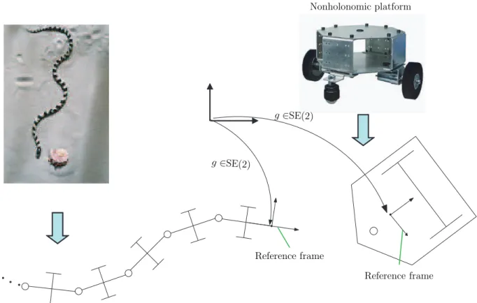
Now we consider the examples of an undulatory snake and a nonholonomic wheeled (uni-cycle) platform as shown in Fig. 2.24. The reference frame is attached to the head of the snake and to the platform. Since both systems evolves in the plane, the principle fiber bundle of their configurations is SE(2) × S where S stands for the space of the snake skeleton in one case, and for the two dimensional torus of the unicycle wheels, in the other. Once again, there exists a connection [60, 99, 89] between internal shape motions and external net motions of these two systems. This connection is deduced by assuming
2.3 Modeling of Bio-inspired Locomotion Systems: The Lagrangian Picture 27 Nonholonomic platform g ∈SE(2) g ∈SE(2) Reference frame Reference frame
Figure 2.24 – Kinematic connection: snake in lateral undulation and unicycle-platform
that the contacts between the ground and the scales in one case, and the wheels in the other are modeled by ideal non-sliding (NS) and rolling without slipping (RWS) condi-tions5. To derive the expression of this connection, it suffices to insert the motion of the reference frame in the NS and RWS conditions and to gather in both cases a set of 3 (=dim(SE(2))) independent nonholonomic constraints on the principal fiber bundle. In this way, we obtain the well known kinematic model of wheeled mobile platforms:
η + A(r) ˙r = 0. (2.8)
Where once again the A(r) matrix, being g independent, defines the local form of a connection known as the principal kinematic connection [8]. Note, that in case of snake-like robot, this connection is built up from the lateral non-sliding constraints (the wheels being passive), while the unicycle platform requires to use the rolling without slipping constraints of the two actuated wheels in addition. These nonholonomic constraints are discussed in detail in chapter 3 while dealing with wheeled systems.
5In the case of the snake, the strong frictional anisotropy of its skin along axial and lateral directions